EIA-364-28E 电子连接器振动测试方法-中英
EIA 364-27、28 机械冲击讲义

锯齿冲击脉冲终点峰值公差
速度的变化量:Vi= 0.5AD X10-3 (P 为加速度的峰值,D 为脉冲持续时间)的±10%以内。 最大峰值脉冲振幅±15%以内,峰值加速度±15%以内。
中文名称: 后峰锯齿冲击脉冲 英文名称: final peak sawtooth shock pulse 定义: 时间历程曲线为三角形的,即运动量 由零线性地增加到最大值然后在一瞬间降落 到零的理想冲击脉冲。
8、瞬断,及连接方法:
EIA-364-46:电子连接器的微秒间断试验程 序,连接器和插座。 1、监控设备电压电流 DC5V 100MA 电源调节响应时间应0.1微 秒或更好。 2、连接每个监控串联电路不超过50个连接 点,且初始电阻小于3 Ω.
❖EIA-364-87:电子连接器的纳秒事件检测, 连接器和插座。
1、测试的目的:
❖1、范围:描述一种电连接器机械冲击试验 的标准方法,以便评估电连接器及其组件 耐机械冲击的性能。
❖ 2、目的:进行本试验是为了确定连接器及 其组件当遭到诸如粗鲁搬运、运输或军用 时可能出现的冲击的适应性。
2、机械冲击的概念
定义:能激起系统瞬态扰动的力、位置、速 度和加速度的突然变化。
1.2 目的: 进行本试验是为了确定连接器及其组件在 寿命期间可能遭遇在主要频段或随机振动 频段范围内及其幅度上受振动的影响情况。
5、振动的概念
机械振动是物体在一定位置附近所作的周
期性往复的运动。
机械振动系统,就是指围绕其静平衡位置 作来回往复运动的机械系统,单摆就是一 种简单的机械振动系统。
振动测试的基本参数
测试方向: ±(X、Y、Z)
冲击波形: 半正弦 锯齿波
冲击次数: 每轴向的次数
机械 冲击
EIA-364-27B中文版
EIA STANDARD EIA-364-27B 第1 页共7 页电子工业协会标准TP-27B电连接器的机械冲击(规定脉冲)试验程序EIA-364-27B(依据EIA-364-27A修订)1996年4月17日颁布1 目的描述一种电连接器机械冲击试验的标准方法,以便评估电连接器及其组件耐机械冲击的性能。
2 概述进行本试验是为了确定连接器及其组件当遭到诸如粗鲁搬运、运输或军用时可能出现的冲击的适应性。
测试系统的频率响应亦以容差规定。
3 定义3.1 轴图1给出了轴的图示定义,如果使用不同于图1所示的轴,则在相关参考文件中应在试验装置进行要求或对轴进行定义。
3.1.1 X轴与样品纵向长度一致的方向3.1.2 Y轴与样品纵向相垂直的方向(横向)3.1.3 Z轴与测试装置的固定面(与试验桌的桌面接触的面)垂直的方向图1---安装轴向定义4 样品制备4.1 除非另有规定,样品应按规定连接。
4.2 样品应按规定安装为了将不平衡负载的影响减至最小,应尽量将样品在试验平台上的试验负载分布均匀。
5 试验方法5.1 试验设备5.1.1 冲击机所使用的冲击试验机就能产生规定的输入冲击脉冲,如图2或图3所示。
冲击试验机的振动形式可以是自由跌落式,弹性回跳式,非弹性式,压缩空气式或其它振动形式。
5.1.1.1 冲击试验机的校准可以使用一个实际的试验项目或一个模拟的负载来校准试验机。
然后用规定的波形来校准冲击机,两次边疆的冲击施加在校准负载上应产生如图2或图3所给出的误差包络线内的波形。
然后拆除校准负载而对实际的样品进行冲击。
除了用实际样品替代校准负载外,如果所有保留条件相同,就应认为这样的校准符合波形的要求。
5.1.2测量仪器传感器应用标准的传感器进行校准,应达到±2%的精度。
为了达到试验程序的误差要求,测量仪器应满足下列特性:5.1.2.1 频率响应整个测量系统的频率响应,包括传感器和读出装置,应符合图4中的规定。
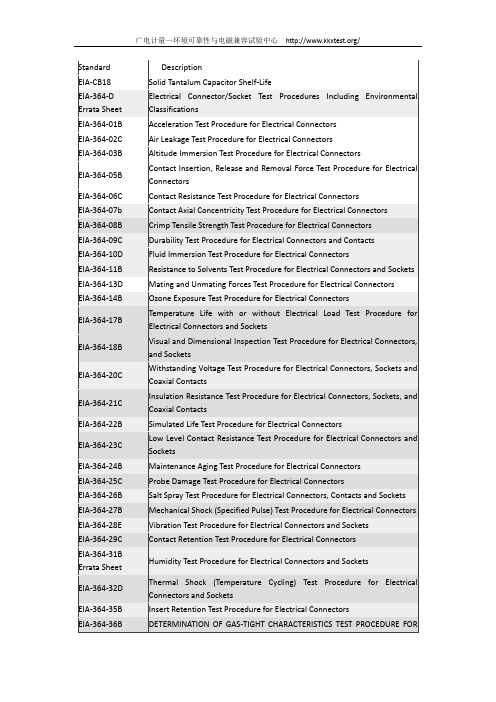
EIA-364(连接器产品常用测试规范之目录)

EIA-364(连接器产品常用测试规范之目录)Item Standard NO.Rev.Description1EIA-CB18Solid Tantalum Capacitor Shelf-Life固体的钽式电容器储存期限2EIA-364E ELECTRICAL CONNECTOR/SOCKET TEST PROCEDURES INCLUDING ENVIRONMENTAL CLASSIFICATIONS 电子连接器/插座(包括环境类)的测试程序3EIA-364-01B Acceleration Test Procedure for Electrical Connectors电子连接器的加速测试程序4EIA-364-02C Air Leakage Test Procedure for Electrical Connectors空气渗漏电子连接器的测试程序5EIA-364-03B Altitude Immersion Test Procedure for Electrical Connectors高度浸入电子连接器的测试程序6EIA-364-05B Contact Insertion, Release and Removal Force Test Procedure for Electrical Connectors电子连接器的端子插入、释放及取出测试程序7EIA-364-06C Contact Resistance Test Procedure for Electrical Connectors电子连接器的接触电阻测试程序8EIA-364-07B Contact Axial Concentricity Test Procedure for Electrical Connectors电子连接器的端子同心度测试程序9EIA-364-08B Crimp Tensile Strength Test Procedure for Electrical Connectors电子连接器的卷曲抗拉强度测试程序10EIA-364-09C Durability Test Procedure for ElectricalConnectors and Contacts端子连接器与端子的耐久性测试程序11EIA-364-10D Fluid Immersion Test Procedure for Electrical Connectors电子连接器的液体浸没测试程序12EIA-364-11B Resistance to Solvents Test Procedure for Electrical Connectors and Sockets电子连接器和插座的电阻测试程序13EIA-364-13D Mating and Unmating Forces T est Procedure for Electrical Connectors电子连接器的插入力和拔出力测试程序14EIA-364-14B Ozone Exposure Test Procedure for Electrical Connectors电子连接器的臭氧暴露测试程序15EIA-364-17B Temperature Life with or without Electrical Load Test Procedure for Electrical Connectors andSockets. 电子连接器和插座的温度寿命测试或没有电负载测试程序16EIA-364-18B Visual and Dimensional Inspection Test Procedure for Electrical Connectors and Sockets电子连接器和插座的外观与尺寸检验程序17EIA-364-20C Withstanding Voltage Test Procedure for Electrical Connectors, Sockets and Coaxial Contacts电子连接品、插座和同轴端子的耐电压测试程序18EIA-364-21C Insulation Resistance Test Procedure for Electrical Connectors, Sockets, and Coaxial Contacts电子连接品、插座和同轴端子的绝缘电阻测试程序19EIA-364-22B Simulated Life Test Procedure for Electrical Connectors电子连接器的模拟寿命测试程序20EIA-364-23C Low Level Contact Resistance T est Procedure for Electrical Connectors and Sockets电子连接器与插座的接触电阻测试程序21EIA-364-24B Maintenance Aging Test Procedure for Electrical Connectors电子连接器的维持能力测试程序22EIA-364-25C Probe Damage Test Procedure for Electrical Connectors电子连接器的探伤测试程序23EIA-364-26B Salt Spray Test Procedure for Electrical Connectors, Contacts and Sockets电子连接器、端子和插座的盐雾测试程序24EIA-364-27B Mechanical Shock (Specified Pulse) Test Procedure for Electrical Connectors电子连接器的机械震动(指定的脉搏)测试程序25EIA-364-28E Vibration Test Procedure for Electrical Connectors and Sockets电子连接器与插座的振动测试程序26EIA-364-29C Contact Retention Test Procedure for Electrical Connectors电子连接器的端子保持力测试程序27EIA-364-30A Capacitance Test Procedure for Electrical Connectors and Sockets电子连接器与插座的电容测试程序28EIA-364-31B Humidity Test Procedure for Electrical Connectors and Sockets电子连接器与插座的湿度测试程序29EIA-364-32D Thermal Shock (Temperature Cycling) Test Procedure for Electrical Connectors and Sockets电子连接器与插座的热冲击(温度周期变化)测试程序30EIA-364-35B Insert Retention Test Procedure for Electrical Connectors电子连接器的保持力测试程序31EIA-364-36B Determination of Gas-tight Characteristics test procedure for Electrical connectors and or contact systems. 电子连接器和(或)端子系统的气密特性测试程序32EIA-364-37B Contact Engagement and Separation Force Test Procedure for Electrical Connectors电子连接器端子结合力和分离力测试程序33EIA-364-38B Cable Pull-Out Test Procedure for Electrical Connectors电子连接器的电材拉拔力测试程序34EIA-364-39B Hydrostatic Test Procedure for Electrical Connectors, Contacts and Sockets电子连接器、接触和插座的液压静力测试程序35EIA-364-40B Crush Test Procedure for Electrical Connectors电子连接器v压坏测试程序36EIA-364-41C Cable Flexing Test Procedure for Electrical Connectors电报在电子连接的测试程序屈曲37EIA-364-42B Impact Test Procedure for Electrical Connectors电子连接器的机械冲压测试程序38EIA-364-45A Firewall Flame Test Procedure for Electrical Connectors电子连接器的阻燃火焰测试程序39EIA-364-46B MICROSECOND DISCONTINUITY TEST PROCEDURE FOR ELECTRICAL CONNECTORS,CONTACTS AND SOCKETS电子连接器、端子和插座的瞬断(微秒不间断)测试程序40EIA-364-48A Metallic Coating Thickness Measurement of Contacts Test Procedure for Electrical Connectors电子连接器端子喷涂层厚底测试程序41EIA-364-50A Dust (Fine Sand)Test Procedure for Electrical Connectors电子连接器的粉尘(细沙)测试程序42EIA-364-53B Nitric Acid Vapor Test, Gold Finish Test Procedure for Electrical Connectors and Sockets电子连接器与插座的硝酸蒸汽测试、黄金制品测试程序43EIA-364-54A Magnetic Permeability Test Procedure for Electrical Connectors, Contacts, and Sockets电子连接器、端子和插座的导电率测试程序44EIA-364-56C Resistance to Soldering Heat Test Procedure for Electrical Connectors and Sockets电子连接器和插座的焊接热电阻测试程序45EIA-364-59A LOW TEMPERATURE TEST PROCEDURE FOR ELECTRICAL CONNECTORS AND SOCKETS电子连接器和插座的低温测试程序46EIA-364-66A EMI Shielding Effectiveness Test Procedure for Electrical Connectors电子连接器的电磁干扰屏蔽效应测试程序47EIA-364-70B TEMPERATURE RISE VERSUS CURRENT TEST PROCEDURE FOR ELECTRICAL CONNECTORS AND SOCKETS 电子连接器与插座的温升与电流测试程序48EIA-364-71B Solder Wicking (Wave Solder Technique) Test Procedure for Electrical Connectors and Sockets电子连接器与插座的溢锡(波峰焊接技术)测试程序49EIA-364-75LIGHTNING STRIKE TEST PROCEDURE FOR ELECTRICAL CONNECTORS电子连接器的雷击测试程序50EIA-364-81A Combustion Characteristics Test Procedure for Electrical Connector Housings, Connector Assemblies and Sockets. 电子连接器塑料、组装成品与插座的燃烧特性测试程序51EIA-364-82A Corrosivity of Plastics Test Procedure for Electrical Connector and Socket Housings电子连接器与插座塑胶的塑胶腐蚀性测试程序52EIA-364-83Shell-to-Shell and Shell-to-Bulkhead Resistance Test Procedure for Electrical Connectors电子连接器的接地壳与接地壳及接地壳与主板之电阻测试程序53EIA-364-89A Space Application Test Procedure for Electrical Connectors and Sockets电子连接器与插座的空间应用测试程序54EIA-364-90Crosstalk Ratio Test Procedures for Electrical Connectors, Sockets, Cable Assemblies orInterconnect Systems电子连接器、插座、线束或互联系统的串扰率测试程序55EIA-364-91A Dust Test Procedure for Electrical Connector and Sockets电子连接器与插座的粉尘测试程序56EIA-364-95Full Mating and Mating Stability Test Procedures for Electrical Connectors电子连接器的完整互配与互配稳定测试程序57EIA-364-99Gage Location and Retention Test Procedure for Electrical Connectors电子连接器的计量位置与保留测试程序58EIA-364-100Marking Permanence Test Procedure for Electrical Connectors and Sockets电子连接器与插座的永久性标识测试程序59EIA-364-101Attenuation Test Procedure for Electrical Connectors, Sockets, Cable Assemblies or Interconnection Systems 电子连接器、插座、线束或互联系统的衰减测试程序60EIA-364-102Rise Time Degradation Test Procedure for Electrical Connectors, Sockets,Cable Assemblies orInterconnection Systems。
EIA-364-28F_(2011-01-14)_Vibration

EIASTANDARDTP-28FVIBRATION TEST PROCEDURE FOR ELECTRICAL CONNECTORS AND SOCKETSEIA-364-28FJANUARY 2011EIA StandardsElectronic Components AssociationANSI/EIA-364-28F-2011Approved: January 14, 2011E I A -364-28FNOTICEThis standard is based upon the major technical content of International Electrotechnical Commission standard 60512-2-1 2005-Febuary (was IEC 512-2, test 2a), contact resistance - millivolt level method. It conforms in all essential respects this IEC standard.EIA Engineering Standards and Publications are designed to serve the public interest through eliminating misunderstandings between manufacturers and purchasers, facilitating interchangeability and improvement of products, and assisting the purchaser in selecting and obtaining with minimum delay the proper product for his particular need. Existence of such Standards and Publications shall not in any respect preclude any member or nonmember of ECA from manufacturing or selling products not conforming to such Standards and Publications, nor shall the existence of such Standards and Publications preclude their voluntary use by those other than ECA members, whether the standard is to be used either domestically or internationally.Standards and Publications are adopted by ECA in accordance with the American National Standards Institute (ANSI) patent policy. By such action, ECA does not assume any liability to any patent owner, nor does it assume any obligation whatever to parties adopting the Standard or Publication.This major portion of this Standard is based upon the technical content of International Electrotechnical Commission standard IEC 60512-6-4, (was IEC 512-4, test 6d) Dynamic Stress, Vibration (Sinusoidal), 2002 and also IEC 60512-6-5, Dynamic Stress, Random Vibration, 1997. It differs from IEC Publication 60068-2-6 (was IEC 68-2-6, test Fc), Vibration (Sinusoidal), 2007; by specifying a single test with closely controlled conditions and methods for random vibration. These differences have been called to the attention of the U.S. Committee of Experts for IEC (or ISO) Technical Committee TC48 and resolution of these differences will be sought in future meetings of SC48. Test condition VII is based on International Electrotechnical Commission standard IEC 60068-2-34, (was IEC 68-2-34, Test Fd), Random Vibration Wide Band, 1993.This Standard does not purport to address all safety problems associated with its use or all applicable regulatory requirements. It is the responsibility of the user of this Standard to establish appropriate safety and health practices and to determine the applicability of regulatory limitations before its use.(From Standards Proposal No. SP-5212 formulated under the cognizance of the CE-2.0 National Connector Standards Committee).Published by©ELECTRONIC COMPONENTS ASSOCIATION 2011Engineering Department2500 Wilson Boulevard, Suite 310Arlington, VA 22201PRICE: Please call: IHSUSA and Canada (1-800-854-7179)All rights reservedPrinted in U.S.A.PLEASE!DON'T VIOLATETHELAW!This document is copyrighted by the ECA and may not be reproduced without permission.Organizations may obtain permission to reproduce a limited number of copies through entering into a license agreement. For information, contact:IHS15 Inverness Way EastEnglewood, CO 80112-5704 or callUSA and Canada (1-800-854-7179), International (303-397-7956)CONTENTSClause Page 1 Introduction (1)1.1 Scope (1)1.2 Object (1)1.3 Applicable documents (1)1.4 Definitions (1)2 Test resources (2)2.1 Equipment (2)3 Test specimen (3)4 Test procedure (4)4.1 Test conditions I, II, III and IV (4)4.2 Test conditions V, VI and VII (10)5 Details to be specified (16)6 Test documentation (17)Table1 Vibration conditions (4)2 Values for test condition V (13)3 Values for test condition VI (14)4 Values for test condition VII (15)Figure1 Mounting axis definitions (2)2 Vibration test curves - high frequency (displacement in mm) (6)3 Vibration test curves - high frequency (displacement in inches) (7)4 Test condition V, random vibration test curve envelope (13)5 Test condition VI, random vibration test curve envelope (14)6 Test condition VII, random vibration test curve envelope (15)(This page left blank)TEST PROCEDURE No. 28FVIBRATION TEST PROCEDUREFORELECTRICAL CONNECTORS AND SOCKETS(From EIA Standards Proposal No. 5212, formulated under the cognizance EIA CE-2.0 Committee on National Connector Standards, and previously published in EIA-364-28E.)1 Introduction1.1 ScopeThe standard test procedure details a method to assess the ability of electrical connector components to withstand specified severities of vibration.1.2 ObjectThe object of this test is to determine the effects of vibration within the predominant or random vibration frequency ranges and magnitudes that may be encountered during the life of the connector.1.3 Applicable documentsThe following documents form a part of this standard to the extent indicated herein. In the event of conflict between the requirements of this standard and the referenced documents, this standard takes precedence.1.3.1 EIA standardsEIA-364-46: Microsecond Discontinuity Test Procedure for Electrical Connectors, Contacts and SocketsEIA-364-87: Nanosecond Event Detection for Electrical Connectors, Contacts and Sockets1.4 Definitions1.4.1 AxisThe following mounting axis definitions shall be employed during the performance of this test. Figure 1 indicates a pictorial view of the axis definitions. The referencing document shall indicate the fixturing required or the axis definitions if different than as stated in figure 1. Axis definitions for symmetrical, square and “free” connectors shall be defined in the Detail Specification.1.4.1.1 X-axisAlong the longitudinal length of the test sample1.4.1.2 Y-axisThe axis perpendicular to the longitudinal length of the sample (transverse direction).1.4.1.3 Z-axisThe axis perpendicular to the fixture seating plane attached to the test table.Figure 1 - Mounting axis definitions1.4.2 The term gnThis term is the SI unit for the standard acceleration due to the earth’s gravity, which itself varies with altitude and geographic latitude. NOTE — In this standard the value of g n is 9.81 m/s 2.2. Test resources2.1 Equipment2.1.1 The monitoring transducer shall be calibrated against a standard transducer having an accuracy of ±2%. The vibration system consisting of the vibration machine, together with its auxiliary test equipment, shall be capable of generating either a sinusoidal or random excitation.2.1.2 Test equipment for random vibration shall produce random excitation that possesses a gaussian (normal) amplitude distribution, except that the acceleration magnitudes of the peak values may be limited to a minimum of three times the rms [three-sigma (3σ) limits].3 Test specimen3.1 A vibration test sample shall be a fully wired connector consisting of one of the following, as applicable;3.1.1 A connector plug and its mating connector receptacle.3.1.2 A printed circuit connector receptacle and its mating connector board(s).3.1.3 An integral, functional connector assembly.3.2 Each test sample shall be prepared with wire and other materials or processes, simulating application assembly of the sample. If normal connector mating is dependent upon forces external to the connector, then such forces and mounting arrangement shall be as closely duplicated as possible (example: printed circuit connectors). If mating is achieved with normal locking means, then only normal locking means shall be used.3.3 Method of mounting3.3.1 Test conditions I, II, III and IV (sinusoidal evaluation conditions)The specimen shall be attached to a fixture capable of transmitting the vibration conditions specified. The test fixture shall be designed so that resonant vibration inherent in the fixture within the frequency range specified for the test shall be minor. The magnitude of the applied vibration shall be monitored on the test fixture near the specimen mounting points. The test specimen shall be mounted rigidly to the test fixture as specified and shall simulate as closely as possible the normal mounting of the specimen. A minimum of 200 mm (approx 8 in) of wire or cable shall be unsupported on both ends of the connector. For specimens with attached brackets, one of the vibration-test directions shall be parallel to the mounting surface of the bracket. Vibration input shall be monitored on the mounting fixture in the proximity of the support points of the specimen.3.3.2 Test conditions V, VI and VII (random excitation conditions)The specimen shall be mounted as specified. The orientation of the specimen or direction of application of the applied vibration motion shall be specified in one or more directions. If the order of application of the different directions is critical, it also shall be specified. Any special test fixtures or jigs required to run the test shall be specified in sufficient detail to assure reproducibility of the input motion applied to the specimen. These details shall include the dimensions, the materials, temper, etc., as applicable.4 Test procedureTests and measurements before, during and after vibration shall be as specified in the referencing document.4.1 Test conditions I, II, III and IV4.1.1 Electrical load and discontinuity4.1.1.1 Unless otherwise specified in the referencing document, an electrical load of 100 milliamperes maximum with a detector capable of detecting a discontinuity of 1.0 microsecond or longer. Said monitoring shall be performed in accordance with EIA-.364-46.4.1.1.2 Unless otherwise specified in the referencing document, low nanosecond event detection shall be performed in accordance with EIA-364-87. A 100 milliamperes test current shall be applied to the areas being monitored. A detector capable of measuring an event resulting in a 10 ohm change lasting longer than 10 nanoseconds, unless otherwise specified in the referencing document.4.1.1.2.1 Low nanosecond event detection shall not be used as a substitute for the standard 1.0 microsecond requirement. This monitoring test was developed to detect different failure mechanisms than that described in 4.1.1.1. It is designed to detect large resistance fluctuations or voltage variations that may result in improper triggering of high speed digital circuits.4.1.2 Vibration conditionsVibration conditions shall be in accordance with table 1, as applicable.Table 1 - Vibration conditionsTest conditions Frequency range, Hz Peak levelg n m/s2I Low - 10 to 55II High - 10 to 500 10 98.1III High - 10 to 2,000 15 147.1IV High - 10 to 2,000 20 196.14.1.3 ResonanceA critical resonant frequency is that frequency at which any point on the specimen is observed to have a maximum amplitude more than twice that of the support points. When specified, resonant frequencies shall be determined either by monitoring parameters such as contact opening, or by use of resonance-detecting instrumentation.4.1.4 Test condition IThe specimens shall be subjected to a simple harmonic motion having an amplitude 1.52 mm (0.06 in) double amplitude (maximum total excursion), the frequency being varied uniformly between the approximate limits of 10 Hz and 55 Hz. The entire frequency range, from 10 Hz to 55 Hz and return to 10 Hz, shall be traversed in approximately 1 minute. Unless otherwise specified, this motion shall be applied for 2 hours in each of three mutually perpendicular directions (total of 6 hours). If applicable, this test shall be made under electrical load conditions.4.1.5 Test condition II [98.1 m/s2 (10 g n) peak]The specimens, while deenergized or operating under the load conditions specified, shall be subjected to the vibration amplitude, frequency range, and duration specified 4.1.5.1, 4.1.5.2 and 4.1.5.3, respectively; see figures 2 and 3.4.1.5.1 AmplitudeThe specimens shall be subjected to a simple harmonic motion having an amplitude of either 1.52 mm (0.06 in) double amplitude (maximum total excursion) or 98.1 m/s2(10 g n) peak, whichever is less. The tolerance on vibration amplitude shall be ±10%.4.1.5.2 FrequencyThe vibration frequency shall be varied logarithmically between the approximate limits of 10 Hz and 500 Hz (see 4.1.8) except that the procedure (see 4.1.4) of this standard may be applied during the 10 Hz to 55 Hz band of the vibration frequency range.4.1.5.3 Sweep time and durationThe entire frequency range of 10 Hz to 500 Hz and return to 10 Hz shall be traversed in 15 minutes. This cycle shall be performed 12 times in each of three mutually perpendicular directions (total of 36 times), so that the motion shall be applied for a total period of approximately 9 hours. Interruptions are permitted provided the requirements for rate of change and test duration are met. Completion of cycling within any separate band is permissible before going to the next band. When the procedure (see 4.1.4) is used for the 10 Hz to 55 Hz band, the duration of this portion shall be same as the duration for this band using logarithmic cycling (approximately 1-1/3 hours in each of three mutually perpendicular directions).4.1.6 Test condition III 147.1 m/s2 (15 g n) peak]The specimens, while deenergized or operating under the load conditions specified, shall be subjected to the vibration amplitude, frequency range, and duration specified in 4.1.6.1, 4.1.6.2 and 4.1.6.3, respectively; see figures 2 and 3.NOTE: g = 0.00201f 2 DA (f = frequency in hertz, DA = double amplitude in mm)Figure 2 - Vibration test curves - high frequency (displacement in mm)NOTE: g = 0.0512f 2 DA (f = frequency in hertz, DA = double amplitude in inches) Figure 3 - Vibration test curves - high frequency (displacement in inches)4.1.6.1 AmplitudeThe specimens shall be subjected to a simple harmonic motion having an amplitude of either 1.52 mm (0.06 in) double amplitude (maximum total excursion) or 147.1 m/s2(15 g n) peak, whichever is less. The tolerance on vibration amplitude shall be ±10%.4.1.6.2 Frequency rangeThe vibration frequency shall be varied logarithmically between the approximate limits of 10 Hz to 2,000 Hz (see 4.1.8) except that the procedure (see 4.1.4) of this standard may be applied during the 10 Hz to 55 Hz band of the vibration frequency range.4.1.6.3 Sweep time and durationThe entire frequency range of 10 Hz to 2,000 Hz and return to 10 Hz shall be traversed in 20 minutes. This cycle shall be performed 12 times in each of three mutually perpendicular directions (total of 36 times), so that the motion shall be applied for a total period of approximately 12 hours. Interruptions are permitted provided the requirements for rate of change and test duration are met. Completion of cycling within any separate band is permissible before going to the next band. When the procedure (see 4.1.4) of this standard is used for the 10 Hz to 55 Hz band, the duration of this portion shall be the same as the duration for this band using logarithmic cycling (approximately 1-1/3 hours in each of three mutually perpendicular directions).4.1.7 Test condition IV [196.1 m/s2 (20 g n) peak]The specimens, while deenergized or operating under the load conditions specified, shall be subjected to the vibration amplitude, frequency range, and duration specified in 4.1.7.1, 4.1.7.2 and 4.1.7.3, respectively; see figures 2 and 3.4.1.7.1 AmplitudeThe specimens shall be subjected to a simple harmonic motion having an amplitude of either 1.52 mm (0.06 in) double amplitude (maximum total excursion) or 196.1 m/s2(20 g n) peak, whichever is less. The tolerance on vibration amplitude shall be ±10%.4.1.7.2 Frequency rangeThe vibration frequency shall be varied logarithmically between the approximate limits of 10 Hz to 2,000 Hz (see 4.1.8).4.1.7.3 Sweep time and durationThe entire frequency range of 10 Hz to 2,000 Hz and return to 10 Hz shall be traversed in 20 minutes. This cycle shall be performed 12 times in each of three mutually perpendicular directions (total of 36 times), so that the motion shall be applied for a total period of approximately 12 hours. Interruptions are permitted provided the requirements for rate of change and test duration are met.Completion of cycling within any separate band is permissible before going to the next band. When the procedure (see 4.1.4.) of this standard is used for the 10 Hz to 55 Hz band, the duration of this portion shall be the same as the duration for this band using logarithmic cycling (approximately 1-1/3 hours in each of three mutually perpendicular directions).4.1.8 Alternative procedure for use of linear in place of logarithmic change of frequency Linear rate of change of frequency is permissible under the following conditions:4.1.8.1 The frequency range above 55 Hz shall be subdivided into no fewer than three bands. The ratio of the maximum frequency to the minimum frequency in each band shall be not less than two (2).4.1.8.2 The rate of change of frequency in Hz per minute shall be constant within any one band.4.1.8.3 The ratios of the rate of change of frequency of each band to the maximum frequency of that band shall be approximately equal.4.1.8.3.1 Example of alternative procedureAs an example of the computation of rates of change, assume that the frequency spectrum has been divided into three bands, 55 Hz to 125 Hz, 125 Hz to 500 Hz and 500 Hz to 2,000 Hz, in accordance with 4.1.8.1. For each band, let the constant, κ, represent the frequency change (in Hz/minute), divided by the maximum frequency (in Hz). Then the rates of change for the three bands will be 125κ, 500κ and 2,000κ, respectively. The times (in minutes) to traverse the three frequency bands are1255512550012550020005002000−−−κκκ,,,andSince the minimum total sweep time is 30 minutes,701253755001500200030κκκ++=,,whence κ = 0.0687/minute.The required maximum constant rates of frequency change for the three bands are therefore 8.55 Hz per minute, 34.2 Hz per minute and 137 Hz per minute, respectively. The minimum times of traverse of the bands are 8.2 min, 10.9 min and 10.9 min, respectively.4.2 Test conditions V, VI and VII4.2.1 Control and analysis of random vibration4.2.1.1 Spectral density curvesThe output of the vibration machine shall be presented graphically as power-spectral density versus frequency; see 4.2.1.1.1. The spectral-density values shall be within +40% and -30% (±1.5 dB) of the specified values between a lower-specified frequency and 1,000 Hz, and within +100% and -50% (±3 dB) of the specified values between 1,000 and an upper-specified frequency (2,000 Hz). A filter bandwidth will be a maximum of 1/3-octave or a frequency of 25 Hz, whichever is greater.4.2.1.1.1 Power-spectral densityPower-spectral density is the mean-square value of an oscillation passed by a narrow-band filter per unit-filter bandwidth. For this application it is expressed as g 2 / f, where g 2 / f is the mean-square value of acceleration expressed in gravitational units per number of cycles of filter bandwidth. The spectral density curves are usually plotted either on a logarithmic scale, or in units of decibels (dB). The number of decibels is defined by the equation:The rms value of acceleration within a frequency band between f 1 and f 2 is:g = f df rms 2f f 12g ∫//12where g r 2 / f is a given reference value of power-spectral density, usually the maximum specified value.4.2.1.2 Distribution curvesA probability density-distribution curve may be obtained and compared with a gaussian-distribution curve. The experimentally-obtained curve shall not differ from the gaussian curve by more than ± 10% of the maximum value.4.2.1.3 MonitoringMonitoring involves measurements of the vibration excitation and of the test item performance. When required in the referencing document, the specimen may be monitored during the test. The details of the monitoring circuit, including the method and points of connection to the specimen, shall be specified.dB = 10 g /f g /f = 20 g /fg /f2r r log log 24.2.1.4 Vibration inputThe vibration magnitude shall be monitored on a vibration machine, on mounting fixtures, at locations that are as near as practicable to the test item mounting points. When the vibration input is measured at more than one point, the minimum input vibration shall normally be made to correspond to the specified test curve; see figures 4 and 5. For massive test items and fixtures, and for large force exciters or multiple vibration exciters, the input control value may be an average of the average magnitudes of three or more inputs. Accelerations in the transverse direction, measured at the test item attachment points, shall be limited to 100% of the applied vibration. The number and location of the test points shall be specified.4.2.2 ProcedureThe specimen, or substitute equivalent mass, shall be mounted in accordance with 3.3.2 and the monitoring equipment attached, if applicable, in accordance with 4.2.1.3. The vibration machine shall then be operated and equalized or compensated to deliver the required frequencies and intensities conforming to the curves specified in test condition V, figure 4, or test condition VI, figure 5, or test condition VII, figure 6 (see 2.1). The specimen shall then be subjected to the vibration specified by the test condition letter (see tables 2, 3 and 4) for the duration as specified:3 minutes; 15 minutes; 1-1/2 hours; or 8 hours;in each of three mutually perpendicular directions, and in the order specified (see 3.3.2), as applicable.The measurements made before, during, and after the test shall be specified and if the specimen is to be monitored during the test, the details shall be in accordance with 4.2.1.3.4.2.3 Electrical load and discontinuities4.2.3.1 Unless otherwise specified in the referencing document, an electrical load of 100 milliamperes maximum with a detector capable of detecting a discontinuity of 1.0 microsecond or longer. Said monitoring shall be performed in accordance with EIA-.364-46.4.2.3.2 Unless otherwise specified in the referencing document, low nanosecond event detection shall be performed in accordance with EIA-364-87. A 100 milliamperes test current shall be applied to the areas being monitored. A detector capable of measuring an event resulting in a 10 ohm change lasting longer than 10 nanoseconds, unless otherwise specified in the referencing document.4.2.3.2.1 Low nanosecond event detection shall not be used as a substitute for the standard 1.0 microsecond requirement. This monitoring test was developed to detect different failure mechanisms than that described in 4.2.3.1. It is designed to detect large resistance fluctuations or voltage variations that may result in improper triggering of high speed digital circuits.Figure 4 - Test condition V, random vibration test-curve envelope (see table 2).Table 2 - Values for test condition V 1)Test condition letter Power spectral density, g 2/Hz Overall rms gA 0.02 5.35B 0.04 7.56C 0.06 9.26D 0.1 11.95E 0.2 16.91F 0.3 20.71G 0.4 23.91H 0.6 29.28I Superseded by Test condition letterJ J 1.0 37.80K 1.5 46.301) For duration of test; see 4.2.2.Figure 5 - Test condition VI, random vibration test-curve envelope (see table 3).Table 3 - Values for test-condition VI 1)Test condition letter Power spectral density, g 2/Hz Overall rms gA 0.02 6.21B 0.04 8.78C 0.06 10.76D 0.1 13.89E 0.2 19.64F 0.3 24.06G 0.4 27.78H 0.6 34.02I Superseded by Test condition letterJ J 1.0 43.92K 1.5 53.791) For duration of test; see 4.2.2.Figure 6 - Test condition VII, random vibration test-curve envelope (see table 4)Table 4 - Values for test condition VII 1)Test condition letter Power spectraldensity, g 2/Hz Overall rms gA 0.002 0.98B 0.005 1.55C 0.01 2.19D 0.02 3.10E 0.05 4.90F 0.1 6.93G 0.29.801) For duration of test; see 4.2.2.5 Details to be specifiedThe following details shall be specified in the referencing document:5.1 Type of sample; see 3.15.2 Number of samples to be tested5.3 Method of mounting; see 3.35.4 Test condition number; see tables 1, 2, 3 or 45.5 Electrical load conditions, all contacts, if other than 100 milliamperes maximum; see 4.1.1 or 4.2.35.6 Discontinuity requirement if other than 1 microsecond5.7 Measurement of discontinuities during vibration; see 4.1.1 or 4.2.35.8 Method of determining resonance, if applicable; see 4.1.35.9 Direction of motion and order, if critical; see 3.35.10 Tests or measurements before, during and after vibration; see clause 45.11 Duration of vibration; see 4.1.4 or 4.2.25.12 Monitoring instrumentation, if applicable; see 4.2.1.35.13 Number and location of test points, if applicable; see 4.2.1.35.14 Mounting axes definitions if other than indicated in figure 1; see 1.46 Test documentationDocumentation shall contain the details specified in clause 5, with any exceptions, and the following:6.1 Title of test6.2 Sample description include fixture, if applicable6.3 Test equipment used, and date of last and next calibration6.4 Photographs, plots, values and observations necessary for proof of conformance6.5 Name of operator and start/finish date(s) of testRevision HistoryRevision letter ProjectnumberAdditions, changes and deletionsE SP-5125 Changed test condition letter I to J. Superseded testcondition letter I by J in table 2 and 3.F SP-5212 Add paragraph 1.3.Revise paragraph 4.1.1 and 4.2.3.EIA Document Improvement ProposalIf in the review or use of this document, a potential change is made evident for safety, health or technical reasons, please fill in the appropriate information below and mail or FAX to:Electronic Components AssociationEngineering Department2500 Wilson Blvd, Suite 310.Arlington, VA 22201FAX: (703-875-8908)Document No.: Document Title:Submitter’s Name: Telephone No.:FAX No.:e-mail:Address:Urgency of Change:Immediate: At next revision:Problem Area:a. Clause Number and /or Drawing:b. Recommended Changes:c. Reason/Rationale for Recommendation:Additional Remarks:Signature: Date:2FOR ECA USE ONLYResponsible Committee:Chairman:Date comments forwarded to Committee Chairman:Electronic Components Association2500 Wilson Boulevard, Suite 310 * Arlington, VA 22201 * tel 703-907-8021 * fax 703-875-8908。
EIA-364-90 串音测试中文版
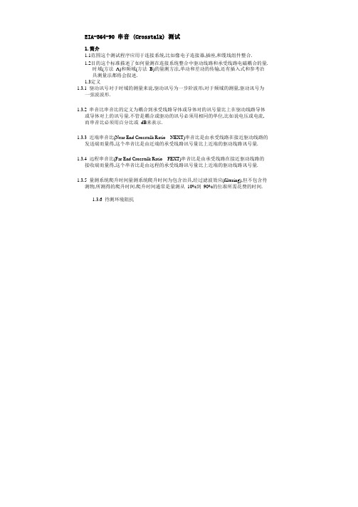
EIA-364-90 串音 (Crosstalk) 测试1.简介1.1范围这个测试程序应用于连接系统,比如像电子连接器,插座,和缆线组件整合.1.2目的这个标准描述了如何量测在连接系统整合中驱动线路和承受线路电磁耦合的量.时域(方法A)和频域(方法B)的量测方法,单动和差动的传输,还有插入式和参考治具测量法都将会叙述.1.3定义1.3.1 驱动讯号对于时域的测量来说,驱动讯号为一步阶波形;对于频域的测量,驱动讯号为一弦波波形.1.3.2 串音比串音比的定义为耦合到承受线路导体或导体对的讯号量比上在驱动线路导体或导体对上的讯号量.不管是耦合或驱动的讯号必须用相同的单位,比如说电压或电流,而串音比必须用百分比或 dB来表示.1.3.3 近端串音比(Near End Crosstalk Ratio – NEXT)串音比是由承受线路在接近驱动线路的发送端而量得,这个串音比是由近端的承受线路讯号量比上近端的驱动线路讯号量.1.3.4 远程串音比(Far End Crosstalk Ratio – FEXT)串音比是由承受线路在接近驱动线路的接收端而量得,这个串音比是由远程的承受线路讯号量比上近端的驱动线路讯号量.1.3.5 量测系统爬升时间量测系统爬升时间为包含治具,经过滤波效应(filtering),但不包含待测物,所测得的爬升时间.爬升时间通常是量测从 10%到90%的位准所需花费的时间.1.3.6 待测环境阻抗阻抗是由治具上的传导讯号导体所呈现.阻抗是由传输线,终端电阻,接收端,讯号来源和治具寄生效应的结果.1.3.7 步阶振幅如图一所示,步阶振幅是从 0% 到 100% ,忽略 overshoot 和 undershoot, 的电压差值.1.3.8 隔离标准板(Isolation Standard)隔离标准板为一没有待测物,但与测试治具有相同的串音特性的参考治具,这个治具可以为或可以不为测试板的一部份.1.3.9 终端连接在传输线末端的阻抗,通常是为了减小在传输在线的反射能量.2.测试资源2.1设备2.1.1 方法 A,时域2.1.1.1步阶讯号产生器连接于驱动线路,而承受线路则连接于示波器.如果是差动讯号的应用,则步阶讯号产生器和示波器都必须要有处理差动讯号的能力,这表示输出端要能调整振幅和 skew的差异,而输入端要能显示两个输入讯号的差跟和,为了能更改不同的爬升时间,仪器要提供滤波(filtering)或归一化(normalization)的功能.在这种情况下,时域反射仪(TDR)通常会被采用.2.1.1.2 探针当探针被采用的时候,必须要有合适的爬升时间表现和负载电路特性.2.1.2 方法B,频域网络分析仪(Network Analyzer)是较为偏好的,当需要较大的动态范围(dynamic range)时,讯号产生器和频谱分析仪的组合也可为替代的方案.一个八端口的网络分析仪或baluns可用来做差动讯号的测量.2.2治具除非在参考文件中有其他特别规定,否则待测物环境阻抗必须要匹配测试设备的阻抗.通常单动 (single-ended) 量测要求 50奥姆的阻抗而差动(differential) 量测要求 100奥姆.2.2.1 待测物导体配置对于每一个测量,驱动线路和承受线路必须如参考文件所示而摆置,如果可能的话,邻近于待测线路的线路必须做终端(terminated)的动作.除非有其他特别的规定,否则采用 1:1的讯号对接地的比例(如果是做差动讯号的测量,则采用一对差动讯号线路对应一个接地线路),所有的线路都对应到相同的接地面,如图二所示.治具必须设计成所有的线路有相同的时间延迟.注意–当驱动讯号为差动的模式且非均衡时,则共模(common mode)讯号的能量必须被终端(terminated)图二2.2.2 终端驱动线路的远程和承受线路的两边末端都必须用待测环境阻抗做终端,所采用的方法可以参考图三或图四,如果待测环境阻抗和测量设备的阻抗不匹配的话,可使用匹配电路(matching network),在整个的频率量测范围内必须注意到尽量减小电阻性终端的电抗效应.注意–治具的几何形状和材质会影响到测量肇因于治具的寄生效应,所以通常以产品的用途来规划最有意义的治具形态.图三单动模式测量的阻抗终端图四差动模式测量的阻抗终端2.2.3 串音从待测物所量得的串音中分离出治具的串音是困难的,所以参考文件必须规范治具以使治具所产生的串音量减到最小.注意–因为测试板的脚位布局或缆线组件整合的终端技术会严重地影响到串音量,所以建议治具应包含隔离标准板(Isolation Standard)2.2.4 插入式技术治具(Insertion Technique Fixture)这种治具必须设计成不管有没有加入待测物都可以做串音的测量,如图五所示,如果为了双动测量(balanced measurement)而使用baluns,或为了阻抗匹配而使用最小损耗垫(minimum loss pads),如图三和图四所示,这些都包含在治具2.2.5 参考治具技术(Reference Fixture Technique)使用这种技术一个个别包含有近端和远程的治具将会被用来做治具串音的测量,这个治具,除了没有待测物外,将是待测物治具的复制品;如果有电路线路的话,必须包含治具的连接器,贯孔,弯折(bends),和转角(corners);如果为了双动测量(balanced measurement)而使用baluns,或为了阻抗匹配而使用最小损耗垫(minimum loss pads),如图三和图四所示,这些都包含在治具之中.之中.3.待测物3.1叙述这项测试的待测物必须有一条以上的讯号线,而且必须为下列对象之一:一.1.1可分离的连接器接合一起的连接器配对.一.1.2缆线整合组件附有连接器或接合在一起的连接器配对的缆线.一.1.3插座插座和测试组件,或插座和可插入的转接头.一. 4.测试步骤一.驱动线路的远程和承受线路的两端都必须用待测环境阻抗做终端,终端的方法可用图三和图四的其中一种.一.4.1方法A,时域一.4.1.1一般性原则一.4.1.1.1待测物必须放置距离会影响测量结果之对象至少 5cm 远之处.一.4.1.1.2 参考测量和治具串音一.4.1.1.2.1量测并纪录从10%到90%位准的量测系统爬升时间,除非参考文件有其他任何的规范.一.4.1.1.2.2治具的串音会添加在待测物的串音中,如果有使用最小损耗垫,那么最小损耗垫也包含在治具之中;如果参考文件明确地描述治具,那么治具所贡献的串音量即为已知值,则治具串音的测量就是非必须的;这些结果是量测量对时间的关系图,用以下的其中一种技术来量测量测系统爬升时间,驱动线路振幅,和治具串音量.一.4.1.2插入式测量法一.4.1.2.1在不加入待测物的情况下,把治具的近端和远程连接起来,将示波器和脉冲讯号产生器连接在驱动线路治具的适当位置;对多个同步驱动讯号线路,匹配它们的振幅,并且减小它们之间的 skew;对双动讯号的测量,减小这对线路的skew,量测并报告 skew的值.一.4.1.2.2如果同步要被驱动的线路数目超过了设备的容许值,或者频道间 skew的排除是一件令人担心的事,那么一次驱动一条线路且串音量以迭加(superposition)的方式纪录下来.一.4.1.2.3量测驱动讯号在通过治具时的步阶爬升时间和振幅(如果有要求,这个动作可以使用加上待测物的治具来完成),调整滤波功能使得量测爬升时间符合要求的值,或如表一的值.表一4.1.2.4依照参考文件将示波器连接于承受线路,测量将待测物移除的治具串音量,将治具串音振幅除以步阶讯号振幅以求得治具串音比并将其表示成百分比的形式,除非有其他的规范,否则将峰值和符号给纪录下来.4.1.3 参考治具测量法4.1.3.1将示波器和脉冲产生器连接在驱动线路的适当位置;对于双动讯号的测量,讯号源必须使正向和负向的步阶讯号振幅一致,且将其 skew移除;对于多个同步驱动讯号线路,使其振幅一致且移除 skew.4.1.3.2如果同步要被驱动的线路数目超过了设备的容许值,或者频道间 skew的排除是一件令人担心的事,那么一次驱动一条线路且串音量以迭加(superposition)的方式纪录下来.4.1.3.3量测驱动讯号在通过参考治具时的步阶爬升时间和振幅(如果对远程串音有要求,这个动作可以使用加上待测物的治具来完成),调整滤波功能使得量测爬升时间符合要求的值,或如表一的值.4.1.3.4如参考文件所示,将示波器连接在参考治具的承受线路上,量测承受线路接收到的最大振幅,把这个值减去在驱动讯号产生前承受线路上的讯号振幅以便获得承受线路的串音量(包含符号),将承受线路的串音量除以步阶讯号的振幅以计算治具串音比,并将其表示成百分比的形式.4.1.4 待测物串音测量4.1.4.1在治具上加入待测物.4.1.4.2将示波器连接在承受线路被要求的位置,而同样的,把步阶讯号产生器连接在驱动讯号线路被要求的位置;对于双动讯号的测量,讯号源必须使正向和负向的步阶讯号振幅一致,且将其 skew移除;对于多个同步驱动讯号线路,使其振幅一致且移除 skew.4.1.4.3如果同步要被驱动的线路数目超过了设备的容许值,或者频道间 skew的排除是一件令人担心的事,那么一次驱动一条线路且串音量以迭加(superposition)的方式纪录下来.4.1.4.4量测承受线路接收到的最大振幅,把这个值减去在驱动讯号产生前承受线路上的讯号振幅以便获得承受线路的串音量(包含符号),将待测物-与-治具的承受线路的串音量除以步阶讯号的振幅以计算待测物-与-治具的串音比,并将其表示成百分比的形式.注意-当治具的串音量接近于待测物-与-治具的串音量时,对于结果的解释就要小心了,从这项测试减去治具串音并不是正确的做法.。
EIA-364-D中文

Qualification Procedure-Sequence
• 此建議測試順序是最低限度要求,適 用所有的等級。 • 依照不同應用,特定測試項目可自 測試順序、補充測試、及/或接合測 試項中增加或刪除。
Qualification Procedure-Sample Size
測試件應含對應端。每一特性量測的數據數量應為 測試件25%的端子量,但不應低於25筆數據。若低於 25筆數據,則所有端子必頇量測; 若還不足25筆,就 必頇提供額外的測試件。
EIA-364-D目的/範圍
針對電子連接器及插座建議基本的 (recommended minimum) 測試次序(Sequence) 及方法(Procedures) 依照預定的應用環境分級, 以便對每一分級能 作合適的評估 定義各環境分級的儀器操作狀況, 包含溫度與 溼度的最大範圍, 以及海洋氣候與嚴苛環境之 可能性
Contact resistance at rated current shall be used in those applications where the current levels are in excess of 100 milliamperes and the voltage levels are in excess of 3.0 volts. 選定電流的電阻測試(CRRC)用於 I>100mA & V>3V.
Qualification Procedure-Sequence
Visual examination shall be performed on the test specimens initially and after each environmental and stress test. Unless otherwise specified, unmating of the test specimens shall not be permitted until completion of the test sequence. The referencing document shall specify if the test specimens are to be unmated after vibration, physical shock and salt spray for visual examination. If not specified, the test samples shall remain mated.測試前後的外觀檢驗之必要性與解除互配狀態之許可. Unless otherwise specified, IR and/or DWV shall be tested between the closest spaced contacts (adjacent and/or between rows). Six contact pairs or 25% of the positions whichever is greater shall be tested per specimen. In the event that hardware and/or metal shells are used, the test shall also be performed between the metal accessories and the contacts closest to them in accordance with EIA-364-20 and/or EIA-364-21. IR與DWV之 測試點數量要求6對或25%的端子, 及端子與鐵殼/其他鐵件之測試 必要.
EIA-364连接器专项测试标准简介
Firewall Flame Test Procedure for Electrical Connectors
EIA-364-46B
MICROSECOND DISCONTINUITY TEST PROCEDURE FOR ELECTRICAL CONNECTORS,CONTACTS AND SOCKETS
Thermal Shock (Temperature Cycling) Test Procedure for Electrical Connectors and Sockets
EIA-364-35B
Insert Retention Test Procedure for Electrical Connectors
EIA-364-90
Crosstalk Ratio Test Procedures for Electrical Connectors, Sockets, Cable Assemblies or Interconnect Systems
EIA-364-91A
Dust Test Procedure for Electrical Connector and Sockets
EIA-364-56C
Resistance to Soldering Heat Test Procedure for Electrical Connectors and Sockets
EIA-364-59A
LOW TEMPERATURE TEST PROCEDURE FOR ELECTRICAL CONNECTORS AND SOCKETS
EIA-364-95
Full Mating and Mating Stability Test Procedures for Electrical Connectors
常规工程连接器Q test测试说明
CONNECTOR DIVISIONAPPLE連接器產品常规Q-test测试说明EIA-364 (美国电子工业学会)EIA-364(CONNECTOR DIVISION1. Low Level Contact Resistance (LLCR) 低阶接触阻抗2. Insulation Resistance 绝缘阻抗3. Dielectric Withstanding Voltage 耐电压4Temperature rise电气性能 4. Temperature rise温升5. 其它电气特性:电磁干扰泄露衰减;特性阻抗;插入损耗;反射系数,电压驻波比;串扰,传输延迟;时滞。
1. Mating/ unmating Force 插拔力2. Durability 寿命测试3. Contact retention force 端子保持力4. Contact normal force常规三机械性能端子正向力5. Vibration振动测试6.Physical shock振动冲击测试大测试1. Heat Soak 热储存测试2. Thermal Cycling 热循环测试3. Thermal Shock 冷热冲击测试环境性能冷热冲击测4. Humidity Cycling 温湿度组合循环测试5. Temperature Life 高温测试6.Salt Spray 盐雾测试7. Resistance to Soldering Heat 耐焊接热CONNECTOR DIVISION1.Low Level Contact Resistance (LLCR) 低阶接触阻抗测试1定义:1.任何金屬表面可能有a.灰塵b.氧化物c.油污等雜質, 當兩金屬表面接觸後該介質會影響電流之流通, 一般稱之為接觸阻抗. 高品质的连接器应当具有低而稳定的接触阻抗,连接器的接触阻抗从几毫欧到数十毫欧不等。
2.目的:在不破坏端子表面的氧化膜的情况下,测试结合的两个端子之间的接触阻值,以作为连接器端子的总体性评估.3. 方法:a)以四线量测法量测结合端子之电阻值b)测试电流:100mA max b)测试电流100mA max c)测试电压:DC 20mV max备注:常规CR测试电流和电压: DC 5V ;1A .4.参考标准:EIA-364-235测试仪器微欧姆机5.测试仪器:微欧姆机(设备自身就应具备四线法测试功能,它应有四个外接插孔。
- 1、下载文档前请自行甄别文档内容的完整性,平台不提供额外的编辑、内容补充、找答案等附加服务。
- 2、"仅部分预览"的文档,不可在线预览部分如存在完整性等问题,可反馈申请退款(可完整预览的文档不适用该条件!)。
- 3、如文档侵犯您的权益,请联系客服反馈,我们会尽快为您处理(人工客服工作时间:9:00-18:30)。
T E N T53standspecifiedseveritiesofvibration.件承受特定强度振动的能力。
quencyrangesandmagnitudesthatmaybeencounteredduringthelifeoftheconnector.振动幅度的环境,以此验证对产品性能的影响情况.icatesapictorialviewoftheaxisdefinitions.Thereferencingdocumentshal lindicatethefixturingrequiredortheaxisdefinitionsifdiffe 的轴向与图1不同,则在相关参考文件中需对试验装置要求及轴向进行定义。
对于具有对称性,方形及不规则的连接eandgeographiclatitude.hevibrationsystemconsistingofthevibrationmachine,togetherwithitsauxiliarytestequipment,shallbecapableofgeneratingeitheras 试设备,整个系统应能产生正弦或随机振动。
amplitudedistribution,exceptthattheaccelerationmagnitudesofthepeakvaluesmaybelimitedtoaminimumofthreetimestherms[thre 可限emblyofthesample.Ifnormalconnectormatingisdependentuponforcesexternaltotheconnector,thensuchforcesandmountingarrang 接器的连接方式需要依靠外力,那么这些外力与连接方式应尽可能模拟实际的状况(例如:印刷电路连接器)。
若是hetestfixtureshallbedesignedsothatresonantvibrationinherentinthefixturewithinthefrequencyrangespecifiedforthetestshallbemi elyaspossiblethenormalmountingofthespecimen.Aminimumof200mm(approx8in)ofwireorcableshallbeunsupportedonbothend donthemountingfixtureintheproximityofthesupportpointsofthespecimen.有共振频率在试验所规定的频率范围内达到最小。
在试验夹具上接近样品的地方监控所施加的振动强度。
样品安装应撑点的地方监控振动输入。
noftheappliedvibrationmotionshallbespecifiedinoneormoredirections.Iftheorderofapplicationofthedifferentdirectionsiscritical,i imensions,thematerials,temper,etc.,asapplicable.的方向。
如果朝不同方向施加的次序很重要,那就应该规定不同方向的先后顺序。
对于进行试验所要求的任何特殊试t.lliamperes,maximumforallcontacts.eaterdurationareallowed.Adetectorcapableofdetectingthespecifieddiscontinuityshallbeused.大于maximumamplitudemorethantwicethatofthesupportpoints.Whenspecified,resonantfrequenciesshallbedeterminedeitherbymonit 点的振幅的2倍还要大.当有规定时,共振频率应采用监控参数的方法,或采用共振检测仪的方法来确定共振频率。
oubleamplitude(maximumtotalexcursion),thefrequencybeingvarieduniformlybetweentheapproximatelimitsof10Hzand55Hz.T ulardirections(totalof6hours).Ifapplicable,thistestshallbemadeunderelectricalloadconditions.围内(从10至55,再从55至10)约历时1分钟.除非另有规定,在相互垂直的三个方法上各振动2小时(总共6小时).如果适用,振tothevibrationamplitude,frequencyrange,anddurationspecifiedandandrespectively;seefigures2and3.时间的振动,见图2和图3(0.06in)doubleamplitude(maximumtotalexcursion)or98.1m/s2(10g n)peak,whicheverisless.Thetoleranceonvibrationamplitudes 个振幅的容许误差为±10%.500Hz(seeexceptthattheprocedure(seeofthisstandardmaybeappliedduringthe10Hzto55Hzbandofthevibrationfrequencyrange. 规定的程序进行.cycleshallbeperformed12timesineachofthreemutuallyperpendiculardirections(totalof36times),sothatthemotionshallbeappliedf oingtothenextband.Whentheprocedure(seeisusedforthe10Hzto55Hzband,thedurationofthisportionshallbesameasthedurationfor循环12次(总共36次),因此整个试验过程历时9小时.只要能满足振动频率及速度的变化和总的试验时间要求,就允许试验每一个方向约1.33小时).tothevibrationamplitude,frequencyrange,anddurationspecifiedinrespectively;seefigures2and3.个.振幅的容许误差为±10%.。
000Hz(seeexceptthattheprocedure(seeofthisstandardmaybeappliedduringthe10Hzto55Hzbandofthevibrationfrequencyrange. 规定的程序进行。
iscycleshallbeperformed12timesineachofthreemutuallyperpendiculardirections(totalof36times),sothatthemotionshallbeapplied egoingtothenextband.Whentheprocedure(seeofthisstandardisusedforthe10Hzto55Hzband,thedurationofthisportionshallbethesa各循环12次(总共36次),因此整个试验过程历时12小时.只要能满足振动频率及速度变化和总的试验时间要求,就允许相垂直的每一个方向约1.33小时)。
othevibrationamplitude,frequencyrange,anddurationspecifiedinandrespectively;seefigures2and3.(0.06in)doubleamplitude(maximumtotalexcursion)or196.1m/s2(20g n)peak,whicheverisless.Thetoleranceonvibrationamplitud 个.振幅的容许误差为±10%。
规定的程序进行。
iscycleshallbeperformed12timesineachofthreemutuallyperpendiculardirections(totalof36times),sothatthemotionshallbeapplied上变化和总的试验时间要求,就允许试验间断进行。
eprocedure(seeofthisstandardisusedforthe10Hzto55Hzband,thedurationofthisportionshallbethesameasthedurationforthisbandu 的程序进行振动时,这一频段持续的时间与采用对数循环的时间相同(在三个互相垂直的每一个方向约1.33小时)。
aximumfrequencytotheminimumfrequencyineachbandshallbenotlessthantwo(2).之比不小于2。
beapproximatelyequal.ividedintothreebands,55Hzto125Hz,125Hzto500Hzand500Hzto2,000Hz,inaccordancewithForeachband,lettheconstant, entheratesofchangeforthethreebandswillbe125κ,500κand2,000κ,respectively.Thetimes(inminutes)totraversethethreefrequ zperminute,34.2Hzperminuteand137Hzperminute,respectively.Theminimumtimesoftraverseofthebandsare8.2min,10.9minand 频段,令频率的变化率与该段频段的最高频率之比值为k,则三个频段的频率变化率分别为125k、500k及2000k,各频频率变化率分别为8.55Hz/分钟、34.2Hz/分钟和137Hz/分钟,经过三个频段的时间分别为8.2分钟、10.9分钟和10. requency;seeThespectral-densityvaluesshallbewithin+40%and-30%(±1.5dB)ofthespecifiedvaluesbetweenalower-specifiedfr dwidthwillbeamaximumof1/3-octaveorafrequencyof25Hz,whicheverisgreater.z之间时,频谱密度的值应介于规定值的+40%和-30%以内(±1.5dB).频率位于1000Hz与上限频率(2000Hz)之间时,频runit-filterbandwidth.Forthisapplicationitisexpressedasg2/f,whereg2/fisthemean-th.Thespectraldensitycurvesareusuallyplottedeitheronalogarithmicscale,orinunitsofdecibels(dB).Thenumberofdecibelsisdefin ue.是滤波器带宽的每一次循环周期中所通过的以重力单位表示的加速度均方值.频谱密度曲线通常以对数坐标或以分贝),gr2/f为给定的参考频谱密度,通常为所给定的最大值。