
百特重油燃烧器技术手册
百特重油燃烧器技术手册
摘要:本文档旨在为用户提供百特重油燃烧器的详细技术信息和操作指南,以便用户能够更好地了解该产品,并正确地进行安装和维护。
该手册包含了百特重油燃烧器的结构组成、工作原理、安装要求、操作步骤、维护注意事项等内容。
同时,该手册还提供了常见故障排除方法和技术规格等相关内容,以供用户参考和使用。
第一部分:产品概述
1.1 产品简介
本章主要介绍百特重油燃烧器的基本概念、特点和应用领域,为用户提供了对该产品的整体了解。
1.2 技术规格
本节列举了百特重油燃烧器的主要技术规格,包括功率范围、燃油供应压力、燃烧效率等参数。
1.3 产品结构
本节详细描述了百特重油燃烧器的结构组成,包括主体部分、控制系统、燃油系统、热风系统等。
第二部分:工作原理
2.1 燃油供应系统
本节详细介绍了百特重油燃烧器的燃油供应系统,包括燃油泵、喷嘴和油气调节阀等相关设备。
2.2 燃烧过程
本节详细描述了百特重油燃烧器的燃烧过程,包括预混合燃烧
和过量空气燃烧等相关原理。
2.3 控制系统
本节介绍了百特重油燃烧器的控制系统,包括点火控制、燃烧
控制和温度控制等相关内容。
第三部分:安装与调试
3.1 安装要求
本节列举了百特重油燃烧器的安装要求,包括选址要求、安装
位置、通风要求等。
3.2 安装步骤
本节详细描述了百特重油燃烧器的安装步骤,包括固定、连接
管路、接线等操作。
3.3 调试检查
本节介绍了百特重油燃烧器的调试检查步骤,包括点火测试、
燃烧效果检查等。
第四部分:操作与维护
4.1 操作步骤
本节详细描述了百特重油燃烧器的操作步骤,包括启动、运行、停机等操作。
4.2 维护注意事项
本节列举了百特重油燃烧器的维护注意事项,包括定期清洗、
润滑和更换易损件等维护操作。
4.3 常见故障排除
本节提供了百特重油燃烧器常见故障的排除方法和处理建议,
以便用户在故障发生时能够迅速解决。
结论:本文档详细介绍了百特重油燃烧器的技术细节和操作指南,为用户提供了全面的使用帮助。
用户通过学习本文档,能够更
好地了解该产品的工作原理和安装调试要求,并正确地操作和维护
百特重油燃烧器,确保其安全高效运行。
同时,本文档还为用户提
供了常见故障排除方法,以便用户能够在故障发生时快速解决问题。
baltur燃烧器TBG210P17690030中文使用维护手册

• 2014/35/CE (D.B.T.)
• 2006/42/CE (D.M.)
符合以下欧盟标准: • prEN 676:2008(燃气和混合燃料,燃气部分)
• prEN 267:2008(混合燃料,柴油侧)
• EN 60335-1 (2012-01) + EC (2014-01).
1 / 34 0006081523_201711
制造商声明
CE0085: DVGW CERT GmbH, Josef-Wirmer Strasse 1-3-53123 Bonn (D) 兹声明,我们的燃气和混合燃料吹气式燃烧器系列: BPM...; BGN…; BTG…; TBML...; Comist…; GI…; GI…Mist; Minicomist…; Sparkgas...; TBG..; IB..; TBR... (改型产品:... LX,用于低NOx排放;-V用于逆变器,FGR用于烟雾的外部再循环) 符合欧洲指令和法规所规定的最低要求: • 2009/142/CE - (UE) 2016/426 (D.A.G.) (R.A.G.)
危险/注意 此标记表示极端危险。如忽略它们,有可能会严 重影响身体健康或威胁人身安全。
小心/注意事项 此标记表示应采取适当的措施来避免健康和安全 受到影响,以及不让经济受到损失。
重要事项 此标记表示某些不容忽略的重要技术和操作信 息。
存储条件及时长 设备由制造商经过包装进行发货并且使用橡胶垫进行 运输,使用海运以及其他符合运输标准的运输方式。 对于不使用的设备,需要存放在封闭区域并确保标准 空气流通条件(温度在-10°C到+ 40°C)。 存储时期为3年。
调校和维护开始注意事项 • 只允许有资质的专业技术人员在符合现行规范的情
燃油燃烧机使用说明书
燃烧器在调试完成后即可投入正常使用,日常操作按以下步骤进 行: 1、检查:确认设备系统的启动准备是否已就绪。确定后接通燃料、 气路和电源。 2、启动:打开电源开关启动燃烧器,通过外接控制启动运行。燃烧 器将根据设备控制装置控制自动进行大小火转换。 3、停机:如需停止运行,可按下急停按钮,关闭电源开关即可停机。 长时间停机时应关闭油路阀门及切断电源供应以确保安全。
注:点火失败或意外熄火引发燃烧机故障报警后,需排除故障后重新 启动。
维护与检修
为保证燃烧器安全,正常使用,应经常或定期对燃烧器进行维护
6
邢台方日通用设备有限公司
和保养,出现故障时应及时检修。因维护,检修可能影响到燃烧器的 正常工作.请务必由合格的技术人员进行操作。 1、经常检查燃烧器及其各部件的连接是否紧固,位置有无变化。 2、每次开机前检查电源电路及气路是否异常以及启动运行过程中有 无异常。 3、经常检查油料供应是否正常,燃烧是否良好,控制系统是否灵敏。 4、注意燃烧器工作环境应清洁,干燥,尤其是电路部分不得受潮, 受高温。 5、如装置过滤器应定期清洗.保证燃料通路畅通。 6、定期清洁点火针,火焰监测器(离子针)及喷油嘴。 7、定期监测燃料喷嘴,点火针及稳焰盘位置是否变化,清理结垢或 积炭。 8、定期进行整体检查,保养。 9、经常检查电磁阀有无泄漏情况,如有应立即检查阀密封面磨损及 阀芯是否被异物卡死,必要时更换新阀。 10、定期拆洗燃油过滤器,使其处于清洁状态如滤网有损坏应立即 更换新滤网,尤其是开始使用阶段更要注意。 11、检查清洁点火电极和离子针:修正其位置如有损坏应及时修理 或更换 12、让燃烧器在非水冷炉膛中使用时,在燃烧器停机期间为防止炉 膛高温辐射损坏燃烧器,应采用适当保护措施。
标准和规范要求。本手册中有“危险”、“注意”等符号说明的地方请
燃烧器说明书

燃烧器说明书目录1、燃料2、制粉系统与煤粉管道3、百叶窗式水平浓淡分离燃烧器4、燃烧器安装和调整中的注意事项5、伸缩式油枪(简单机械雾化)6、常规点火油、蒸汽、空气管路(见供货厂家相关说明)7、微油点火及暖风器系统(见供货厂家相关说明)8.点火操作(常规说明,详见供货厂家相关说明)9、煤粉燃烧器的操作运行附图参考图纸1、燃料本工程为山东魏桥创业集团有限公司、山东魏桥铝电有限公司1217t/h供热机组锅炉,所用燃料如下:1.1、煤质分析资料:1.1.1 品种:贫煤1.2 燃油,0#轻柴油特性如下:粘度(20℃)恩氏粘度°E 1.2~1.67运动粘度mm2/s 3.8~8.0灰份,不大于 0.25%硫含量,不大于 0.25%水份,不大于痕迹C16H34 不小于 50%闪点不低于65℃凝固点不高于0℃低位发热量 41870kJ/kg(10000kcal/kg)2、制粉系统与煤粉管道2.1制粉系统本机组采用双进双出钢球磨正压冷一次风机直吹式,每台锅炉配三台MGS-4360型磨煤机,一台磨煤机对应二层一次风。
煤粉细度R90=6%。
,炉前原煤由储煤斗经过给煤机进入磨煤机两端的原煤入口,借助螺旋输送装置将原煤送入磨煤机筒内。
热风通过磨煤机两端中空轴内的热风管道进入磨煤机,热风携带煤粉通过磨煤机两端中空轴和热风管之间通道由输粉管道进入分离器,经分离合格的煤粉连同干燥介质形成风煤混合物(一次风)经煤粉管道输送至燃烧器进入炉膛内进行燃烧,不合格的煤粉返回磨煤机再次碾碎。
磨煤机出口风量(即一次风总量)由通过磨煤机的风量和旁路风量之和。
MGS-4360型双进双出磨煤机允许采用不对称运行方式,即从磨煤机一端进煤而在磨煤机一端或二端出煤粉,可以实现半台或一台磨煤机运行。
磨煤机的性能和运行请仔细阅读供货厂家说明书。
2.2煤粉管道2.2.1煤粉管道的布置本机组配三台磨煤机,于锅炉前呈一排布置。
由每台磨煤机两端出来的风粉混合物经2×4根煤粉管道引至两层四角煤粉燃烧器的两层煤粉喷嘴。
燃烧器说明书(中英文)
二级点火 Two Classes Ignition
角执行机构 Angle Action Device
400Nm,220V,4~20mA 控制电流 Control Current
四、安装与调试 Installation and Regulation 1、燃烧器安装 燃烧器上安装法兰与炉墙上预留的安装法兰用 12 只 M16×50
After regulation, close the box tightly, and protect it from dust.
五、操作步骤 Operation Steps 1、点火 Ignition (1)点火:检查油管路系统,将各手动阀置于开位。启动电动推进器按钮,将
点火枪送至油枪前端。将风油联动系统开度至 40%处,启动高能点火器点火按钮使其 点 火 , 接 着 打 开 燃 烧 器 前 的 点 火 油 枪 进 油 电 动 阀 , 此 时 燃 油 即 开 始 雾 化 燃 烧 。( 高 能 点火装置连续工作时间不能超过 30 秒),火焰稳定后火检着火信号反馈,主油枪进油 电动阀和回油电动阀打开,主油枪燃油雾化燃烧,点火油枪进油阀关闭,火检信号反 馈稳定,点火成功!(油枪前压力保证 2.8~3.5MPa)。 Ignition: check oil pipeline, and open all the manual valves. Press electric actuator start button, and advance spark rod to oil gun front. Open the air and oil regulator to 40%. Press HEA exciter ignition button, and open the oil inlet electric valve of ignition oil gun in front of burner, then the fuel is atomized combusting (the HEA exciter may not work over 30s continuously). The flame on signal is sent from flame scanner when the combustion is stable. Open oil inlet electric valve and oil return electric valve of main oil gun. Oil in the main oil gun is atomized combusting. Close oil inlet valve of ignition oil gun. When signals from flame scanner indicate stable
百特油气联合燃烧器说明书

油燃烧器(安装操作)说明书目录一、适用范围 (2)二、设计数据 (2)三、安装要求 (2)四、操作及维护 (4)五、故障排除 (5)六、附件资料 (7)一、适用范围1、此说明书供安装及使用单位参考。
2、该型油气联合燃烧器是加热炉的燃烧设备。
适用于安装在燃烧器前风压≤245Pa(25mmH2O)的机械通风,或自然通风。
3、于热风系统时,空气温度不应超过350℃,以避免产生过大的变形和燃料油严重析炭。
二、设计数据1、设计参数-参考本公司提供的安装图三、安装要求1、开箱验收。
燃烧器在安装之前应由操作使用单位进行开箱验收,并将备件存放好,以免施工时期丢失。
验收的主要项目是:(1) 装箱单、质量合格证明书和安装图是否齐全。
(2) 装箱件数及备件是否与装箱单相符。
(3) 燃烧器铭牌及喷头上的钢印标记是否与合同要求相符。
(4) 与炉子及风道连接的螺栓孔的孔数、孔径及位置等是否与图纸相符。
(5) 风门及调节手柄是否灵活可靠。
(6) 钻屑和毛刺是否清除干净。
(7) 油喷嘴枪上的接口是否与安装图相符。
2、安装燃烧器应按要求安装,以便在低过剩空气水平下得到良好的燃烧状况。
安装不合适将导致燃料—空气混合不良影响火焰稳定。
耐火砖作为空气流通的一部分,安装不合适将使得助燃空气偏流,导致火焰不均衡和发飘。
安装前的准备工作2.1.1 切断所有燃料供应线。
2.1.2 所有通道放置“炉内有人”标示,保证燃料供应阀和燃料线在断开位置。
2.1.3 炉子入口处有人值守。
2.1.4 进入前置换炉膛,置换空气量至少为炉膛体积的5倍,时间不少于15分钟。
2.1.5 工作人员在炉内时,烟囱挡板应在全开位置。
燃烧器的安装2.2.1 拆去燃烧器运输过程中的所有包装物,检查所有零部件有无缺损。
检查完毕后应将喷头及长明灯喷口包好,以免现场施工过程中把喷口堵塞。
2.2.2按燃烧器安装图与炉底连接形式把燃烧器固定好,保持燃烧器垂直于炉内表面。
2.2.3烧嘴砖安装前要预组装,安装时烧嘴砖应保证与燃烧器同轴,其同轴度偏差应不大于2mm;砌砖筑应磨砖对缝,砖缝不应大于2mm。
维修手册-燃烧器
燃烧器部分大庆油田真空加热炉配套使用的燃烧器种类比较杂,油田装备制造集团选用的是上海凌云的豪迈德(hofamat)和无锡赛威特的曼格奈特(magnet),油田应用的还有冀东石油机械公司的新远、意大利的百得(batur),这几种是较为常见的。
瑞典的奥林(olin)、法国的贵诺(guino)等都比较少。
本手册所述燃烧器部分,是指包括燃烧器机体、程控器、点火变压器、燃烧头、点火管、风机、叶轮、伺服机构、电磁阀组、调压器、过滤器以及风压、气压等各种开关组成的一个整体的燃烧系统。
所有种类的燃烧器,都有一个共同点,执行步骤都是先经过一定安全检测,再执行炉膛扫风,打火,电磁阀开启送气,点火,检测火焰,稳定一定时间后转火。
绝大多数的燃烧器都是依靠程序控制器来控制这些执行步骤,程序控制器带有安全自锁功能,确保每个执行步骤的安全进行。
程序控制器的程序执行,每一步都有各种条件检测,满足条件之后才执行下一步,并且有严格的时间设定。
通过这一严格时间保证下的程序执行,能迅速知道燃烧器执行到哪一步,出现故障时能迅速做出故障点判断。
它是燃烧器的核心部件。
燃烧器的售后维修,基本上都是以程序控制器为主线和指导进行的。
通常情况下,燃烧器的售后服务人员都是比较了解一种到两种燃烧器的维修技术,立足于这个基础以点及面破解和掌握其他品牌燃烧器的维修技术。
本手册也是基于这种想法,先以大庆油田装备制造集团选用的豪迈德(hofamat)燃烧器为基础进行讲解,探讨其使用原理,学习它的维修技术,以求贯通其他燃烧器维修技术。
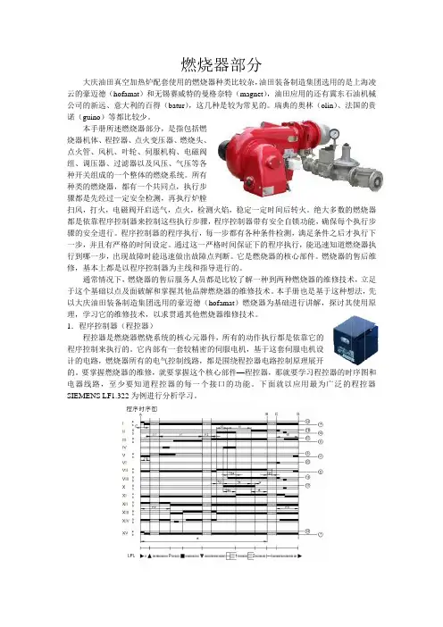
1.程序控制器(程控器)程控器是燃烧器燃烧系统的核心元器件,所有的动作执行都是依靠它的程序控制来执行的。
它内部有一套较精密的伺服电机,基于这套伺服电机设计的电路,燃烧器所有的电气控制线路,都是围绕程控器电路控制原理展开的。
要掌握燃烧器的维修,就要掌握这个核心部件—程控器,那就要学习程控器的时序图和电器线路,至少要知道程控器的每一个接口的功能。
燃烧器操作手册
燃烧器操作说明一、 初次使用,检查程序:遵循锅炉制造商的使用说明确认系统有足够多的水,油箱满油确认燃烧系统电控柜接线正确检查燃烧器电机转向检查温度、压力等传感器设定油路排气确保无空气检查油箱、油管、油泵充满油,喷嘴选择正确检查油路是否有泄露燃烧器处于开启位置,风门处于关闭位置程控器闭合,程控器处于启动位置二、 油路系统检查断开油路卸下电磁阀和喷嘴间连接启动燃烧器检查是否安程序控制器既定程序运行1、鼓风机气动2、风门伺服电机运行到最大位置3、风压监测正常4、风门伺服电机返回到点火位置5、点火6、油电磁阀打开7、安全时间后报警重新装好连接件三、 比例调节器回油与空气流量调节卸下风门伺服电机与比例调节器上的连接,启动燃烧器,点火后手动设定燃烧器负荷在最小位置,检查燃油和风量配合效果。
顺时针转动= 增加风量逆时针转动= 降低风量注意:燃烧器启动后调节风压开关,如果设定值过高,风压开关会自动保护,设定风压保护值一定要合理。
测量点火位置油消耗量1、通过流量表2、根据供油压力和喷嘴型号按照曲线图测算调节点火位置油量1、若喷油量过低,将伺服电机逐步增大到规定值2、若喷油量过高,现将最低油量限位开关调低,再逐步降低风门伺服电机,直至达到规定值。
调整过程中注意燃烧器的燃烧情况,如有必要从新调整。
调整满负荷耗油量逐步增大风门伺服电机的位置直至满负荷,调整过程中观察火焰燃烧情况,如有必要从新进行调整。
测量满负荷位置油消耗量1、通过流量表2、根据供油压力和喷嘴型号按照曲线图测算调节满负荷油流量若满负荷油量过多,减小风门伺服电机开度,直至达到规定值注意:不允许通过调节连杆降低油流量,以免影响低负荷燃烧状况。
若满负荷油量过低,首先增大限位开关的位置,然后调节伺服电机的开度,直至达到规定值,调节过程中注意观察火焰燃烧情况,如有必要从新进行调整。
风量调节风门伺服电机出厂设定值为:满负荷时全开,低负荷时全关,未达到最佳的燃烧效果,应从低负荷位置逐步调整燃油与风量的配比。
燃烧器说明书(中文)
1.2.5.燃烧空气控制板 燃烧器前面的空气口内装有一个风量控制挡板,它用于调节燃烧器的空气量。 总负荷分十个比例调节位置段,对应调节供风量,每段的斜率可调,使燃烧器处 于最佳状态。
1.2.6.火焰探测装置 燃烧器的主火焰由主火焰探测器来监测。 火焰探测器的连接管安装在燃烧器前板 上,它带有一个冷却空气接头。冷却空气可保持火焰探测器清洁并防止过热。 引导火焰由点火枪的电离杆探测。 1.2.7.观察孔 火焰和燃烧孔通过观察孔来观察。冷却空气流可防止观察孔过热和变脏。
注意: 这些操作和维修指导包括燃烧器制造商的一些资料,可通过使用单位的指导进行补充。 此燃烧器指导说明书,并不包括使用单位特定的工艺流程上的操作与维护的特殊资料,这 些资料需由使用单位制定。 这些特殊工艺的操作与维护资料优先于燃烧器的说明。
1.结构说明
1.1.交付说明
油气燃烧器 GKT-35S 墙式安装在锅炉上。 5 台油气燃烧器 Oilon GKT-35S 制造号:7083 , 7084 , 7085 , 7086 , 7087
当燃烧气体和空气的预混合物在喷嘴内经点火电极点燃时,燃烧产生。 警告:点火电压为 5000V 来自供给管路的液化气和燃烧空气按所需量通过阀装置进入点火枪。 点火枪供有连续的冷却空气流(见操作指导:冷却空气) 点火枪上装有一个机械限位器以保证燃烧器有正确的安装深度。 限位器用六角螺 钉固定在点火枪的框管上,正确安装深度(L1)测量值已记录在“设定值”一章 的表中。
目录
1. 结构说明……………………………………………………………………………………….1.1 1.1.交付范围………………………………………………………………………………1.1 1.2.GKT-35S 燃烧器……………………………………………………….……………1.1 1.3.阀组……………………………………………………………………………………1.4 1.4.自动控制………………………………………………………………………………1.4 2.技术数据……………………………………………………………………………………...2.1 3.操作指导………………………………………………………………………………………3.1 3.1.总述……………………………………………………………………………………3.1 3.2.装配检验………………………………………………………………………………3.1 3.3.第一次启动/长期关闭后的启动的准备工作…………………………………………3.2 3.4.正常运行……………………………………………………………………………….3.2 3.5.启动…………………………………………………………………………………….3.3 3.6.停止和紧急停止……………………………………………………………………….3.3 3.7.油调节装置…………………………………………………………………………….3.4 3.8. 冷却空气………………………………………………………………………………3.10 3.9. 燃烧空气………………………………………………………………………………3.10 3.10.故障排除…………………………………………………………………………….3.11 3.11. 油嘴功率表………………………………………………………………………….3.12 4. 设定值………………………………………………………………………………………….4.1 5.维修指导………………………………………………………………………………………5.1 5.1.总述…………………………………………………………………………………….5.1 5.2.油喷嘴的维修………………………………………………………………………….5.1 5.3.点火燃烧器…………………………………………………………………………….5.2 5.4.阀组…………………………………………………………………………………….5.2 5.5.关闭期间的维修……………………………………………………………………….5.3 5.6.润滑,垫片和轴承说明……………………………………………………………….5.4 5.7. 机器卡片……………………………………………………………………………….5.5 6.安全指导………………………………………………………………………………………6.1 7.安装指导………………………………………………………………………………………7.1
重油燃烧器操作和维护说明书
2916193 (0)61931GBINDEX1.BURNER DESCRIPTIONTwo stage heavy oil burner.1.1EQUIPMENTFlexible tubes . . . . . . . . . . . . . . . . . . . . . . . . . . . . . No. 2Nipples. . . . . . . . . . . . . . . . . . . . . . . .No. 2Gaskets . . . . . . . . . . . . . . . . . . . . . . . . . . . . . . . . . . . .No. 2Screws . . . . . . . . . . . . . . . . . . . . . . . . . No. 4Flange shield . . . . . . . . . . . . . . . . . . . . . . . . . . . . . . . .No. 1Nozzles. . . . . . . . . . . . . . . . . . . . . . . . . No. 2Guide extensions (for the lengthened head version).No. 2Gasket . . . . . . . . . . . . . . . . . . . . . . . . . No. 1Fitting for operation with emulsifiedoil fuel (see page 9) . . . . . . . . . . . . . . . . . . . . . . . . . .No. 11.BURNER DESCRIPTION. . . . . . . . . . . . . .11.1Equipment . . . . . . . . . . . . . . . . . . . . . . . . .12.TECHNICAL DATA . . . . . . . . . . . . . . . . . .22.1Technical data . . . . . . . . . . . . . . . . . . . . . .22.2Dimensions . . . . . . . . . . . . . . . . . . . . . . . .22.3Field of operation. . . . . . . . . . . . . . . . . . . 23.INSTALLATION . . . . . . . . . . . . . . . . . . . . .33.1Fuel oil supply systems . . . . . . . . . . . . . . . .33.2Electrical system . . . . . . . . . . . . . . . . . . . .43.3Electrical connections . . . . . . . . . . . . . . . .54.OPERATION. . . . . . . . . . . . . . . . . . . . . . . 64.1Choice of nozzles . . . . . . . . . . . . . . . . . . . 64.2Pump pressure . . . . . . . . . . . . . . . . . . . . . 64.3Combustion head setting. . . . . . . . . . . . . . . . 64.4Adjustment of the air damper motor . . . . . . . 64.5Air pressure switch . . . . . . . . . . . . . . . . . . . . 74.6Atomisation temperature adjustment . . . . . . . 74.7Start-up programme. . . . . . . . . . . . . . . . . . . . 94.8Ecological oil burners . . . . . . . . . . . . . . . . . . 94.9Emulsified fuel oil functioning . . . . . . . . . . . . 94.10Start-up programme diagnostic. . . . . . . . . . 104.11Operating fault diagnostics . . . . . . . . . . . . . 102893O The burner meets protection level of IP 40, EN 60529.O Burner with CE marking in conformity with EEC directives: EMC 89/336/EEC, Low Voltage73/23/EEC and Machines 98/37/EEC.1-Suction line 2-Return line3-Pump pressure adjustment screw 4-Manometer fitting (G1/8) 5-Vacuometer fitting (G1/2) 6-Air damper opening motor7-Control box reset push-button and lock-out indication8-Fan overload cutout reset9-Combustion head regulating screw 10-Double filter11-Valve assembly12-Manometer with protection valve 13-Adjustment thermostat 14-Pre-heater contact maker 15-Ignition transformer 16-Terminal strip 17-Cable glands 18-Antigas valve 19-Thermometer20-Pump motor starter with reset 21-Air pressure switchFig. 161932GB2.TECHNICAL DATA2.1TECHNICAL DATA2.2DIMENSIONS2.3FIELD OF OPERATION (2 nozzles in operation)TYPE627 TThermal power - Flow rate 114/205 - 513 kW – 10/18 - 45 kg/hFuelOil with max. viscosity at 50° C 115 sq. mm/sec (15° E)Electrical supply Three-phase,230V ± 10%~ 50Hz without neutral400V ± 10% ~ 50Hz with neutralMotor230V - 400VFan: 2.4A - 1.4A Pump: 2.1A - 1.2AIgnition transformer Primary 2 A – Secondary 2 x 6.5 kV – 35 mA Heaters2.8 kW Electrical intake power 4.1 kWPump60 kg/h at 20 barD2715D2628BurnerBoiler plateNOTEThe weight of the rear part of the pumping assembly exerts flexure stress on the guides; you are advised to hold the burner while it is being extracted so as not damage the flame disc and the said guides.For long - head version.Use the pin extensions provided to move the burner back.*783235370625290*94D i a m .161305Burner capacityP r e s s u r e i n c o m b u s t i o n c h a m b e r – m b a rD2673When the burner operates with only one nozzle, the pressurization conditions are better and no problems arise. Minimal flow rate with one only nozzle: 10 kg/h - 114 kW.kg/h kW61933GB3.INSTALLATION3.1FUEL OIL SUPPLY SYSTEMSGRAVITY SYSTEMSUCTION SYSTEMLOOP SYSTEM (max loop pressure 3 bar) H metres L metres diam. 3/4” diam. 1” gas 05100.5815111201.5142521730Pump priming:loosen the cap of the vacuometer fitting (5, fig. 1) and wait for the fuel to flow out.H : Difference in heightL : Length of the suction tubeFor light oil with viscosity max. 7°E at 50°C.D2720m a x . 30mH H metres L metresdiam.1” gas diam. 1 1/4” 024450.52140118351.51530212252.59203615Not advised, to be used only in case of previously existing system .Never exceed the max. vacuum of 0.5 bar (38 cm Hg) measured at the vacuometer fitting (5, fig. 1).The pipes should be perfectly airtight. When the tank is placed below of the burn-er level, the return pipe should arrive at the same level as the suction pipe.In this case the foot valve is not required.For light fuel oil with viscosity max. 7°E at 50°C.D2721m a x . 30mHH1 - Tank (properly heated for heavy oil)5 - Transfer pump2 - Filter (with resistor for oil > 7°E / 50°C)6 - Check Manometer3 - Burner7 - Burner pump 4 - Air dampers to exclude the burner (coupled) 8 - Pressure adjusterFor heavy oil with viscosity up to 20°E / 50°C.Important note : to let the fuel flow properly all the pipes have to be properly sized, insulated and heated (with elec. resistor or steam or hot water).Warning : before to starting up the burner, make sure that there are obstructions in the pipes. Any obstruction may damage the sealing of the pump.D263161934GBF Suppressor FR PhotocellMB Burner terminal strip MP Pump motor MV Fan motor PA Air pressure switch R1Atomiser holder resistor R2Pump resistorR3Valve assembly resistorRMO Electrical control boxSM Servomotor TA Ignition transformer TB Burner earthTE Regulation thermostat and start-up enabling signalTm Minimum contact thermostat Tm Maximum contact thermostat V11st stage valve V22nd stage valve61935GB3.3ELECTRICAL CONNECTIONS TO THE TERMINAL STRIP (to be made by the installer)FASTENING OF THE ELECTRICAL WIRESAll the wires, which have to be connected to the burner terminal strip (16, fig. 1) shall pass through the cable glands (17, fig. 1), see the figure below.Further prospective signals or controls can be connected to the burner terminal strip pushing out the pre-sheared disc from the holes and inserting a common cable gland for the passage and the clamping of the leads. To ensure the IP 40 degree of protection in compliance with EN 60529 close the passage holes of the cables and any un-used cable entries with appropriate discs.NOTES-Make a safe earth connection.-Verify the burner stop by opening the boiler thermostat and the burner lock-out by darkening the photocell.IN Manual switchMB Burner terminal strip H Lock-out signalTL Limit remote controlTR Adjustment remote control TS Safety remote controlNOTEWire cross sections: min. 1 sq. mm.(Unless required otherwise by local standards and legislation).TWO STAGE OPERATIONThis is achieved by the remote control device connected to terminals 5-6 (removing the jump-er), that controls the second valve.RESISTOR CONNECTIONSD2634PRE-HEATER230V 400V A Ampere106B Ampere 64C sq.mm 1.5 1.5D sq.mm2.5 1.5D26351 - Single phase pre-heated resistorpower supply: . . . . . . . . . . . . . . . . . . . . . .cable entry Pg 212 -Motor three-phase supply:. . . . . . . . . . . . .cable entry Pg 163 -Single phase power supply andsafety thermostat: . . . . . . . . . . . . . . . . . . .cable entry Pg 13.5 4 -Control thermostat: . . . . . . . . . . . . . . . . . .cable entry Pg 13.5 5 -Second stage thermostat: . . . . . . . . . . . . .cable entry Pg 13.561936GB4.OPERATION4.1CHOICE OF NOZZLESRecommended nozzles:- Monarch F 80 H0.4.2PUMP PRESSURERecommended pressure:-Fluid oil: 20 bar -Heavy oil: 25 barThe flow rates of the nozzles indicated on the table are nominal and refer to a light oil having viscosity from 3 to 5°E at 50° C pre-heated to 100°C. The actual flow rate may vary by ± 5% against the rated one.If flowrate values between those in the table are required, the pump pressure may be varied or the nozzles arranged differently.The pump leaves the factory set at 20 bar.4.3COMBUSTION HEAD ADJUSTMENTTurn the screw A, fig. 2 till the set-point, shown in the diagram, is in line with the level of the sleeve B, fig. 2.4.4 ADJUSTMENT OF THE AIR DAMPER MOTORPARK - Blue leverThis lever leaves the factory vertically positioned and corre-sponds to the air damper completely closed.A partial opening of the air damper might be obtained by mov-ing this lever leftwards (+ on the plate).The new position of the air damper is detectable when the burner is off.Do not exceed the position of the orange lever for the 1st stage.1st STAGE - Orange leverThe orange lever controls the air damper position for the first flame, it is adjustable on both opening and closing.2nd STAGE - Red and black leversThe red lever controls the air damper position for the second flame, it is adjustable on both closing and opening.The black lever controls the opening of the second oil valve and it must always be slightly earlier than the red lever, but never the first stage orange one.D2638Black lever Red leverOrange lever Blue leverOpening +– ClosureNozzle GPH (45° - 60°)20 bar kg/h 25 bar kg/h 1.50 + 1.5018.0020.301.75 + 1.7521.0023.802.00 + 2.0024.0027.102.25 + 2.2527.0030.502.50 + 2.5030.0034.003.00 + 3.0036.0040.603.50 + 3.5042.00–3.50 + 4.0045.00–kg/hSet-pointsD2677D2637BSet-point 4AFig. 261937GB4.5AIR PRESSURE SWITCH4.6ATOMISATION TEMPERATURE ADJUSTMENTThermostat for adjustment - maximum value - minimum valueAdjustment thermostat prevents burner start up if the fuel temperature has not reached the required value for a better atomisation as indicated in the diagram below.ExampleFuel oil with viscosity of 7 °E at 50 °C is pre-heated to approximately 110 °C.The thermostat has to be generally set at a value higher than the required one (120°C indicated on the knob to get approximately 100°C at the nozzles).The value read has to be done after some minutes of operation and later the necessary adjustments could be carried out.Minimum value contact thermostat intervenes by stopping the burner if the fuel temperature decreases under the value necessary for better combustion.Maximum value contact thermostat switches off the resistors when in case of failure of the adjustment thermostat, the temperature increases inside the pre-heater. In case of abnormal temperature, make sure of the regular functioning of control thermostat and of the resistor in contact with the probe of the thermostat.D2640D2719Thermostatadjustment knob Pre-heaterPurgeAtomisation temperatureV i s c o s i t y a t 50° Csq. mm/sec °E°CCarry out the regulation of the air pressure switch after carrying out all the other regulations of the burner with the air pressure switch adjusted to the beginning of the scale.With the burner operating at the MIN power increase the pressure of the adjustment by slowly turning the appropriate knob clockwise until the burner locks out.Then turn the knob counterclockwise to a value equal to about 20% of the regulated value and then check the correct turning on of the burner. If the burner locks out again turn the knob a bit further in a counterclock-wise direction.61938GBIMPORTANT NOTESIf the pre-heater thermostat or the resistor in contact with the probe should be replaced, the probe has to be posi-tioned in contact with the resistor and with the pipes of the last aluminium plate, after loosening of the fixing screws of the aluminium plate packs, see drawing.If during the operation exceptional differences or temper-ature peaks that are too high should be detected, verify the continuity of the resistor, using and ohmmeter in con-tact with the temperature probe (approximately 35 Ohm).Use only filters marked with a groove on the tightening hexagon.NOTESy The pre-heater might be fitted with a second maximum value contact thermostat.That thermostat can be used to act on an external contact maker by means of a switch to cut off the current from the pre-heater, in case of excess temperature (Kit code no. 3000800).y The resistor R placed on the atomiser holder is wired to the supply line of the pre-heater (see page 4).When the burner is off, the pre-heater supply line shall remain fed.Should the pre-heater line be turned off, the fuel must be pre-heated for approximately 30 minutes before the burner start-up. On the contrary, the nozzle-holder resistor shall be supplied with an independent single-phase line, protected by a fuse of 1A.This line shall never be switched off, when the burner is off.y Before the burner start-up, verify that the pump is filled of fuel in order to avoid any idling for too long time.y Filter cleaning:periodically clean the filters in order to avoid any trouble in the burner operation.y Supply line filter:positioned on the suction line, it causes the increase of the vacuum in the pump with the consequent flow of gas and noise. Do not exceed the vacuum of 38 cm Hg (5 m W.c.) (5, fig. 1).y Pre-heater filter (10, fig. 1):positioned in the delivery line, it causes a decrease of the atomisationing pressure which is detectable by use of a manometer (12, fig. 1).MANOMETER PROTECTION VALVEAfter atomisation pressure has been checked, it is recommended to cut out the manometer (12, fig. 1) to avoid pressure shocks that it might be subjected to at every burner start up.To achieve this, close the protection valve when the burner is not working and the manometer indicates 0 bar.Thermostat probeResistorAluminium plate pipesPlateD275161939GB4.7START-UP PROGRAMMEMotor lock-outIt is caused by the motor overload relay if there is an overload or no phase.4.8ECOLOGICAL OIL BURNERSWARNINGThe transition from normal fuel oil to ecological fuel oil requires:y The tank to be emptied of normal fuel oil.y Cleaning of the cistern and the pipes that carry the fuel oil to the burner.y Application of a filter if there is not one already on the burner fuel line with a filtering grade of 0.3 mm maxi-mum.If this is not done, Riello S.p.A. declines all liability if the burner fails to work properly or wears out prematurely.NOTESThese burners are the result of careful study that allows them to be used with ecological fuels as well; oils, that in certain temperature and speed conditions, are particularly aggressive for the vital parts of the burner.The objective has been achieved with the reduction of the transiting speed in some of the parts and an appropri-ate choice of materials (in particular surface treatments) as well as a redefinition of the backlashes and coupling tolerances.The burners for ecological oils are very different from normal fuel oil burners because they have a separate pump (worked by its own motor at 1400 rpm) and for the presence of double filtration between pump and nozzle.4.9EMULSIFIED FUEL OIL FUNCTIONINGThermostatMotorsIgnition transformer1st flame valve 2nd flame valve Lock-outindicator lightWARNINGIn the case of functioning with emulsi-fied fuel oil it is necessary to change the fitting on the burner (*) with the one supplied with it.619310GB4.10 BURNER START-UP PROGRAM DIAGNOSTICSDuring start-up, indication is according to the following table:4.11OPERATING FAULT DIAGNOSTICSThe control box has a self-diagnostic system, which allows operating faults to be found easily: (RED LED ) signal.To use this function, wait at least ten seconds from the safety lock out, and then press the reset button for a minimum of 3 seconds.After releasing the button, the RED LED starts blinking as shown in the diagram below.The pulses of the LED constitute a signal with intervals of approximately three seconds.The number of pulses will provide the information on the possible faults, according to the table below: COLOUR CODE TABLESequencesColour codePreventilationIgnition phaseOperation with flame okOperation with weak flameElectrical supply lower than ~ 170VLock-outExtraneous lightKey:Off Yellow Green Red SIGNALPROBABLE CAUSE 2 blinks A stable flame is not detected in the safety time:– faulty photocell;– oil valve fault;– neutral/phase reversal;– faulty ignition transformer– poor burner regulation (insufficient fuel oil).3 blinks Min. air pressure switch (if installed) does not close:– air pressure switch faulty;– air pressure switch not regulated;– max. air pressure switch triggered (if installed).4 blinks Min. air pressure switch (if installed) does not open or light in the chamber beforeignition:– air pressure switch faulty;– air pressure switch not regulated.7 blinks Loss of flame during operation:– poor burner regulation (insufficient fuel oil);– oil valve fault;– short circuit between photocell and earth.8 blinks– Not used.10 blinks – Wiring error or internal fault.RED LED onwait at least 10 secs Press button for > 3 secs signal signalInterval 3 secsI - 37048 San Pietro di Legnago (VR)Tel.: +39.0442.630111http:// Con riserva di modifiche - Änderungen vorbehalten! - Subject modifications - Sous réserve de modifications。
ZHC120重油燃烧器使用说明中英文对照
Z H C120长管式重油燃烧器使用说明书ZHC120 Long tube type heavy oil burnerInstruction河南固德重型机器制造有限公司HENAN GUDE HEA VY MACHINERY MANUFACTURING COMPANG LTD 地址:郑州市郑上路196号No.196 Zhengshang Road,Zhengzhou,China 电话(Tel):0086-371-68185666 传真(Fax):0086-371-68183666邮箱(Email):export@一、产品结构及工作原理该产品由重油燃烧器、机械雾化油枪、燃油手动阀、手动调风阀(与燃烧器一体)、燃油金属软管、油泵总成等零部件组成。
燃烧器强制配风,负荷手动调节。
(重油电加热器与蒸汽加热吹扫由用户自备)基本运行程序:风阀全开→炉膛扫气→风阀关闭→开启蒸汽手动阀→开启燃油手动阀→火把伸入点火孔至火焰筒内→燃烧器着火→开大调风阀→负荷调节→正常运行→燃烧停止→风机后扫气→停机。
工作原理:燃油从油枪喷口呈雾化锥喷入燃烧器火焰筒内,经火把点燃后与助燃风均匀混合,呈流股状火焰喷入炉膛。
当炉窑温度达到设定值时,手动调节燃烧器负荷,满足管式炉运行工况。
一.Structure and working principleThe product is composed of heavy oil burner, mechanical spray gun, the fuel valve manually, manual air valve (with a burner one), metal hose, fuel pump assembly and parts.Burner forced air distribution, loading manual adjustment.(heavy electric heater and heating steam purge owned by the user).Basic operation procedure is as follows:Air valve fully open→furnace purge gas→air valve closed →open the steam valve manually→manual valve opening fuel→Torch into the ignition hole to the flame tube→burner ignition→turn up air valve→load regulation→normal operation →stop burning→fan scavenging→shutdownWorking principle:The fuel from the oil gun nozzle in spray cone spray into the combustor flame tube, mixing with combustion-supporting wind after burning by torch, a flows form stream is sprayed into the furnace flame.When the furnace temperature reaches the set value, adjust the load of burner manually , meet the tube furnace operating conditions 二. 主要技术参数Main technical parameters规格Specifications:120×104 kCal燃油种类Fuel type:重油heavy oil燃油压力Fuel pressure :1.2MPa燃油温度Fuel temperature :110~120℃燃油耗量Fuel consumption :120kg/h蒸汽压力Steam pressure :0.4~0.5Mpa三、产品安装与使用Installation and usage of the product3.1、产品安装要求3.1.1将燃烧器前端按外形安装图图示装入炉底火口,安装法兰抵紧炉底面并用压板及螺栓将法兰压紧。