DeMaCo液氮冷却系统选型手册
冷却器单元 CU-EMA+ 安装及使用说明书
分析技术冷却器单元CU-EMA+安装及使用说明书原版使用说明书BC440029Bühler Technologies GmbH, Harkortstr. 29, D-40880 RatingenBühler Technologies GmbH, Harkortstr. 29, D-40880 Ratingen Tel. +49 (0) 21 02 / 49 89-0, Fax: +49 (0) 21 02 / 49 89-20 Internet: E-Mail:********************************使用设备之前,请仔细阅读说明书。
请特别注意警告及安全提示。
否则可能导致人身伤害与财产损失。
比勒科技有限公司不为不正当使用或擅自修改设备承担责任。
比勒科技有限公司不为不正当使用或擅自修改设备承担责任。
保留所有的权利。
Bühler Technologies GmbH 2023文档信息文档号.................................BC440029版本...................................06/2023目录1导言 (2)1.1合规应用 (2)1.2概述 (2)1.3供货范围 (2)1.4订购提示 (3)1.4.1带两个串联的换热器的冷却器型号 (3)2安全提示 (4)2.1重要提示 (4)2.2常规性危险提示 (5)3运输和储存 (6)4安装和连接 (7)4.1安装地点要求 (7)4.2安装 (7)4.3电气连接 (7)4.3.1连接 (9)4.4气体连接 (9)5运行和操作 (11)5.1功能描述 (11)5.2菜单功能操作 (11)5.2.1菜单锁定 (12)5.2.2菜单导航概述 (12)5.3菜单功能说明 (14)5.3.1主菜单 (14)5.3.2子菜单 1 (15)5.3.3子菜单 1 (全局设置) (16)5.3.4确定收藏夹菜单 (18)5.3.5其他选项说明 (18)6维护 (19)6.1保养周期 (20)6.2清洁 (20)7服务和维修 (21)7.1故障诊断与排除 (21)7.1.1显示屏上有错误信息 (22)7.2安全提示 (23)7.3更换蠕动泵软管 (24)7.4清洁并校准检湿器 (24)7.5清洗和拆卸换热器 (24)7.6更换扩展模块/控制器的微型保险丝 (25)7.7更换电磁阀 (26)7.8更换继电器 (26)7.9替换件 (26)7.9.1耗材和附件 (26)8废弃处理 (27)9附录 (28)9.1流程图 (28)9.2技术规格 (28)9.3选件技术规格 (29)9.4功率 (30)9.4.1换热器描述 (30)9.4.2换热器概述 (30)9.5尺寸 (31)10随附文档 (32)1 导言1.1 合规应用本设备是样气制备过程中一个必不可少的组成部分,旨在保护下游分析仪免受样气中的残留水分破坏。
蜂巢冷却系统蒸汽扩张值说明书
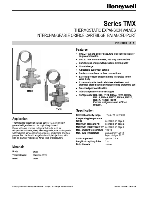
Series TMXTHERMOSTATIC EXPANSION VALVES INTERCHANGEABLE ORIFICE CARTRIDGE, BALANCED PORTPRODUCT DATAApplicationThermostatic expansion valves series TMX are used in general refrigeration and for original equipment.Plants with one or more refrigerant circuits such as refrigerated cabinets, deep freezing plants, milk cooling units, water chillers, air conditioning systems, cold stores and heat pumps. For plants with single and multiple injections, with high or low flow resistance, for all kind of distributors. MaterialsBody brassThermal head stainless steelBase brass Features•TMXL: TMX and solder base, two-way construction or angle construction•TMXB: TMX and flare base, two way construction •Damped gas charge with pressure limiting MOP •Liquid charge•Adjustable superheat setting•Solder connections or flare connections•External pressure equalisation is integrated in the valve body•Extreme durable due to stainless steel head and stainless steel diaphragm welded using protective gas •Balanced port construction•Interchangeable orifice cartridges•Refrigerants: R22, R23, R124, R134a, R227, R236fa,R401A, R404A, R407C, R410A, R422D,R507A,R508B,ISC89Furtherrefrigerants and MOP onrequest.SpecificationNominal capacity range 17.0 to 75.1 kW R22 Evaporating temperaturerange see table on page 2 Maximum pressure PS see table on page 2 Maximum test pressure PF see table on page 2Max. ambient temperature 100 °CMax. bulb temperature gas charge: 140 °Cliquid charge: 70 °CStatic superheat approx. 3.5 KLength of capillary tube 2 mBulb diameter 16 mmTMXBTMXLSERIES TMXThermal Charges and Temperature Ranges 1. Gas charge with pressure limiting MOPRefri-gerant EvaporationtemperaturerangeMOP PS(bar(a))PF(bar(a))Commercial refrigerantsR22 +15 °C to -45 °C MOP +15 °C 36 39.6 +10 °C to -45 °C MOP +10 °C 36 39.6±0 °C to -45 °C MOP ±0 °C 29 31.9-10 °C to -45 °C MOP -10 °C 29 31.9-18 °C to -45 °C MOP -18 °C 29 31.9 R134a +25 °C to -40 °C MOP +25 °C 34 37.4 +20 °C to -40 °C MOP +20 °C 34 37.4+15 °C to -40 °C MOP +15 °C 34 37.4+10 °C to -40 °C MOP +10 °C 34 37.4±0 °C to -40 °C MOP ±0 °C 29 31.9 R401A +10 °C to -40 °C MOP +10 °C 34 37.4 R404A +10 °C to -50 °C MOP +10 °C 36 39.6 ±0 °C to -50 °C MOP ±0 °C 36 39.6-10 °C to -50 °C MOP -10 °C 34 37.4-18 °C to -50 °C MOP -18 °C 34 37.4-30 °C to -50 °C MOP -30 °C 29 31.9 R407C +15 °C to -30 °C MOP +15 °C 36 39.6 +10 °C to -30 °C MOP +10 °C 36 39.6±0 °C to -30 °C MOP ±0 °C 29 31.9 R410A +15 °C to -50 °C MOP +15 °C 40 44.0 -10 °C to -50 °C MOP -10 °C 29 31.9-15 °C to -50 °C MOP -15 °C 29 31.9-20 °C to -50 °C MOP -20 °C 29 31.9 R422D +15 °C to -45 °C MOP +15 °C 36 39.6 -18 °C to -45 °C MOP -18 °C 29 31.9 R507A +10 °C to -50 °C MOP +10 °C 36 39.6 ±0 °C to -50 °C MOP ±0 °C 36 39.6-18 °C to -50 °C MOP -18 °C 34 37.4 Further refrigerants and MOP on request.Refri-gerantEvaporationtemperaturerangeMOP PS(bar(a))PF(bar(a)) Deep freeze refrigerantsR23 -40 °C to -80 °C MOP -40 °C 29 31.9 -55 °C to -80 °C MOP -55 °C 29 31.9 R410A -40 °C to -70 °C MOP -40 °C 29 31.9 R508B -55 °C to -100 °C MOP -55 °C 29 31.9 Isceon 89-40 °C to -70 °C MOP -40 °C 29 31.9 Further refrigerants and MOP on request.MOP valves protect the compressor by limiting the increase of suction pressure.The MOP value should be chosen for the max. permissible suction pressure of the compressor or min. 5 K higher than the required evaporating temperature of the system.For orders without any MOP indication a valve with MOP+ 10 °C will be delivered.With gas charged valves and MOP it is under all operating conditions necessary that the bulb is always colder than the capillary tube and the thermal head!With the Honeywell TMX series the thermal head is heated advantageously by the liquid refrigerant. The warm thermal head is on the safe side at any time.2. Liquid chargeRefrigerant Evaporationtemperature rangeR22 +30 °C to -45 °CR124 +50 °C to -10 °CR134a +20 °C to -40 °CR227 +40 °C to -10 °CR236fa +30 °C to -10 °CR404A +10 °C to -50 °CR407C +30 °C to -30 °CFurther refrigerants on request.CapacitiesNominal capacitiy (kW)*Type Orifice sizeR22 R134a R404A R407C R410A R422D R507A R124 R227 R236fa4.5 17.0 11.8 12.0 16.4 20.3 11.3 12.1 9.4 6.6 6.0 TMXL 4.7522.415.915.8 21.6 26.8 15.3 15.9 12.4 8.7 8.05 29.1 20.0 20.5 28.0 34.8 19.8 20.7 16.1 11.3 10.3 and6 42.4 27.6 29.8 40.8 50.8 28.9 30.1 23.5 16.4 15.17 54.5 35.3 38.3 52.5 65.3 37.1 38.7 30.2 21.1 19.4 TMXB 8 64.1 43.3 45.1 61.8 76.9 43.7 45.6 35.6 24.9 22.810 75.1 51.0 52.8 72.3 90.0 51.2 53.3 41.7 29.1 26.7 * Capacities are based on t0 = +4 °C, t c = +38 °C and 1 K subcooled liquid refrigerant entering the valve.For refrigerant R124, R227 and 236fa: Capacities are based on t0 = +10 °C, t c = +50 °C and 1 K subcooled liquidrefrigerant entering the valve.For other operating conditions see capacity charts in Honeywell catalogue or consult the Honeywell software.SERIES TMXD imensions and WeightsConnectionsTypeInlet (A) + (B)Outlet(C) + (D)PressureequaliserWeight(kg)TMX - - 7/16" UNF approx. 0.60XD ---approx.0.1412 + 16 mm ODF 16 + 22 mm ODF -XLStwo-way construction 1/2" + 5/8" ODF 5/8" + 7/8" ODF -approx. 0.4112 + 16 mm ODF 16 + 22 mm ODF -XLSangle construction 1/2" + 5/8" ODF 5/8" + 7/8" ODF -approx. 0.32XBStwo-way construction7/8" UNF 7/8" UNF - approx. 0.49SERIES TMXInstallation• The valves may be installed in any position.• The external pressure equaliser line should be 6 mm or 1/4” in diameter and is to be connected downstream of the remote bulb. An overbow is recommended in order to prevent the ingress of oil into the equaliser line. • The bulb should preferably be positioned on the upper half of a horizontal suction line but never after a liquid trap. As a general rule, bulbs of expansion valves should be insulated to prevent them being affected by the ambient temperature. • Do not bend or squeeze the bulb when tightening the bulb clamp • Never quench the base with water after soldering, this may cause cracks and distort the sealing surfaces. • The screws fixing the valve body to the solder base must be tightened in diagonal sequence (torque 20 Nm). • Constructive modifications at the valve are not allowed.Superheat AdjustmentIn general the Honeywell valves should be installed with the factory setting for the used refrigerant unaltered. This superheat adjustment is calibrated for lowestsuperheating and optimum evaporator utilisation. However, should it be necessary to adjust the superheat, turn the adjusting spindle as follows:Turning clockwise = reduced refrigerant mass flow, increase of superheat Turningcounterclockwise=increased refrigerant mass flow, decrease of superheatOne turn of adjusting spindle alters superheat setting by approx. 0.3 bar. Increase of superheat setting results in a lower MOP-value and vice versa.K A T -T M X -002Type Code / Order Information (Part Programme)1. Valve bodyAutomation and Control Solutions Honeywell GmbH Hardhofweg74821 Mosbach/Germany Phone: +49 (0) 62 61 / 81-475 Fax: +49 (0) 62 61 / 81-461E-Mail:*****************************Manufactured for and on behalf of the Environment and Combustion Controls Division of Honeywell Technologies Sàrl, 1180 Rolle, Z. A. La Pièce 16, Switzerlandby its authorized representative Honeywell GmbH。
高性能无油商业冷冻吸收设备用户手册说明书
High Performance Oilless CommercialRefrigerant Recovery UnitUser Manual2079-1130Rev. 6 – May 2010entirety. It is important that you have a thorough understanding of the procedures outlined in this manual. Failure to follow these procedures could void all manufacturer warranties.cylinder. Ensure that you are using the proper DOT recovery cylinder for the refrigerant that you are recovering. NOTE: R-410 is capable of pressures exceeding 600 psi. Typical DOT recovery cylinders are rated at 350 psi with a pressure relief set at 550 psi. These cylinders should not be used with R-410A. Only cylinders rated at 400 psi with the relief valve setting at 600 psi should be used to for R-410A. Failure to use the proper cylinder can be extremely dangerous!the refrigerant manufacturermay cause heart irregularities, unconsciousness, or death. Deliberate inhalation of refrigerants is extremely dangerous and may cause death. Vapor reduces the oxygen available for breathing and is heavier than air. Decomposition products are hazardous. Liquid contact can cause frostbite. All refrigerant containers, equipment, and hoses are under high pressure.•••••••and other vessels containing refrigerants should be handled at all times as if under high pressure.IEC 60320 type plug supplied power-cordrefrigerant level in the recovery cylinder in order to prevent overfilling.use with R-410A.approved for use with R-410A.3.4.Notecompressor. This indicates that too much liquid is entering the compressor. The inlet valve must be regulated (closed) until this knocking sound stops, otherwise compressor damage could occur. Pumping liquid when the compressor is knocking will damage the compressor, reduce the compressor life,and should not occur under normal recovery operations.5.6.refrigerant level in the recovery cylinder in order to prevent overfilling. use with R-410A.approved for use with R-410A.3.R-410A. Overfilling or over-pressurizing your recovery cylinder is extremely dangerous WHEN RECOVERING VAPOR:slowing down or by making a “knocking” sound, reduce the inlet pressure by closing or “throttling” the inlet valve until the STINGER begins to run normally.WHEN RECOVERING LIQUID:STINGER should be throttled back by slowly closing the inlet valve until the knocking noise stops. This action will prevent compressor damage.Ensure that you are using the proper DOT recovery cylinder for the refrigerant that you are recovering.Typical DOT recovery cylinders are rated at 350 psi with a pressure relief set at 550 psi. These cylinders should not be used with R-410A!pressure relief set at 600 psi should be used to recover R-410A. Failure to use the proper cylinder can be extremely dangerous.If your STINGER is equipped with the optional 80% tank full shutoff cord, connect this cord to a DOT recovery cylinder’s float switch. This cord connection will automatically shut OFF the STINGER when the recovery cylinder reaches 80% of its liquid-full limit. It is recommended that you use this cord for added safety.If your STINGER is not equipped with an 80% tank full shutoff cord, or if you are using a recovery cylinder that does not have a float switch,overfilling the cylinderNote:must be installed on the shutoff cord in order for the STINGER to operate.Bacharach uses and recommends the Air Conditioning & Refrigeration Institute's (ARI) Guideline K for the safe filling and handling of used refrigerant. This Publication is available。
液氮贮存输送系统使用说明书

液氮贮存输送系统使用维护说明书二○○八年六月目录第一章概述第二章各部机的主要性能参数第三章成套设备的安装第四章成套设备的使用及停车操作第一章概述液氮气化系统系统设备,是用来气化空分设备提取的液氮,并将其升压、蒸发成气态氮设备。
一、主要技术数据1、输送氮气的流量18600m3/h200m3/h200m3/h2、输送压力8.2Mpa 0.7Mpa 15Mpa3、电耗量: 175KW 11KW 5.5KW二、成套装置的组成进口充槽车液氮泵1台进口高压液氮泵1台充瓶液氮泵1台空温式气化器1台QDZ22气化器1台1903DCK充瓶装置1套CF200A低温液体贮槽1台ZN133直属件、阀门1套三、工艺流程简述(见流程图)空分设备生产的液氮通过液氮泵01P801升压至8.2 MPa后进入水浴式气化器(01E801),迅速被气化器的水(温度+60℃)蒸发成气态氮,水是用蒸汽加热的,气化后的氮气去用户。
另一路通过液氮泵01P805升压至15.0Mpa后进入空浴式气化器,气化后的氮气去充瓶装置。
第二章各部机的主要性能参数一、液氮泵(01P801) 变频迷宫密封电机型号:进口件电机功率175KW出口压力8.2MPa输送流量18600 m3/h详见该机说明书二、气化器形式空温式输送流量200m3/h出口压力15.0MPa输出温度:不低于环境温度-8℃详见该机使用说明书。
三、液氮泵(01P805) 充瓶泵电机型号:输送流量200m3/h出口压力15.0MPa电机功率 5.5KW四、液氮泵(01P802) 槽车泵进口电机型号:输送流量200L/MIN出口压力0.7MPa电机功率11KW详见该说明书。
五、水浴蒸发器形式水浴式输送气氮流量22000m3/h输送压力8.2MPa输出温度: 15℃蒸汽耗量:约6000KG/H 详见该机使用说明书。
六、低温液氮贮槽型式珠光砂粉末真空贮槽几何容积200m3设计压力0.2Mpa最高工作压力0.25MPa贮存介质液氮详见该机使用说明书。
RevcoTM RDE 系列、 FormaTM FDE 系列、 HERAfreezeTM HDE 系

超低温降温仪 Revco TM RDE 系列、Forma TM FDE 系列、HERAfreeze TM HDE 系列和 Thermo Scientific TM TDE 系列安装和操作329712H61 •修订版 F • 2022 年 3 月重要请阅读本说明手册。
不按照本手册中的说明操作可能会导致设备损坏、操作人员受伤和设备性能低下。
小心所有内部调整和维护均必须由合格的检修人员执行。
本手册中的材料仅供参考。
其中的内容和产品可能发生更改,恕不另行通知。
赛默飞世尔科技不提供任何关于本手册的声明或担保。
在任何情况下,Thermo 对因使用本手册或与使用本手册相关的直接或间接损坏不负任何责任。
© 2022 Thermo Fisher Scientific Inc. 保留所有权利。
目录型号 (1)安全注意事项 (2)开箱 (3)装箱单 (3)一般性建议 (4)温度监测 (4)一般用法 (4)初次装载 (4)电池舱门打开/关闭 (4)运行标准 (5)电气规格 (5)安装 (6)位置 (6)保护导体电流 (6)调平 (6)刮冰刀 (6)备份系统(可选) (7)超级绝缘机柜结构 (7)门操作 (7)压力均衡口 (7)安装远程警报连接器 (7)预期用途 (8)操作 (9)初始启动 (9)操作概述 (9)显示 (9)设置 (10)关机 (10)刮冰刀说明 (11)预期用途 (11)非预期用途 (11)注意事项和使用方法 (11)备份系统(可选) (12)CO2和 LN2注意事项 (12)安装 (12)启动 (13)操作 (13)温度记录仪(可选) (14)设置和操作 (14)更换记录纸 (14)校准调整 (14)维护 (15)清洁冷凝器 (15)清洁冷凝器过滤器 (15)垫圈维护 (15)为降温仪除霜 (15)电池维护 (15)维护计划 (16)故障排除指南 (17)错误代码 (20)保修 (21)保修(国际) (22)附录 A:警报摘要 (23)附录 B:Modbus ASCII 参数表 (25)WEEE 合规 (34)联系信息 (35)型号表 1. 适用的型号Forma - FDExxx86F*300/400/500/600A/D/VForma - FDExxx86F* - ULTS 300/400/500/600A/D/VThermo Scientific –TDExxx86F*300/400/500/600A/D/VThermo Scientific –TDExxx86F*- ULTS300/400/500/600A/D/VHERAfreeze – HDExxx86F*300/400/500/600A/D/VRevco - RDExxx86F*300/400/500/600A/D/V1|型号Thermo Fisher Scientific 超低温降温仪安全注意事项在本手册中,使用下列符号和惯例:下面列举了一些适用于本产品的重要安全防范措施:EMC(适用时)此设备的 EMC 注册仅限商业用途。
液氮最终系统操作手册2013.10.6

液氮汽化站自控系统操作手册一、引言本手册是中石油唐山LNG项目中液氮气化站自控系统操作手册,编写手册目的是方便操作人员了解该系统的功能并可操作该设备。
二、系统操作说明。
1、基本操作说明当控制柜由断电转为供电时,触摸屛将自动开启进入系统界面。
如图1所示。
图1 开机画面触碰后进入目录界面,如图2所示。
通过目录可以分别进入监控界面、项目介绍和系统设定界面。
图2 目录界面系统设定功能,当发现触摸屏触摸位置存在偏差时,可点击校准来校准触摸屛,按照触摸屏来重新校准,保证触摸的位置精准度。
图3 系统设定界面监控界面可以看到整个流程简图,包含各温度点、阀门、各设备状态及相关报警情况。
如图4所示。
可点击最小排按钮进行画面切换。
图4 监控界面阀门颜色出现绿色,表示打开状态,例如;出现红色,表示关闭状态,例如。
电加热器出现绿色时,表示打开状态,例如;出现红色,表示关闭状态,例如。
温度、压力显示出现红黑闪烁时,说明出现报警,可查看下方报警列表或者报警画面中看到详细的报警内容。
如图5所示。
图5报警提示可以通过界面下部的界面切换按钮浏览电加热器界面、报警画面和参数设置画面。
也可回到首页。
参数设置需要进入密码,用户名及密码均为“123”,登陆权限只保留1分钟。
2、汽化器部分操作2.1 阀门基本操作点击“XV101A按钮”,可以打开阀门控制界面。
再点击“XV101A按钮”可以关闭该界面。
XV101B也同上。
绿色按钮表示可以点击,灰色按钮点击无效。
可以通过“转自动/手动”按钮切换该阀门的手自动状态。
手动状态时,可以点击“手动开/关”按钮打开和关闭该阀门(图6),不受自控程序影响。
自动状态时,可以点击“软启动/停止”按钮打开和关闭阀门(图7),但阀门将受自控程序影响自动更改状态,具体互锁逻辑见后。
并且,阀门自动状态时,阀门下方会出现“互锁”两字(图8),表示该阀门处于自动状态。
图6 手动状态图7 自动状态图8 自动状态2.2 汽化器启动操作打开管路上相应手动阀门,需要使用汽化器E2801A(E2801B)时,将XV101A(XV101B)转变为自动状态,点击“软启动”按钮,阀门将自动开启,并开启电加热器部分阀门、设备(如果这些设备处于自动状态下)。
液氮生物容器操作说明书

操作说明书Operations ManualLiquid Nitrogen Biological Container液氮生物容器2022.7版北京兰杰柯科技有限公司地址:北京市顺义区空港工业园区B区裕民大街9号电话:400-600-4213网址: 邮箱:***************目 录contents前 言开 箱 检 查第一章 产品说明1. 产品简介2. 产品部分名词术语3. 产品型号编制方法4. 产品静态液氮保存期的测试、计算方法第二章 产品结构1. 产品结构示意图2. 产品主要结构及其特点第三章 技术参数第四章 产品使用须知第五章 售后服务第六章 装箱清单1 1 2 2 2 3 3 4 4 4 5 6 8 9术语几何容积口径外径高度空重静态液氮保存期产品寿命定义由内胆内缘几何尺寸(不含颈管)所限定的空间体积。
颈管的内直径。
产品外壳筒体不含筋的外直径。
产品外形不含盖塞和提筒沿筒体轴向的最大长度。
产品在内胆为室温空气,带盖塞,不放提筒时的质量。
产品注入液氮预冷,不放提筒达到热平衡后,再盛满液氮静态放置全部挥发完的天数。
从产品出厂使用至液氮保存期低于出厂指标40%的时间间隔。
感谢购买液氮生物容器。
本用户手册包含了仪器的功能和操作过程等,为了确保正确使用仪器,在操作仪器前请仔细阅读本手册。
请妥善保存手册,以便碰到问题时快速阅读和解决。
用户收到产品时应及时打开仪器包装箱,对照装箱清单检查仪器和配件,若发现仪器或配件包装错误、数量不对、包装或产品破损等情况,请在7天内及时与销售商或生产商联系,超过此时间将不予按照非产品质量问题处理原则处理。
前 言开 箱 检 查第 一 章 产品说明1. 产品简介2. 产品部分名词术语液氮生物容器是生物样本储存的主要设备,它科学地解决了液氮贮存时容器由于热对流、传导和辐射引起的液氮大量蒸发损失的难题。
随着科学技术的发展和人类社会的进步,高真空多层绝热技术及其新材料、新工艺被采用,使液氮容器具备了优良的绝热性能,可将其保存的液氮(-196℃)的自然蒸发损失降到更低,因此,液氮容器产品被广泛运用在畜牧业、医疗及科研、机械加工等领域。
超精确冷却器:超精确冷却器用户指南说明书
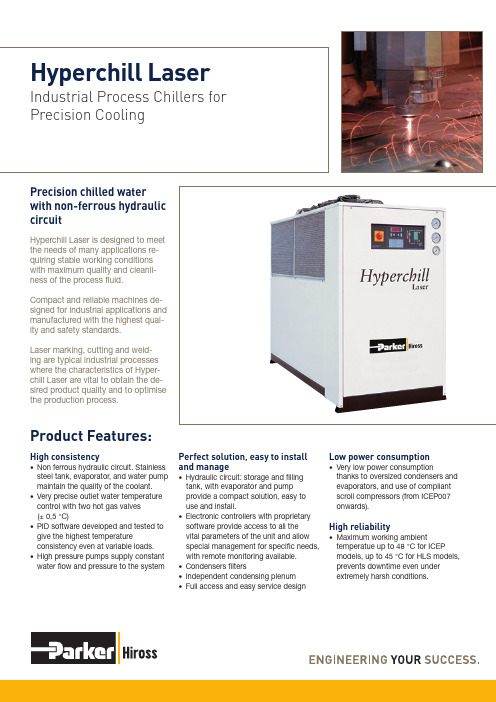
High consistency• Non ferrous hydraulic circuit. Stainless steel tank, evaporator, and water pump maintain the quality of the coolant.• Very precise outlet water temperature control with two hot gas valves (± 0,5 °C)• PID software developed and tested to give the highest temperatureconsistency even at variable loads.• High pressure pumps supply constant water flow and pressure to the systemPerfect solution, easy to install and manage• Hydraulic circuit: storage and filling tank, with evaporator and pump provide a compact solution, easy to use and install.• Electronic controllers with proprietary software provide access to all the vital parameters of the unit and allow special management for specific needs, with remote monitoring available.• Condensers filters• Independent condensing plenum • Full access and easy service designHyperchill LaserIndustrial Process Chillers for Precision CoolingPrecision chilled water with non-ferrous hydraulic circuitHyperchill Laser is designed to meet the needs of many applications re-quiring stable working conditions with maximum quality and cleanli-ness of the process fluid.Compact and reliable machines de-signed for industrial applications and manufactured with the highest qual-ity and safety standards.Laser marking, cutting and weld-ing are typical industrial processes where the characteristics of Hyper-chill Laser are vital to obtain the de-sired product quality and to optimisethe production process.Low power consumption• Very low power consumptionthanks to oversized condensers and evaporators, and use of compliant scroll compressors (from ICEP007 onwards).High reliability• Maximum working ambienttemperatue up to 48 °C for ICEP models, up to 45 °C for HLS models, prevents downtime even under extremely harsh conditions.Product Features:Microprocessors: allow complete control of the unit parameters. Proprietary software from ICEP007 onwards allows and wide range of programming and remote monitoring options.Compliant scroll compressors: (from ICEP007 onwards) with less moving parts and compliant technology provide excellent efficiency, high reliability, and very low noise levels.Water and refrigerantmanometers permit easy control of the working conditions.Stainless steel plateevaporators, compact and efficient, external to the tank.Water tank: generouslydimensioned guarantee high reliability and improved temperature control.Differential pressure switch: protects pump and evaporator in case of flow shut down.Mesh filters: (from ICEP007 onwards) condenser protection from dirt and contamination, reduces maintenance costs and the risk of downtime.Water pump: available with different head pressures to fit the end user application, can be also configured as twin system for redundancy.MODBUS interface fitted on ICEP models (from ICEP007); optionalfor HLS modelsThe performance of high-powered lasers depends on effective cool-ing. High-powered lasers generate a significant amount of heat that must b e removed from the laser system to avoid overheating critical Versions:• Low ambient temperature (from ICEP007 onwards): additional condensing control for continuous operation in cold ambients (nega-tive temperature). Available for air cooled versions with axial fans.Options:• Water by-pass: externally adjust-able allowing the correct flow throught the system to be set.• Flow switch: to be used as an alarm signal in case of water flow shut down.components. Carbon dioxide (CO 2) lasers, excimer lasers, ion lasers, solid-state lasers, and dye lasers all use liquid cooling to remove excess heat. Laser liquid cooling can help accomplish three goals: maintain-• Precision control: when very precise water temperature is re-quired (± 0,5 °C).• Special and multiple pumps: higher (P50-5bar) or lower (P15-1,5bar) head pressure available to suit different hydraulic cir-• Check valves: external non-return valve + solenoid valve to separate the hydraulic circuit when the unit is switched off.• Wheels (ICEP002-ICEP014): for easy of transport.ing a precise laser wavelength and higher output efficiency, achieving desired b eam quality, and reduc-ing thermal stress on a laser sys-tem.cuits. Double stand- by pump for higher reliability.• Antifeeze heating (from ICEP007 onwards): avoids freezing when the unit is switched off. Can also be used as a heater to warm up the system.• Remote control kits: base version for remote ON/OFF and general alarm monitoring or advanced version for complete unit manage-ment via remote monitoring.• Water filters for circuit cleanli-ness and machinery protection.Technical dataTo obtain the required cooling capacity multiply the value at nominal conditions by the above correction factors (i.e. cooling capacity = Pxf1xf2xf3, where P is the cooling capacity at conditions (1). Hyperchill Laser, in its standard configuration, can operate up to ambient temperatures of max 48 °C for ICEP models, 45 °C for HLS models and min 5 °C and water temperatures of max 30 °C inlet and min. 0 °C outlet. The above correction factors are approximative: for a precise selection always refer to the software selection program.(1) at water inlet/outlet temperature = 20/15 °C, glycol 0 %, ambient temperature 25 °C. (2) at water inlet/outlet temperature = 25/20 °C, glycol 0 %, ambient temperature 35 °C.(3) referred to free field conditions at a distance of 10m from unit, measured on condenser side, 1 m from ground.ICEP002ICEP003-005ICEP007-060HLS076-116As the manufacturer of process chillers delivering water at a design temperature of 15 °C, Parker Hannifin Manufacturing s.r .l., Gas Separation and Filtration Division EMEA, declares that Parker chillers are exempt from Ecodesign EU regulation 2016/2281.Correction factorsBULHLS-04-ENYour local authorized Parker distributor© 2018 Parker Hannifin Corporation. All rights reserved.Europe, Middle East, AfricaAE – United Arab Emirates, DubaiTel: +971 4 8127100 ********************AT – Austria, Wiener Neustadt Tel: +43 (0)2622 23501-0 *************************AT – Eastern Europe, Wiener NeustadtTel: +43 (0)2622 23501 900 ****************************AZ – Azerbaijan, Baku Tel: +994 50 2233 458****************************BE/LU – Belgium, Nivelles Tel: +32 (0)67 280 900*************************BG – Bulgaria, Sofia Tel: +359 2 980 1344**************************BY – Belarus, Minsk Tel: +48 (0)22 573 24 00 ************************CH – Switzerland, Etoy Tel: +41 (0)21 821 87 00*****************************CZ – Czech Republic, Klecany Tel: +420 284 083 111*******************************DE – Germany, Kaarst Tel: +49 (0)2131 4016 0*************************DK – Denmark, Ballerup Tel: +45 43 56 04 00*************************ES – Spain, Madrid Tel: +34 902 330 001 ***********************FI – Finland, Vantaa Tel: +358 (0)20 753 2500 *************************FR – France, Contamine s/Arve Tel: +33 (0)4 50 25 80 25 ************************GR – Greece, Piraeus Tel: +30 210 933 6450 ************************HU – Hungary, Budaörs Tel: +36 23 885 470*************************IE – Ireland, Dublin Tel: +353 (0)1 466 6370 *************************IL – IsraelTel: +39 02 45 19 21************************IT – Italy, Corsico (MI) Tel: +39 02 45 19 21 ***********************KZ – Kazakhstan, Almaty Tel: +7 7273 561 000****************************NL – The Netherlands, Oldenzaal Tel: +31 (0)541 585 000 ********************NO – Norway, Asker Tel: +47 66 75 34 00************************PL – Poland, Warsaw Tel: +48 (0)22 573 24 00 ************************PT – PortugalTel: +351 22 999 7360**************************RO – Romania, Bucharest Tel: +40 21 252 1382*************************RU – Russia, Moscow Tel: +7 495 645-2156************************SE – Sweden, Spånga Tel: +46 (0)8 59 79 50 00 ************************SK – Slovakia, Banská Bystrica Tel: +421 484 162 252**************************SL – Slovenia, Novo Mesto Tel: +386 7 337 6650**************************TR – Turkey, Istanbul Tel: +90 216 4997081 ************************UA – Ukraine, Kiev Tel: +48 (0)22 573 24 00 ************************Parker WorldwideUK – United Kingdom, Warwick Tel: +44 (0)1926 317 878 ********************ZA – South Africa, Kempton Park Tel: +27 (0)11 961 0700*****************************North AmericaCA – Canada, Milton, Ontario Tel: +1 905 693 3000US – USA, Cleveland Tel: +1 216 896 3000Asia PacificAU – Australia, Castle Hill Tel: +61 (0)2-9634 7777CN – China, Shanghai Tel: +86 21 2899 5000HK – Hong Kong Tel: +852 2428 8008IN – India, MumbaiTel: +91 22 6513 7081-85JP – Japan, Tokyo Tel: +81 (0)3 6408 3901KR – South Korea, Seoul Tel: +82 2 559 0400MY – Malaysia, Shah Alam Tel: +60 3 7849 0800NZ – New Zealand, Mt Wellington Tel: +64 9 574 1744SG – Singapore Tel: +65 6887 6300TH – Thailand, Bangkok Tel: +662 186 7000TW – Taiwan, Taipei Tel: +886 2 2298 8987South AmericaAR – Argentina, Buenos Aires Tel: +54 3327 44 4129BR – Brazil, Sao Jose dos Campos Tel: +55 800 727 5374 CL – Chile, Santiago Tel: +56 2 623 1216MX – Mexico, Toluca Tel: +52 72 2275 4200EMEA Product Information Centre Free phone: 00 800 27 27 5374(from AT , BE, CH, CZ, DE, DK, EE, ES, FI, FR, IE, IL, IS, IT , LU, MT , NL, NO, PL, PT , RU, SE, SK, UK, ZA) US Product Information Centre Toll-free number: 1-800-27 27 537/gsfe。
- 1、下载文档前请自行甄别文档内容的完整性,平台不提供额外的编辑、内容补充、找答案等附加服务。
- 2、"仅部分预览"的文档,不可在线预览部分如存在完整性等问题,可反馈申请退款(可完整预览的文档不适用该条件!)。
- 3、如文档侵犯您的权益,请联系客服反馈,我们会尽快为您处理(人工客服工作时间:9:00-18:30)。
ISO 9001 (Bureau Veritas); ISO 38342 Nederlands Instituut voor Lastechniek (NIL); PED H/ H1 (Lloyd`s register); VCA** (Bureau Veritas);
北京宇丰凯电子有限公司
VIP-Lines 详细参数: 真空隔离绝热管道规格
Pipe size Process line Vacuum
Max.Capacity
Heat in leak
Weight kg/m
DN10 DN15 DN20 DN25
1" 1½" 2" 2½" 3" 4" 6" 介质
(mm)
jacket (mm) indication(L/h) indication(W/m)
EN, AD200 16 bar(g) Johnston Bayonet/Unions After retention test(std.24 hr) less than 2×10⁻⁴ mbar Process clean(suitable for Oxygen use)
1.4301/1.4541/1.4571 1.4541/1.4571 1.4301 1.4301/1.4306/1.4307 Glass and aluminium foil25 layers Standard Buna N
60000
3.3
26.5
2K (-271°C) to 195K (-78°C) such as He, H2, N2, Ar, O2, Kr, Xe and LNG.
北京宇丰凯电子有限公司
Design conditions
Design:
According to PED
DeMaCo 的真空隔离绝热软管是专门用于极端温度液体的柔性传输系统,最通常的应用 是用于低温液化气的传输。
真空隔离绝热软管的内部和外部都是由不锈钢软管制成,用于传输低温液化气,中间是 真空夹层。内外软管由不锈钢线编织,可以提高强度和耐用性。
夹层材料由玻璃布和玻璃丝制成,可以确保内部软管固定在整个管线的中心。分子筛的 配备可以吸收分子保持恒定的真空度。在内部软管的表面缠有 25 层玻璃-铝箔,可以使热辐 射最小化。
Retention test:
24 hours
Optional Testing
Cold shock testing
Extended retention test
Additional pressure test
Additional NDE
北京宇丰凯电子有限公司
真空隔离绝热软管(VI flexible - Vacuum Insulated Flexible)
DeMaCo standard 1000 cycles at 100% stroke
Vacuum Level:
After retention test(std.24 hr) less than 2×10⁻⁴ mbar
Cleanliness process pipe: Process clean(suitable for Oxygen use)
NDE:
According to PED / design code
Helium leak test:
All spools with leak rate less than 1x10⁻⁹ mbar l/sec
Vacuum test:
Prior to retention test less than 1x10⁻⁵ mbar
液氮冷却系统示意图
液氮罐或制
氮设备
真空绝热输液管道
用
状态分离 真空绝热输液软管
氮
器
设
真空绝热回气软管
备
气态液氮输
送管道
大
气
北京宇丰凯电子有限公司
真空隔离绝热管道(VIP-Vacuum Insulated Pipeline)
DeMaCo 的 VIP-Lines 真空隔离绝热管道主要由内外两层管道构成,内层的不锈钢管道 传输液态气体,外层的不锈钢管道形成真空隔离管套。特殊的内部构造设计使其具有极低的 热传导率,同时保证内层管道准确地固定在外层管套的中心。层间分子吸收材料保证管道间 的高真空条件,内管采用 25 层玻璃/铝箔包围防护,可最大限度防止热辐射影响。内部波纹 管设计可补偿“热胀冷缩”造成的尺寸变化。
现在,DeMaCo 早已成为全球同行业中的佼佼者,在全球占有较大的市场份额,其客户 群体分布在世界各大洲和主要国家,涵盖多个领域,从大型的系统工程到每一个微小部件, DeMaCo 都力求完美地为客户寻求最佳解决方案,其完美的产品品质和完善的服务体系为用 户提供了坚实的保障。其产品应用包括航空航天领域、电子领域、汽车制造领域、冶金领域、 石化领域、医药领域、生物领域、食品领域等多种关系到国计民生和高尖端科技领域。 DeMaCo 先后获得了世界多个认证体系的质量认证证书,已成为用户心目中代表高品质产品 的标准。
液氮冷却系统概述
对于超高真空半导体设备(例如分子束外延 (MBE)系统)是工艺很复杂的系统,它需要运 行在超高真空环境下。系统的冷屏需要液氮来冷 却,冷屏的容积要足够大,这有助于提高真空的 泵取速度并在真空腔室内达到更好的真空水平。 做为欧洲最大的低温工艺制造商之一 DeMaCo 可 以向用户提供标准组件的用于相关系统的液氮供给系统。液氮供给系统的特别设计可以使 用户的生产能力最优化,液氮的供应完全自动化。
2011
DeMaCo 液氮冷却系统
中国总代理: 北京宇丰凯电子有限公司 2011‐3‐22
北京宇丰凯电子有限公司
DeMaCo 公司简介
荷兰 DeMaCo 公司是一家专门从事冷却系统的设计、制造和服务的国际知名公司,已 有近半个世纪的历史。DeMaCo 从创立的伊始就专心致力于各种冷却系统的研究和生产,无 论是从工程解决方案,还是其产品的设计、制造,都形成了自己独特的风格,其独到的见解, 优秀的产品质量,高效的服务在全球范围内受到了广大用户的青睐,为 DeMaCo 赢得了国 际声誉。
北京宇丰凯电子有限公司
真空绝热状态分离器(Vacuum Insulated Phase separator)
状态分离器的首要作用是从液氮中分离 出气氮。状态分离器还有一个作用就是将液 氮罐的液氮压力降低到使用压力。同时状态 分离器可以避免由于压力骤降而造成的液氮 突然断流现象,状态分离器的分级存储功能 能够消除液氮罐输出流量波动起伏带来的不 良影响。
真空隔离绝热软管规格
Pipe size
Dimensioni ng process OD (mm)
Vacuum OD(mm)
Bend radius(mm)
Capacity
Weight
Heat in leak
Indication(L/h) (kg/h) indication(W/m)
DN10
Ø12
Ø44
液氮冷却系统组成
一个液氮供应系统由如下部分组成:从液氮存储罐到 真空状态分离器之间,真空绝热良好的输液管路;用于分 离气氮和液氮的状态分离器;一个或多个真空绝热软管 (数量取决于冷屏和分接点的数量)与状态分离器相连; 液氮从状态分离器经软管供应给半导体设备系统的冷屏 和分接点,从冷屏出来的气氮再通过软管返回到状态分离 器; 然后通过一个真空管路将气体排放到空气中。
4500
0.85
6.5
Ø60.3x1.6 Ø114.3x2.0
6000
1.0
8.4
Ø76.1x2.0 Ø139.7x2.0
11500
1.3
8.7
Ø88.9x2.0 Ø154x2.0
16000
1.9
11.5
Ø114.3x2.0 Ø168.3x3.0
27000
2.0
17.4
Ø168.3x2.0 Ø219.1x3.0
Ø12x1.0
Ø63.5x1.5
300
0.40
2.7
Ø18x1.O
Ø63.5x1.5
500
0.45
2.9
Ø23x1.5
Ø63.5x1.5
1000
0.55
3.2
Ø28x1.0
Ø63.5x1.5
2000
0.65
3.1
Ø33.7x1.6 Ø76.1x2.0
3000
0.75
4.1
Ø48.3x1.6 Ø88.9x2.0
All spools According to PED / design code According to PED / design code All spools with leak rate less than 1x10⁻⁹ mbar l/sec Prior to retention test less than 1x10⁻⁵ mbar 24 hours
340
0-175
2.2
1.1
DN10
Ø12
Ø66
440
0-175
3
1.0
DN15
Ø15
Ø66
440
100-300
4
1.2
DN25
Ø25
Ø66
440
600-1200
4.4
1.6
1"
Ø32
Ø84
550
1200-1800
5.3
1.7
1½"
Ø50
Ø101
650
1800-2600
6.1
1.9
2"
Ø65
Ø127
Design codes:
EN or AD200