TI公司---422和485标准概述和系统结构cn
(完整word版)RS485,RS422设计指南

前言 01 RS-485与RS-422性能指标及其标准 02 RS-485与RS-422器件及材料说明 (1)3 RS-485与RS-422设计原理 (1)3.1 基本原理 (1)3.1.1RS-485与RS -232电路的区别与优势 (1)3.1.2长短连接的判断标准、物理表现与应对措施 (3)3.1.3 RS-485与RS-422典型应用电路与选择方法 (4)3.1.4 485总线上处理竞争的方法 (7)3.2 可靠性的设计 (8)3.2.1 网络配置 (8)3.2.2 总线匹配 (8)3.2.3 引出线 (10)3.2.4 失效保护 (10)3.2.5 地线与接地 (11)3.2.5.1 共模干扰问题 (11)3.2.5.2 电磁辐射(EMI)问题: (12)3.2.6 瞬态保护 (13)3.2.7 其它需要注意的问题 (14)3.3 电源和接地 (14)4 维护说明 (14)参考资料 (15)RS485、RS422接口设计指南前言RS-485标准最初由电子工业协会(EIA)于1983年制订并发布,后由TIA-通讯工业协会修订后命名为TIA/EIA-485-A,习惯地称之为RS-485。
RS-485由RS-422发展而来,而RS-422是为弥补RS-232之不足而提出的。
为改进RS-232通信距离短、速率低的缺点,RS-422定义了一种平衡通信接口,将传输速率提高到10Mbps,传输距离延长到4000英尺(速率低于100kbps时),并允许在一条平衡线上连接最多10个接收器。
RS-422是一种单机发送、多机接收的单向、平衡传输规范,为扩展应用范围,随后又为其增加了多点、双向通信能力,即允许多个发送器连接到同一条总线上,同时增加了发送器的驱动能力和冲突保护特性,扩展了总线共模范围,这就是后来的EIA RS-485标准。
RS-485是一个电气接口规范,它只规定了平衡驱动器和接收器的电特性,而没有规定接插件、传输电缆和通信协议。
RS-422 和 RS485 标准概述与系统配置_英文
Application ReportSLLA070D–June2002–Revised May2010 RS-422and RS-485Standards Overview and SystemConfigurationsManny Soltero,Jing Zhang,and Chris Cockril HPA-Industrial Interface Updated by Kevin Zhang,Clark Kinnaird,and Thomas KugelstadtABSTRACTANSI TIA/EIA-422and TIA/EIA-485standards,commonly known as RS-422and RS-485,respectively, specify balanced data-transmission schemes for transmitting data over long distances in noisy environments.These standards are compared,and their basic differences and similarities are discussed.Techniques for impedance matching to minimize line reflections in several applications are presented,with laboratory test results.Contents1Introduction (3)2Overview of RS-422and RS-485Standards (3)2.1Selected RS-422Electrical Specifications (3)2.2Selected RS-485Electrical Specifications (9)3Failsafe Operation (12)3.1The Need for Failsafe Protection (12)3.2Internal Failsafe (13)3.3External Failsafe (13)4Suggested Termination and Grounding Techniques (13)4.1No Termination (13)4.2Parallel Termination (14)4.3AC Termination (16)4.4Multipoint Termination (17)4.5Ground Connections (18)5Typical System Configurations (21)5.1Daisy-Chain Configuration (21)5.2Bus and Stub Configuration (21)5.3Point-to-Point Configuration (22)6Summary Comparison of the Standards (22)6.1Common-Mode Range (22)6.2Line Contention (23)6.3Drive Current (23)7Conclusion (23)8Glossary (24)9Acknowledgment (24)10References (24)List of Figures1RS-422Balanced-Voltage Digital-Interface Circuit (4)2RS-422Open-Circuit Test Circuit (4)3RS-422Output-Voltage Test Circuit (5)4RS-422Short-Circuit Output-Current Test Circuit (5)5RS-422Power-Off Output-Current Test Circuit (5)6RS-422Test Circuit and Output-Signal Waveform (6) 7RS-422Input Receiver Test Circuit and I/V Plot (7)8RS-422Input-Sensitivity Test Circuit and Resultant Waveform (8)9RS-485Balanced-Voltage Digital-Interface Circuit (9)10RS-485U.L.Test Circuit and I/V Relationship (10)11RS-485Open-Circuit Test Circuit (10)12RS-485Output-Voltage Test Circuit (11)13RS-485Output-Voltage Test Circuit With Common-Mode Loading (11)14RS-485Short-Circuit Output-Current Test Circuit (11)15RS-485Output-Signal Test Circuit (12)16Differential Unterminated Configuration (13)17Differential Unterminated-Driver Output Waveforms (14)18Differential Unterminated-Receiver Input Waveforms (14)19Differential Parallel-Terminated Configuration (15)20Differential Parallel-Terminated Driver Output Waveforms (15)21Differential Parallel-Terminated Receiver Input Waveforms (16)22Differential AC-Terminated Configuration (16)23Differential AC-Terminated Driver Output Waveforms (17)24Differential AC-Terminated Receiver Input Waveforms (17)25Differential Multipoint-Terminated Configuration (18)26Grounding Configuration with Isolated Local Ground and PE (19)27Grounding Configuration with Connected Local Ground and PE (19)28Isolated Configuration (20)29Daisy-Chain Connection (21)30Stub Cables Connected to the Main Backbone (22)31Point-to-Point Connection (22)List of Tables1Input Sensitivity and Resultant Voltages of422-Compliant Devices (8)2Input Sensitivity and Resultant Voltages of485-Compliant Devices (12)3Summary of Termination Techniques (18)4Summary Comparison of RS-485and RS-422Specifications (23) Introduction 1IntroductionThe RS-422and RS-485standards,as they are known today,are balanced data-transmission schemes that offer robust solutions for transmitting data over long distances and noisy environments.The official titles for these two standards are ANSI TIA/EIA-422and TIA/EIA-485,respectively,and are revisedperiodically by the TR-30.2DTE-DCE Interfaces and Protocols Subcommittee to the Telecommunications Industry Association(TIA)TR-30Data Transmission Systems and Equipment Committee.Foridentification,RS-422and RS-485suffice.This application report offers an overview of the RS-422and RS-485standards.While many specifications are described in the official ANSI documents,only the most prevalent are discussed in this applicationreport.The purpose of this application report is to not duplicate the official documents,but to outline basic differences and similarities between the RS-422and RS-485standards.Major specifications are described in detail and the two standards are compared.Because impedance matching is an important aspect of differential data transmission in minimizing line reflections due to transmission-line effects,techniques for terminating different system applications are presented.Also,typical system configurations are taken into consideration for optimal application performance and cost constraints.2Overview of RS-422and RS-485StandardsOfficially,the RS-422standard's title is Electrical Characteristics of Balanced Voltage Digital InterfaceCircuits,and is published by the ANSI Telecommunication Industry Association/Electronic IndustriesAssociation(TIA/EIA).In the industry,the term RS-422is commonly used rather than the official name, and this document does the same.RS-422is specified as a simplex multidrop standard,which meansonly one driver and up to ten receivers can be attached to a bus.The RS-485standard's title is Electrical Characteristics of Generators and Receivers for Use in Balanced Digital Multipoint Systems.RS-485is commonly used,rather than its official title.If more than one driver is required,devices conforming to RS-485are recommended.RS-485specifications allow only one driver to send data at a time,and up to32unit loads(U.L.)can be placed on the bus.The U.L.concept isdescribed in this application report in the Selected RS-485Electrical Specifications section.RS-422and RS-485initially might appear to be similar,but are distinct,and interchangeability isdetermined by the bus architecture.The RS-485standard is written to be electrically compatible withRS-422.To illustrate their basic differences,a condensed description of each standard is presented in the following subsections.2.1Selected RS-422Electrical SpecificationsThe balanced-voltage digital interface is shown in Figure1.The driver(or generator)is labeled D,thereceiver is labeled R,and the termination impedance is ZT .The termination impedance should be equal tothe characteristic impedance of the cable,Zo ,and is used only once at the end of the cable.Becausematching termination impedance to Zo often is difficult to achieve and is application dependent,typically,±20%is sufficient.Also,up to nine additional receivers can be placed along the cable from points A and B to points A'and B',respectively.No restriction on maximum cable length is imposed by the RS-422 standard.Taking this into account,systems of up to1km are not uncommon,with signaling rates no higher than about100kbps.Speed and cable lengths work against each other.In other words,the longer the cable,the slower the signaling rate must be,while data can be transmitted faster on shorter cables.As a rule of thumb,the data signaling rate(in bps)multiplied by the cable length(in meters)should not exceed108.For example,a system with a cable measuring500m should not transmit data at speeds greater than200kbps(108/500).Logic (1 or 0)S0450-01Logic (1 or 0)V OAOverview of RS-422and RS-485StandardsA D =driver (or generator)B R =receiverCZ T =termination impedanceFigure 1.RS-422Balanced-Voltage Digital-Interface CircuitAlthough the input electrical characteristics of the RS-422-compliant receiver are identical to those of the RS-423-compliant receiver (ANSI TIA/EIA-423standard),the RS-423specifies an unbalanced signaling scheme,which is not within the scope of this application report.Descriptions of selected specified parameters are presented in the following paragraphs.2.1.1Open-Circuit Output Voltage (V OD ,V OA ,and V OB Measured)The output voltage shall not exceed ±6V under unloaded conditions,and the differential voltage[measured as the difference between an output voltage,V OA (V OB ),and its complementary output voltage,V OB (V OA )]is no greater than ±10V.See Figure 2for the test circuit.A |V OD |≤10V,|V OA |≤6V,and |V OB |≤6V B V OA =voltage on A outputC V OB =voltage on B output DV OD =differential output voltageFigure 2.RS-422Open-Circuit Test Circuit2.1.2Differential and Offset Output Voltage (V OD and V OC Measured)To ensure proper drive strength,a minimum of ±2-V V OD and a maximum of ±3-V V OS are measured (see Figure 3).Furthermore,a check on driver output-voltage balance between the differential output voltages is put in place to measure the change in these voltages (not to exceed 400mV).The maximum limit of 400mV most often is approached during transients when driver outputs are switching states.Logic (1 or 0)50WV OCA. VOD| 2 V, |VB. |V | = ||V | - V || 0.4 VC.OS OD OD OD D |V | = ||V | - V || 0.4 V D OC OCOC £³£Logic (1 or 0)I OCLogic (1 or 0)I OFFO Overview of RS-422and RS-485StandardsFigure 3.RS-422Output-Voltage Test Circuit2.1.3Short-Circuit Output Current (I OS Measured)With the driver shorted to ground,the magnitude of the output current shall not exceed 150mA,regardless of the state of the driver output (high or low)at the time of the short.This test ensures that the device is not destroyed by excessive current flowing through the output stage.Figure 4shows the test circuit.A |I OC |to ground ≤150mAFigure 4.RS-422Short-Circuit Output-Current Test Circuit2.1.4Power-Off Measurement (I OFF Measured;V O Applied)As shown in Figure 5,with the driver powered down,the magnitude of the output leakage current shall not exceed 100µA for output voltages ranging from –0.25V to 6V.Currents higher than 100µA can disrupt the bus potential and lead to erroneous data at the receiver.A |I off |≤100µA for –0.25≤VO ≤6VFigure 5.RS-422Power-Off Output-Current Test Circuit0.10-V DifferentialLogic (1 or 0)100WS0455-01A. t = time duration of the unit intervalB. V = |V - V |C. 2 V |V | 10 V ui SS OD OD OD ??Overview of RS-422and RS-485Standards 2.1.5Output-Signal Waveform (V OD Measured)Basically,this test ensures good signal quality on the bus.With a 100-Ωresistor across the differential output,the voltage monotonically changes between 10%and 90%of V SS within a tenth of the unit interval,t ui ,or 20ns,whichever is greater.Figure 6shows the test circuit and resultant waveform.In addition,the resultant voltage shall not change more than 10%of V SS after a transition has occurred (limits overshoots and undershoots).Figure 6.RS-422Test Circuit and Output-Signal Waveform2.1.6Input I/V Characteristics (V IA ,and VI B ,Applied;I IA ,and I IB ,Measured)A maximum limit on the input characteristic must be placed on the receiver to ensure a maximum load onthe bus when all ten receivers are placed on it.With the common-mode voltage V IA ,(V IB )ranging from +10V to –10V while V IB ,(V IA ,)is held to 0V,the resultant input current should remain within the shaded region (see Figure 7)in both the power-on and power-off conditions.A device with input characteristics within the shaded region reveals that the input impedance is no smaller than 4k Ω,as defined by the calculation.The inverse of the slope of the upper and lower bounds is exactly the minimum input impedance allowed for the input.I IA’v Overview of RS-422and RS-485StandardsA R=ΔV/ΔI=13V/3.252.1.7Input Sensitivity(VCM ,VIA,and VIB,Applied;VIDMeasured)Figure8shows the test circuit used to determine a receiver's input sensitivity.To ensure functionality over the full common-mode range,suggested test voltages for both inputs and the purpose of the measurements are given in Table1.S0457-01I IA’v+200mV –200 mVOverview of RS-422and RS-485StandardsA 200mV <|V ID |<10VFigure 8.RS-422Input-Sensitivity Test Circuit and Resultant WaveformFor a common-mode voltage varying from –7V to 7V,V ID need not be greater than ±200mV to correctly assume the intended state.As specified in the standard,the magnitude of the differential input voltage,V ID ,varying from 200mV to 10V,is required to maintain correct operation over this range.Table 1.Input Sensitivity and Resultant Voltages of 422-Compliant DevicesAPPLIED VOLTAGE RECEIVER RESULTINGRESULTING OUTPUT PURPOSE OF MEASUREMENTSV ID (1)V CM (2)V IA'(3)V IB'(3)STATE+10V –2V +12V +4V Q Ensures correct operation with maximum differential voltage supply–10V +2V –12V –4V Q +10V +4V +6V +7V Q Ensures correct operation with maximum common mode voltage supply–10V –4V –6V –7V Q +100mV –100mV +200mV 0V Q –100mV +100mV –200mV 0V Q 200mV threshold test across common mode voltage supply+7.1V +6.9V +200V +7V Q –7.1V–6.9V–200V–7VQ(1)|V ID |<12V (maximum input differential voltage without damaging device)(2)V CM is measured as the arithmetic average of V IA'and V IB',or (V IA'+V IB')/2.(3)|V IA'|<10V,|V IB'|<10V (maximum input voltages to ensure correct operation)2.1.8Cable TerminationCable termination is required,unless the data rate of the application is less than 200kbps or the signal rise/fall time at the load end of the cable is greater than four times the one-way cable delay.The latter rule-of-thumb typically is used to describe a system that does not behave like a transmission line.In most other applications,cable termination is recommended.Cable termination for a RS-422-compliant systemZ T Overview of RS-422and RS-485Standardsalways is placed at the load end of the cable.Two options for cable termination are recommended in the standard.The first option is to match the termination resistance to the characteristic impedance of the cable,Z o ,while the second option is to place an additional capacitor in series with the terminationresistance for designers that are concerned with power dissipation.These two options are discussed in detail in the Suggested Termination and Grounding Techniques section.2.2Selected RS-485Electrical SpecificationsBy comparing Figure 1and Figure 9,it is evident that RS-422and RS-485system topologies are different.The RS-485can operate in balanced digital multipoint systems,whereas the RS-422can support only one driver per bus line (multidrop).Parameter values specified in 485are similar to those specified in RS-422.Furthermore,RS-485-compliant receiver and driver electrical characteristics are specified such that they cover requirements of RS-422.This allows RS-485-compliant drivers and receivers to be used in most RS-422-compliant applications.A D1=driverB D3/R3=transceiverC R2=receiverD Z T =termination impedanceEUp to 32U.L.s [receiver,driver (off state),transceiver]Figure 9.RS-485Balanced-Voltage Digital-Interface CircuitAlthough RS-485specifies that only one driver can talk at any given time (half-duplex operation),fault conditions might occur (caused by inadvertent shorts on output drivers or line contention).Therefore,RS-485-compliant devices must provide for this.For example,consider the case when driver D1inFigure 9is intended to send a signal to receiver R2,but driver D3still is enabled.If the designer did not disable driver D3before initiating the transmission,a fault condition occurs and erroneous data might be transmitted to receiver R2.This condition also is known as line contention (see Summary Comparison of the Standards section).The maximum recommended cable length is about ually,the amount of noise a designer is willing to tolerate is the deciding factor in choosing the cable length.The same relationship of speed versus cable length applies to RS-485-compliant systems,as well as to RS-422-compliant systems.2.2.1U.L.Concept (V IA and V IB Applied;I IA and I IB Measured)As with the RS-422,a maximum limit on the I/V characteristic must be placed on the receiver,driver (off state),and transceiver to ensure a maximum load on the bus when all 32U.L.s are used.With the voltage V IA (V IB )ranging from –7V to 12V,while V IB (V IA )is grounded,the resulting input current IIA (IIB)should remain within the shaded region in both power-on and power-off conditions (see Figure 10).A device with input characteristics that fall within the shaded region conforms to having a 1-U.L.characteristic.TheI IAvLogic (1 or 0)V OAOverview of RS-422and RS-485Standards RS-485standard specifies the capability to sustain up to 32U.L.s.The RS-485often is thought of as a 12-k Ωload standard.Because the output current of the driver is dependent on loading,a design thatrequires a large number of stations (drivers,receivers,or transceivers)attached to the bus needs a larger load resistance to allow more connections.For example,a 0.5-U.L.transceiver can be placed up to 64times on a bus,because this configuration complies with the maximum 32-U.L.specification.2.2.2Open-Circuit Output Voltage (V OD,V OA ,and V OB Measured)The output voltage shall not exceed ±6V under unloaded conditions,and the differential voltagegenerated will be no smaller than ±1.5V and no greater than ±6V.Figure 11shows the test circuit used.A 1.5V ≤|V OD |≤6V B|V OA |≤6V;|V OB |≤6VFigure 11.RS-485Open-Circuit Test CircuitLogic (1 or 0)27WV OCA. 1.5 V |V |B. -OD ££1 V |VOC££Logic (1 or 0)375WS0460-01V £|CM |£12 VLogic (1 or 0)I OSO Overview of RS-422and RS-485Standards2.2.3Differential and Offset Output Voltage (V OD and V OC Measured)Similar to the RS-422,RS-485also specifies a minimum output voltage to ensure proper drive strength,but also places a maximum limit.Figure 12shows the limitations that have been placed on the differential and offset voltages.It also shows the magnitude in the change in these voltages shall not exceed 200mV.Figure 12.RS-485Output-Voltage Test Circuit2.2.4Differential Output Voltage With Common-Mode Loading (V OD Measured;V CM Applied)With the test circuit shown in Figure 13,the magnitude of the differential output voltage falls within 1.5V and 5V.A 1.5V ≤|V OD |≤5VFigure 13.RS-485Output-Voltage Test Circuit With Common-Mode Loading2.2.5Short-Circuit Output Current (I OS Measured;V O Applied)With the driver shorted to a voltage source that is varied from –7V to 12V,current shall not exceed 250mA,and the driver shall not be damaged (see Figure 14).Texas Instruments incorporates into all its RS-485-compliant devices a circuit that meets this requirement.Figure 14.RS-485Short-Circuit Output-Current Test CircuitAlthough the internal circuitry limits the amount of current flowing from the output driver,complying with the full range from –7V to 12V for an indefinite time is a very stringent test.For customers seeking11SLLA070D–June 2002–Revised May 2010RS-422and RS-485Standards Overview and System ConfigurationsCopyright ©2002–2010,Texas Instruments IncorporatedLogic (1 or 0)S0462-01V ODFailsafe Operation devices with various levels of robustness,TI offers products that comply fully (indeterminate time period and full voltage range)and partially with this specification.Partially compliant devices may limit the current over the full range,but cannot sustain the current over a long period of time.Another example of partial compliance is the capability to keep the current within specification for long periods,but at a smaller voltage range.2.2.6Output-Signal Waveform (V OD Measured)To ensure signal quality,RS-485also places a constraint on the output-signal waveform.Theoutput-signal waveform is identical to the one described for the RS-422,but a different test circuit isnecessary (see Figure 15).The output voltage should change monotonically between 0.1V SS and 0.9V SS within 0.3t ui .Thereafter,the output voltage shall not change more than 10%of V SS ,and |VOD|≤5V.Figure 15.RS-485Output-Signal Test Circuit2.2.7Input Sensitivity (V CM ,VI A ,and V IB ,Applied;V ID Measured)Using the same test circuit as in RS-422,Table 2shows the operating voltage extremes of the receiver and the purpose of each measurement.Table 2.Input Sensitivity and Resultant Voltages of 485-Compliant DevicesAPPLIED VOLTAGE RESULTINGRESULTINGRECEIVER PURPOSE OF MEASUREMENTSV IDV CMOUTPUT STATEV IA'V IB'–7V –6.8V –200V –6.9V Q Minimum V I at extreme –VCM +12V +11.8V +200V +11.9V Q Minimum V I at extreme +VCM –7V –2V –5V –4.5V Q Maximum V I at extreme –VCM +12V+7V+5V+9.5VQMaximum V I at extreme +VCM3Failsafe OperationThe feature of receiver failsafe is a benefit in many RS-422and RS-485applications;however,its usefulness needs to be considered and understood at an application level.3.1The Need for Failsafe ProtectionIn any party-line interface system with multiple driver/receivers,long periods of time may occur when all the driving devices are inactive.This state is known as line idle or bus idle and occurs when all drivers place their outputs into a high-impedance state.During bus idle,the differential bus voltage is left floating (i.e.,indeterminate:neither logic-high nor logic-low state)if there is no termination resistors,and thedifferential bus voltage is close to zero in the case where termination resistors are used.In both cases,as a result,the receiver can be falsely triggered into either a logic-high or logic-low state,depending on the presence of noise and the last polarity of the floating lines.Obviously,this is undesirable,as the circuitry following the receiver could interpret this as valid information.It is best to detect such a situation and place the receiver outputs into a known and predetermined state.The name given to methods that ensure this condition is receiver failsafe.An additional,desirable feature that a failsafe provides is to protect the receiver from shorted line conditions,which can again cause erroneous processing of data.12RS-422and RS-485Standards Overview and System ConfigurationsSLLA070D–June 2002–Revised May 2010Copyright ©2002–2010,Texas Instruments IncorporatedDD INR OUTR S0463-013.2Internal FailsafeTI and other manufacturers have devices with failsafe design by including some form of open-circuit,short-circuit,and idle-bus failsafe circuitry within the integrated circuits,which simplify the system design.Further discussion of internal failsafe is found in references SLYT080and SLYT064.3.3External FailsafeExternal failsafe uses external circuitry together with termination to provide a defined voltage across the receiver's input,regardless of whether the signal pair is shorted together or is left open circuited.It is recommended to use when there is no internal failsafe circuit,or to reinforce the effect of internal failsafe circuits in applications where extremely high levels of noise are possible.Further discussion of internal failsafe is found in reference SLYT324.4Suggested Termination and Grounding TechniquesWhen designing a system that uses drivers,receivers,and transceivers that comply with RS-422orRS-485,proper cable termination is essential for highly reliable applications with reduced reflections in the transmission line.Because RS-422allows only one driver on the bus,if termination is used,it is placed only at the end of the cable near the last receiver.In general,RS-485requires termination at both ends of the cable.Factors to consider when determining the type of termination usually are performance requirements of the application and the ever-present factor,cost.The different types of termination techniques discussed are unterminated lines,parallel termination,ac termination,and multipoint boratory waveforms for each termination technique (except multipoint termination)illustrate the usefulness and robustness of RS-422(and,indirectly,RS-485).Similar results can be obtained if 485-compliant devices and termination techniques are used.For laboratory experiments,100feet of 100-Ω,24-AWG,twisted-pair cable (Bertek)was used.A single driver and receiver,TI AM26C31C and AM26C32C,respectively,were tested at room temperature with a 5-V supply voltage.Two plots per termination technique are shown.In each plot,the top waveform is the driver input and the bottom waveform is the receiver output.To show voltagewaveforms related to transmission-line reflections,the first plot shows output waveforms from the driver at the start of the cable;the second plot shows input waveforms to the receiver at the far end of the cable.Resistor and capacitor (if used)termination values are shown for each laboratory experiment,but vary from system to system.For example,the termination resistor,ZT,must be within 20%of the characteristic impedance,Z o ,of the cable and can vary from about 90Ωto 120Ω.4.1No TerminationFigure 16shows a configuration with no termination.Figure 17and Figure 18show that,althoughreflections are present at the receiver inputs at a data signaling rate of 200kbps with no termination,the RS-422-compliant receiver reads only the input differential voltage and produces a clean signal at the output.Figure 16.Differential Unterminated Configuration•Advantages–Driver is only required to source a minimal amount of current to produce a signal at the receiver.–Minimizes the driver's on-chip power dissipation–Ensures that the receiver's output is in a known state if the receiver internally features open-line fail safe•Disadvantage–Signal reflections due to mismatched line impedance at high data signaling rates (should be used13SLLA070D–June 2002–Revised May 2010RS-422and RS-485Standards Overview and System ConfigurationsCopyright ©2002–2010,Texas Instruments IncorporatedG001ND ZD YTG002NR AR BTonly in applications with data rates ≤200kbps and short distances)(If t r >4t delay ,the cable is not considered a transmission line.)Figure 17.Differential Unterminated-Driver Output WaveformsFigure 18.Differential Unterminated-Receiver Input Waveforms4.2Parallel TerminationFigure 19shows a typical configuration using an impedance termination across the differential inputs at the far-end receiver.As shown in Figure 20and Figure 21,parallel termination ensures that there are no impedance mismatches and eliminates reflections.A termination resistance of 100Ωwas applied,and only one receiver was used in this experiment,while transmitting at a data signaling rate of 1Mbps.14RS-422and RS-485Standards Overview and System ConfigurationsSLLA070D–June 2002–Revised May 2010Copyright ©2002–2010,Texas Instruments IncorporatedR OUTDINS0464-01D R G003ND ZD YTA Z T =Z oFigure 19.Differential Parallel-Terminated Configuration•Advantages–Elimination of reflections:higher data rates and longer cables –Multidrop applications are also supported.•Disadvantages–Long stub lengths (L STUB )reintroduce reflections.–Increase in driver's power dissipation (when compared to the unterminated case)–Receiver's differential input is zero when all drivers are idle.Figure 20.Differential Parallel-Terminated Driver Output Waveforms15SLLA070D–June 2002–Revised May 2010RS-422and RS-485Standards Overview and System ConfigurationsCopyright ©2002–2010,Texas Instruments Incorporated。
RS485简介
RS485串行通信接口标准简介
在使用RS485接口时,对于特定的传输线路,从RS485接口到 负载其数据信号传输所允许的最大电缆长度与信号传输的波特 率成反比,这个长度数据主要是受信号失真及噪声等影响所影 响。理论上RS485的最长传输距离能达到1200米,但在实际 应用中传输的距离要比1200米短,具体能传输多远视周围环境 而定。 在传输过程中可以采用增加中继的方法对信号进行放大,最多 可以加8个中继,也就是说理论上RS485的最大传输距离可以 达到9.6公理。如果真需要长距离传输,可以采用光纤为传播 介质,收发两端各加一个光电转换器,多模光纤的传输距离是 5~10公里,而采用单模光纤可达50公里的传播距离。
RS485串行通信接口标准简介
RS485的典型工作方式如图所示。RS485典型的 驱动器使用一对双绞线,并将其中的一线定义为 A,另一线定义为B。两线工作时采用半双工通 信方式,其工作状态(发送状态和接收状态)由使 能控制信号决定。
RS485串行通信接口标准简介
一般情况下,驱动器的A、B间的正电平电压为+2 ~+6 V时代表一个逻辑状态;A、B之间的负电平 在-6~-2 V时代表另外一个逻辑状态。另外还有 一个信号地C。事实上,在很多情况下,都会忽 视信号地的连接。“使能”控制信号E用于驱动器 与传输线的切断和连接,当ENABLE起作用时, 接收器处于高阻状态,称作“第三态”,它是有 别于逻辑“1”与“0”的第三种状态。
USB转RS485
RS232转RS485
仪表接线端
485通信
485通信
RS485串行通信接口标准简介
接收器与驱动器的规定相似,其收、发端均可通过 平衡双绞线将A-A与B-B对应相连。当接收端A、B 之间有大于+200 mV的电平时,输出为正逻辑电平 ;小于-200 mV时,输出为负逻辑电平。在接收器 的接收平衡线上,电平范围通常是在200 mV~6 V 之间。 RS485有两线制和四线制两种接线。接线方式为总 线式拓朴结构,一般在同一总线上最多可以挂接32 个结点。在RS485通信网络中一般采用的是主从通 信方式,即一个主机带多个从机。
RS-232、RS422和RS-485的区别和各自的实现方式

RS-232、RS422和RS-485的区别和各自的实现方式一、殊途同归RS-232、RS422和RS-485 均属于UART是通用异步收发传输器(Universal Asynchronous Receiver/Transmitter),仅用两根信号线(Rx 和Tx)就可以完成通信过程;而由于各自使用的电平有所不同,因此由UART转换为RS-232、RS422或RS-485时,需要经过一个SP3232E、SP3485(或则其他转换芯片)。
需要注意的是:RS-232、RS-422、RS-485 它们仅是关于UART 通讯的一个机械和电气接口标准,因此把RS-232、RS-422、RS-485 称为通讯协议,这是很不应该的(顶多是网络协议中的物理层面)。
二、RS-232接口RS-232是美国电子工业协会EIA(Electronic Industry Association)制定的一种串行物理接口标准。
RS-232 一般只使用RXD(2)、TXD(3)、GND(5)三条线;硬件原理首先涉及到了电平的变化,UART使用的芯片自身输出的电压;然后由UART的两条信号线 TX和RX转换为RX-232的 TX和RX;RX-232接口的信号电平值较高,易损坏接口电路的芯片,又因为与TTL电平不兼容故需使用电平转换电路方能与TTL电路连接。
传输速率较低,在异步传输时,波特率为20Kbps。
接口使用一根信号线和一根信号返回线而构成共地的传输形式,这种共地传输容易产生共模干扰,所以抗噪声干扰性弱。
RS-232接口可以实现点对点的通信方式,但这种方式不能实现联网功能。
于是,为了解决这个问题,一个新的标准RS-485产生了。
三、RS-422和RS485RS-485的数据信号采用差分传输方式,也称作平衡传输,它使用一对双绞线;RS-422 的电气性能与RS-485完全一样。
主要的区别在于:****RS-422 有4 根信号线:两根发送、两根接收。
通信接口协议综述-综合232、422、485、USB及网络通讯

在现场数据采集和数据传输中大量采用接口方式,监控系统涉及较多的是串行通信接口和网络接口。
一、串行通信协议计算机与外设或计算机之间的通信通常有两种方式:并行通信和串行通信。
并行通信指数据的各位同时传送。
并行方式传输数据速度快,但占用的通信线多,传输数据的可靠性随距离的增加而下降,只适用于近距离的数据传送。
串行通信是指在单根数据线上将数据一位一位地依次传送。
发送过程中,每发送完一个数据,再发送第二个,依此类推。
接受数据时,每次从单根数据线上一位一位地依次接受,再把它们拼成一个完整的数据。
在远距离数据通信中,一般采用串行通信方式,它具有占用通信线少、成本低等优点。
1、串行通信的基本概念(1)同步和异步通信方式串行通信有两种最基本的通信方式:同步串行通信方式和异步串行通信方式。
同步串行通信方式是指在相同的数据传送速率下,发送端和接受端的通信频率保持严格同步。
由于不需要使用起始位和停止位,可以提高数据的传输速率,但发送器和接受器的成本较高。
异步串行通信是指发送端和接受端在相同的波特率下不需要严格地同步,允许有相对的时间时延,即收、发两端的频率偏差在10%以内,就能保证正确实现通信。
异步通信在不发送数据时,数据信号线上总是呈现高电平状态,称为空闲状态(又称MARK状态)。
当有数据发送时,信号线变成低电平,并持续一位的时间,用于表示发送字符的开始,该位称为起始位,也称SPACE 状态。
起始位之后,在信号线上依次出现待发送的每一位字符数据,并且按照先低位后高位的顺序逐位发送。
采用不同的字符编码方案,待发送的每个字符的位数不同,在5、6、7或8位之间选择。
数据位的后面可以加上一位奇偶校验位,也可以不加,由编程指定。
最后传送的是停止位,一般选择1位、1.5位或2位。
(2)数据传送方式①单工方式。
单工方式采用一根数据传输线,只允许数据按照固定的方向传送。
图8(a)中A只能作为发送器,B只能作为接收器,数据只能从A传送到B,不能从B传送到A。
TI---RS-485工业接口设计应用指南cn
RS-485工业接口设计应用指南作者:Thomas Kugelstadt 高级应用工程师 TI公司作为上世纪80年代早期批准的一个平衡传输标准,RS-485似乎已成为工业界永不过时的接口标准。
关于它的文献有很多,但对于很少接触接口设计的系统工程师而言,如此海量的文献就有些让人吃不消了。
本文旨在讨论RS-485标准的主要内容,为初接触它的设计师提供入门指南。
研究文末参考的一些附加应用笔记可进一步帮助设计师在最短的时间内完成一套可靠的数传设计。
RS-485标准的用途RS-485只定义了用于平衡多点传输线的驱动器和接收器的电特性,因此很多更高层标准都将其作为物理层引用。
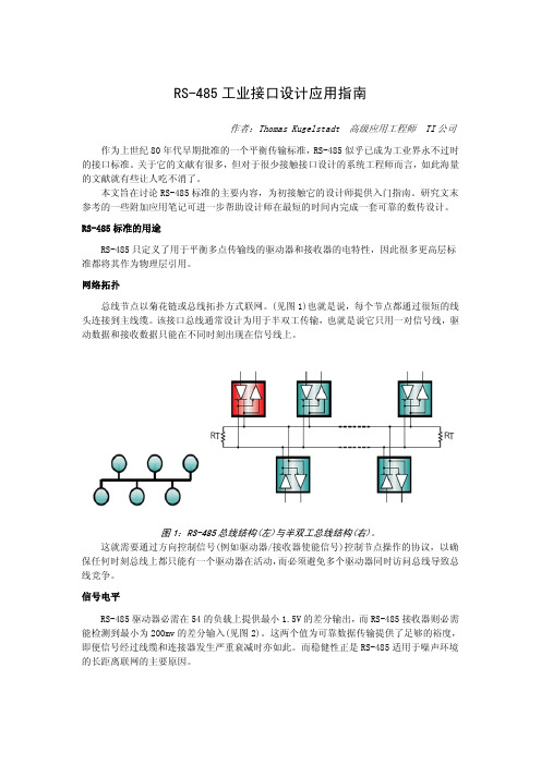
网络拓扑总线节点以菊花链或总线拓扑方式联网。
(见图1)也就是说,每个节点都通过很短的线头连接到主线缆。
该接口总线通常设计为用于半双工传输,也就是说它只用一对信号线,驱动数据和接收数据只能在不同时刻出现在信号线上。
图1:RS-485总线结构(左)与半双工总线结构(右)。
这就需要通过方向控制信号(例如驱动器/接收器使能信号)控制节点操作的协议,以确保任何时刻总线上都只能有一个驱动器在活动,而必须避免多个驱动器同时访问总线导致总线竞争。
信号电平RS-485驱动器必需在54的负载上提供最小1.5V的差分输出,而RS-485接收器则必需能检测到最小为200mv的差分输入(见图2)。
这两个值为可靠数据传输提供了足够的裕度,即便信号经过线缆和连接器发生严重衰减时亦如此。
而稳健性正是RS-485适用于噪声环境的长距离联网的主要原因。
图2:RS-485规定的最小总线信号电平。
线缆类型在双绞线上传送差分信号为RS-485应用带来了很大好处。
这是因为外部噪声源产生的噪声总是等量耦合进两根信号线中,属于共模噪声,而这能在差分接收器的输入处就被抑制掉。
工业用RS-485线缆是特性阻抗为120和22AWG的塑封非屏蔽双绞线。
图3所示为一对用于半双工网络的UTP线缆的横截面。
(完整word版)RS485,RS422设计指南
3.2.7
其它需要注意的问题.......................................................................................
14
3.3
电源和接地...............................................................................................................
14
4
维护说明
.....................................................................................................................料...........................................................................................................................................
车电子、仪器仪表等等。这项标准得到广泛接受的另外一个原因是它的通用性。RS-485标准只对接口的电气特性做出规定,而不涉及接插件、电缆或协议,在此基础上用户可以建立自己的高层通信协议。
本文档主要说明了RS485与RS422的原理以及设计应用电路中应该注意的问题。
1RS-485与RS-422性能指标及其标准
±10V
±6V
接收器敏感度
±0. 2V
±0. 2V
最小驱动器负载
100Ω
60Ω
最大驱动器数量
1
32负载单位
rs-232、rs-422与rs-485协议标准及应用概述
图8
五、RS-422 与 RS-485 传输线上匹配的一些说明 对 RS-422 与 RS-485 总线网络一般要使用终接电阻进行匹配。但在短距离与低速率下可以不用考虑终 端匹配。那么在什么情况下不用考虑匹配呢?理论上,在每个接收数据信号的中点进行采样时,只要反射 信号在开始采样时衰减到足够低就可以不考虑匹配。但这在实际上难以掌握,美国 MAXIM 公司有篇文章提 到一条经验性的原则可以用来判断在什么样的数据速率和电缆长度时需要进行匹配: 当信号的转换时间 (上 升或下降时间)超过电信号沿总线单向传输所需时间的 3 倍以上时就可以不加匹配。例如具有限斜率特性 的 RS-485 接口 MAX483 输出信号的上升或下降时间最小为 250ns,典型双绞线上的信号传输速率约为 0.2m /ns(24AWG PVC 电缆),那么只要数据速率在 250kb/s 以内、电缆长度不超过 16 米,采用 MAX483 作为 R S-485 接口时就可以不加终端匹配。 一般终端匹配采用终接电阻方法,前文已有提及,RS-422 在总线电缆终接电阻。终接电阻一般在 RS-422 网络中取 100Ω,在 RS-485 网络中取 1 20Ω。相当于电缆特性阻抗的电阻,因为大多数双绞线电缆特性阻抗大约在 100~120Ω。这种匹配方法简 单有效,但有一个缺点,匹配电阻要消耗较大功率,对于功耗限制比较严格的系统不太适合。 另外一种比较省电的匹配方式是 RC 匹配, 如图 9。 利用一只电容 C 隔断直流成分可以节省大部分功率。 但电容 C 的取值是个难点,需要在功耗和匹配质量间进行折衷。 还有一种采用二极管的匹配方法,如图 10。这种方案虽未实现真正的“匹配”,但它利用二极管的钳
目前 RS-232 是 PC 机与通信工业中应用最广泛的一种串行接口。RS-232 被定义为一种在低速率串行通
RS232、RS422、RS485串行通信协议的基础知识,看懂了,受用终身
RS232、RS422、RS485串行通信协议的基础知识,看懂了,受用终身串行通信是PLC网络常用的通信方式,正确选择接口类型和协议标准,对保证通信可靠性具有重要意义。
RS-232接口符合美国电子工业联盟(EIA)制定的串行数据通信的接口标准,原始编号全称是EIA-RS-232(简称232,RS232)。
它被广泛用于计算机串行接口外设连接。
RS-232是现在主流的串行通信接口之一。
下面给大家科普一下RS232、RS422、RS485串行通信与协议的基础知识。
1、RS232RS232是一种标准的串行物理接口,232是标识号。
每个RS232接口都有两个物理连接器(插头),有9芯和25芯插头。
其中九针插头使用较为常见,引脚功能主要是:引脚2代表RXD,引脚3代表TXD,引脚5代表GND。
RS232是半双工通讯方式,由于干扰、导线电阻等原因,通讯距离不远,低速时几十米是可以的,实际应用中一般在15米以内。
串口的引脚定义要分清,详细请看下图:2、RS485RS485最大的通讯距离为1200米,最大传输速率为10M/S。
传输速率与传输距离成反比,最大传输距离只能以100 kb/s的传输速率达到。
如果需要传输更长的距离,则需要增加RS485中继器。
RS485支持多达32个节点。
在低速、短距离、无干扰的场合可以采用普通的双绞线,反之,在高速、长线传输时,则必须采用阻抗匹配(一般为120Ω)的RS485专用电缆(STP-120Ω(for RS485 & CAN)one pair 18 AWG),而在干扰恶劣的环境下还应采用铠装型双绞屏蔽电缆(ASTP-120Ω(for RS485 & CAN) one pair 18 AWG)。
RS485接口不仅可以方便地实现两点之间数据传输,而且可以方便地用于多站之间的互联。
3、RS422和RS485接口标准电气接口电路使用平衡驱动差分接收电路以不同方式接收和发送信号,从而减少干扰。
rs422 rs485技术标准
一、起源和发展RS422和RS485是两种数字通信接口标准,它们分别由电子工业协会(EIA)制定。
RS422标准最早在1976年发布,而RS485标准则是在1983年发布的。
这两种标准在工业控制和数据采集系统中被广泛应用,因为它们能够提供可靠的长距离通信和抗干扰能力。
二、RS422技术特点1. RS422使用差分信号传输,能够在2000米的距离内实现数据传输,因此适用于需要远距离通信的场合。
2. RS422支持全双工通信,即可以同时进行发送和接收操作,这使得它可以在工业控制系统中进行可靠的数据传输。
3. RS422能够同时连接多个设备,因此在多点通信的场合下具有优势。
4. RS422的传输速率可以达到10Mbps,足够满足工业控制系统对高速数据传输的需求。
三、RS485技术特点1. RS485同样使用差分信号传输,能够在1200米的距离内进行数据传输,因此也适用于远距离通信的场合。
2. RS485同样支持全双工通信,因此在工业控制系统中同样具有可靠的数据传输能力。
3. RS485同样能够同时连接多个设备,因此也适用于多点通信的场合。
4. RS485的传输速率可以达到10Mbps,与RS422相比并无明显差异,同样足够满足工业控制系统对高速数据传输的需求。
四、RS422和RS485的比较1. RS422和RS485在通信距离和传输速率上几乎没有明显差异,都能够满足工业控制系统的需求。
2. RS422和RS485相比RS232更具抗干扰能力,因此更适用于工业环境中的数据传输。
3. RS485在多点通信的场合下具有优势,适用于多个设备同时进行通信的情况。
4. RS422和RS485的最大区别在于RS422支持全双工通信,而RS485支持半双工通信。
因此在实际应用中需要根据通信需求选择合适的标准。
五、RS422和RS485在工业控制系统中的应用1. 工业控制系统通常需要远距离数据传输和抗干扰能力,因此RS422和RS485成为了理想的通信接口标准。