光伏电缆英文版技术规格书(TUV认证)
光伏电缆英文标准

2 Pfg 1169/08.2007 Requirements for cables for use in photovoltaic-systemsContentsSeite Foreword (3)1Scope (3)2Normative references (3)3Terms and definitions (5)4Halogen-free PV-cable (6)4.1Code designation (6)4.2Characteristics (6)4.3Construction (6)4.4Test (8)4.5Guideline for use (informative) (8)4.6Current carrying capacity (8)Annex A (normative) Test of mutual influence (15)Annex B (normative) Test of absence of halogen (16)Annex C (normative) Determination of halogens – Elemental test (17)Annex D (normative) Test of long term resistance of insulation to D.C (19)Annex E (normative) Cold impact test (20)Annex F (normative) Dynamic penetration test (21)Annex G (normative) Notch propagation (23)Figure 1 – Arrangement of marking (8)Figure F.1 – Arrangement for penetration test (22)Table 1 – Current carrying capacity of PV-cables (9)Table 2 – Conversion factor for deviating temperatures (9)Table 3 – Tests for halogen free PV-cable (10)Table 4 – Requirements for halogen free insulation and sheath compounds (13)Table A.1 – Requirements (15)Table B.1 – Test method, measurement, requirements (16)Table B.2 – Test sequence (16)Table E.1 – Parameter for cold impact test (20)ForewordThis test specification contents the requirements listed in a manuscript of the working group AK 411.2.3 …Leitungen für PV-Systeme“ of the German committee for standardization (DKE). This manuscript is intended to be published as German pre-standard. Up to the date of publishing of the pre-standard this test-specification of TUV Rheinland will be used for test and assessment of cables for use in PV-systems (PV-cables).1 Scope2 PfG 1169/08.2007 applies to flexible single-core cables (cords) for use at the DC-side of photovoltaic-systems with a maximum permissible voltage of DC 1,8 kV (conductor/conductor, non earthed system).The cables are suitable for use in safety class II.It is permitted to connect these cables as multiple-construction.The cables are intended to operate at ambient temperature until 90°C2 Normative referencesThe following referenced documents are indispensable for the application of this document. For dated references, only the edition cited applies. For undated references, the latest edition of the referenced document (including any amendments) applies.IEC 60364-5-52, Erection of low voltage installations –Part 5: Selection and erection of electrical equipment –Chapter 52: Wiring systemsEN 50267-2-1, Common test methods for cables under fire conditions – Tests on gases evolved during combustion of materials from cables – Part 2-1: Procedures – Determination of the amount of halogen acid gas;EN 50267-2-2, Common test methods for cables under fire conditions – Tests on gases evolved during combustion of materials from cables – Part 2-2: Procedures – Determination of degree of acidity of gases for materials by measuring pH and conductivity;EN 50305, Railway applications – Railway rolling stock cables having special fire performance – Test methodsEN 50395, Electrical test methods for low voltage energy cables;EN 50396, Electrical test methods for low voltage energy cables;EN 60068-2-78, Environmental testing - Part 2-78: Tests -Test Cab: Damp heat, steady state (IEC 60068-2-78)EN 60216-1, Electrical insulating materials - Properties of thermal endurance - Part 1: Ageing procedures and evaluation of test results (IEC 60216-1);EN 60216-2, Electrical insulating materials – Thermal endurance properties – Part 2: Determination of thermal endurance properties of electrical insulating materials – Choice of test criteria (IEC 60216-2);EN 60228, Conductor of insulated cables (IEC 60228)EN 60332-1-2, Tests on electric and optical fibre cables under fire conditions – Part 1-2: Test for vertical flame propagation for a single insulated wire or cable – Procedure for 1 kW pre-mixed flame; (IEC 60332-1-2)EN 60684-2, Flexible insulating sleeving – Part 2: Methods of test (IEC 60684-2)EN 60811-1-1, Insulating and sheathing materials of electric cables – Common test methods Part 1-1: General application – Measurement of thickness and overall dimensions – Test for determining the mechanical properties (IEC 60811-1-1)EN 60811-1-2, Insulating and sheathing materials of electric and optical cables – Common test methods. Part 1-2: General application. Thermal ageing methods (IEC 60811-1-2)EN 60811-1-3, Insulating and sheathing material of electric and optical cables – Common test methods – Part 1-3: General application – Methods for determining the density – Water absorption tests – Shrinkage test (IEC 60811-1-3)EN 60811-1-4, Insulating and sheathing materials of electric and optical cables – Common test methods. Part 1-4: General application. Tests at low temperature. (IEC 60811-1-4)EN 60811-2-1, Insulating and sheathing materials of electric and optical cables – Common test methods – Part 2-1: Methods specific to elastomeric compounds – Ozone resistance, hot set and mineral oil immersion tests (IEC 60811-2-1)EN 60811-3-1, Insulating and sheathing materials of electric cables – Common test methods Part 3-1: Methods specific to PVC compounds – Pressure test at high temperature, test for resistance to cracking (IEC 60811-3-1)HD 22.13, Rubber insulated cables of rated voltages up to and including 450/750 V Part 13: Single and multicore flexible cables, insulated and sheathed with crosslinked polymer and having low emission of smoke and corrosive gases;HD 605, Power cables – Part 605: Additional test methodsHD 60364-7-712Electrical installations of buildings – Part 7-712: Requirements for special installations or locations – Solar photovoltaic (PV) power supply systems (IEC 60364-7-712, modified)3 Terms and definitionsFor the purposes of this document, following definitions apply.3.1 Terms for test procedure3.1.1Type test (symbol T)Tests required to be made before supplying a type of cable covered by this standard on a general commercial basis, in order to demonstrate satisfactory performance characteristics to meet the intended application. These tests are of such a nature that, after they have been made, they need not be repeated, unless changes are made in the cable materials or design or manufacturing process which might change the performance characteristics.3.1.2sample tests (symbol S)Tests made on samples of completed cable or components taken from a completed cable, at a specified frequency, so as to verify that the finished product meets the specified requirements.3.1.3Routine tests (symbol R)Tests made by the manufacturer on each manufactured length of cable to check that each length meets the specified requirements3.2Rated voltageThe rated voltage of the cable determines the construction and the tests of the cable with regard to the electrical properties.The rated voltage is designated by two values of frequency voltage: U0/U in VoltU0 rated power frequency voltage between conductor and earth (metallic screen of cable or ambient medium);U rated power frequency voltage between two conductors of a multipole cable or of a system of single core cables.The rated voltage of the cable for a given application shall be suitable for the operating conditions in the system in which the cable is used.This requirement is applicable for both U o and UThe rated voltage between two conductors in a DC-system shall not exceed the 1,5 time value of rated voltage U of the cable, and the rated voltage between conductor and earth shall not exceed the 1,5 time value of rated voltage U o of the cable.NOTE The operating voltage of a system may exceed is rated voltage permanent for 20%. A cable may be operated with a voltage which value is 20% higher than rated voltage under condition that the rated voltage is not less than the rated voltage of the system.3.3DC sidepart of a PV installation from a PV cell to the DC terminals of the PV inverter3.4open-circuit voltage under standard test conditions U OC STCvoltage under standard test conditions across an unloaded (open) PV module, PV string, PV array, PV generator or on the DC side of the PV inverter3.5short-circuit current under standard test conditions I SC TCshort-circuit current of a PV module, PV string, PV array or PV generator under standard test conditions4 Halogen free PV-cable4.1 Code designationPV1-F4.2 Characteristics4.2.1 Rated voltageAC U0/U 0,6/1 kVDC 1,8 kV (conductor-conductor, non earthed system, circuit not under load).If the cable is used in DC-systems the rated voltage between two conductors shall not exceed the 1,5 time value of rated voltage U of the cable. In with single-phase earthed DC-systems this value shall be multiplied with factor 0,5.4.2.2 Temperature rangeAmbient temperature: –40 °C to +90 °CMax. temperature at conductor: 120 °CThe cables are intended to operate at ambient temperature until 90°C. For this a temperature index of 120°C applies to the insulation and the sheath, based on EN 60216-1 (20.000h, 50% residual elongation).Note The expected period of use is 25 years.The permitted short-circuit-temperature refer to a period of 5s is 200°C.4.3 Construction4.3.1 ConductorNumber of conductors: 1The conductor shall be class 5, according to EN 60228.The single wires must be tinned.Preferred diameters: 2,5, 4, 6, 10, 16 mm24.3.2 Separation layerA separation layer of a suitable halogen free material may be applied around the conductor.4.3.3 InsulationThe insulation shall be a suitable halogen free material applied around the conductor.The insulation shall be extruded and shall consist of one or several adjacent adherent layers. It shall be solid and homogeneous, it must be possible to remove it without damage to the insulation itself, to the conductor and to the tin coating.The insulation shall be smooth, consistently applied and largely circular. Compliance shall be checked by inspection and by manual test.The wall thickness of insulation is specified by the manufacturer, but it must not fall short of the minimum value of 0,5mm.4.3.4 Separation layerA separation layer of a suitable halogen free material may be applied around the insulation.4.3.5 SheathThe core must be covered by a sheath.The sheath around the core must be of a suitable halogen free material.The sheath shall be extruded and shall consist of one or several adjacent adherent layers. The sheath shall be smooth and consistently applied.The wall thickness of sheath is specified by the manufacturer, but it must not fall short of the minimum value of 0,5mm.4.3.6 Outer diameterThe average value of the outer diameter shall be within the limits specified by the manufacturer.4.3.7 Multiple constructionEach single-core cable in a multiple construction shall pass the requirements of this document. Each additional component in a multiple construction shall pass the requirements of this document.4.3.8 Marking4.3.8.1 GeneralThe cable shall be marked as follows:a) Trademark;b) Code designation;c) Rated diameter.Marking may be by printing or by reproduction in relief on or in the sheath.4.3.8.2 TrademarkCables shall be provided with an indication of the manufacturer, which consist of a consecutively marking with company name or company sign or with (if trademarked) an identification number.4.3.8.3 Code designationCables shall be provided with an code designation according to 4.1 applied consecutively on sheath.4.3.8.4 Arrangement of markingEach marking is considered as consecutive if the spacing between the end of a marking and the begin of the following identical marking does not exceed following value:– 550mm, for marking on sheath or outer jacket.Following figure shows an example of marking on sheath.Figure 1 – Arrangement of marking4.3.8.5 DurabilityPrinted markings shall be durable. Compliance with this requirement shall be checked by the test given in 5.1 of EN 50396.4.3.8.6 LegibilityEach marking shall be legible.4.4 TestCompliance with the requirements of 4.3 shall be checked by visual inspection and tests according to table 3.4.5 Guideline for use (informative)Cables according to this standard are intended for use in PV-systems according to EN 60364-7-712.4.6 Current carrying capacityAmbient temperature: 60°CMax. temperature at conductor: 120 °CTable 1 – Current carrying capacity of PV-cablesKind of installationRated diameter Single cable free inair Single cable onsurfacesTo cables adjacent onsurfacesmm2 A A A 1,5 30 29 24 2,5 41 39 33 4 55 52 44 6 70 67 57 10 98 93 79 16 132 125 107 25 176 167 142 35 218 207 176Table 2 – Conversion factor for deviating temperaturesAmbient temperature Conversion factor°CUp to 60 1,0070 0,9180 0,8290 0,71100 0,58110 0,41Table 3 – Tests for halogen free PV-cable1 23 45Test method described in Ref. No. TestRequirementsCategoryof teststandardclause1 Electrical tests1.1 Resistance of conductorsT,S EN 50395 5 1.2 Voltage test on completed cable with AC or DC T,S EN 503956– AC-test-voltage kV– DC- test-voltage kV Length of sample m Duration of testmin Temperature of the water°C 6,5 15 20 5 20 ± 5 1.3 Absence of faults at complete cable – AC-test-voltage kV 10 R EN 50395 10 1.4Surface resistance of sheath – Minimum value Ω 109 TEN 50395111.5Insulation at complete cable Length of sample m Duration of testh Temperature of the water °C – Minimum value at 20 °C Ω ⋅ cm – Minimum value at 90 °CΩ ⋅ cm5 2 20± 5 1014 1011 T EN 50395 81.6 Long term resistance of insulation to d.c. T Annex D2 Constructional and dimensional tests2.1 Checking of compliance with constructional provisionsT,S Inspection and manual tests2.2 Measurement of thickness of insulation T,S EN 50396 4.1 2.3 Measurement of thickness of sheath T,S EN 503964.2 2.4 Measurement of overall dimensions 2.4.1 – Mean valueT,S EN 50396 4.4 2.4.2 –Ovality%≤ 15 T,S EN 50396 4.4 3 Pressure test at high temperature at complete cable T EN60811-3-13.1 Test conditions:– temperature°C 140 ± 3 – duration of heating under load min240 – Coefficient k 0,6 3.2 Results to be obtained:– depth of penetration, max.%50 – Voltage test 10 min after exculpation andcoolingTable 4, 1.24 Damp heat test T EN 60068-2-784.1 Test conditions:– temperature °C 90 – duration h 1000 – relative humidity %85 4.2 Results to be obtained:– variation of tensile strength max. % – 30– variation of elongation at breakmax. %– 30No. of test standard clause 5 Resistance against acid and alkalineT EN 60811-2-1 10 solution5.1Chemical stressacid: N-Oxal-acidalkaline solution: N-sodium hydroxide solutiontemperature °C 23duration h 1685.2Tensile strength:variation, max. % ± 305.3Elongation at break, min. % 1006 Test of influence T Annex A7 Cold impact test at –40 °C T Annex E8 Cold bending testT EN 60811-1-4 8.2 Diameter of cable < 12,5 mm8.1 Test conditions:– temperature °C –40 ± 2– duration of conditioning h 16 EN 60811-1-4 8.2.3 8.2 Results to be obtained Absence ofcracks9 Cold elongation testTable 3 Diameter of cable ≥ 12,5 mm10 Ozone resistance at complete cable T10.1 Method B EN 50396 8.1.3– temperature °C 40 ± 2– relative humidity % 55 ± 5– duration h 72(200 ± 50) × 10–6– Ozone concentration %(by volume)10.2 Results to be obtained Absence ofcracks.11 Weathering/UV-resistance T HD 605/A1 2.4.20 11.1 Conditions:– duration h 720– temperature °C63(Black-Standard-temperature)– relative humidity % 6560 ± 2– min. power at W/m2wavelength 300 nm to 400 nm– duration spraying/drying min 18/102Results to be obtained Absence ofcracks.12 Dynamic penetration test T Annex F13 Notch propagation T Annex GNo. of test standard clause 14 Shrinkage test at complete cable T EN 60811-1-3 11((sheath)) 14.1 Conditions:– temperature °C 120– duration h 1– Distance L of sample mm 30014.2 Results to be obtained:– Maximum shrinkage. % 215 Test under fire conditionsT, S EN 60332-1-215.1 Test for vertical flame propagation at completecable15.2 Assessment of halogen T, S15.2.1 Absence of halogen Annex B 15.2.2 Determination of halogens – Annex CTable 4 – Requirements for halogen free insulation and sheath compounds1 2 3 4567Test method described in Type of compound Ref. No. TestUnitstandardclauseinsulationsheath1 Mechanical characteristics1.1Properties before ageingEN 60811-1-19.2 1.1.1 Values to be obtained for the tensile strength:– median, min.N/mm 2 6,5 8,0 1.1.2 Values to be obtained for the elongation atbreak: – median, min.%125 125 1.2Properties after ageing in ovenEN 60811-1-28.1 1.2.1 Ageing conditions: – temperature °C 150 ± 2 150 ± 2– duration of treatmenth 7 × 24 7 × 24 1.2.2 Values to be obtained for the tensile strength:c – median, min. N/mm 2 – –– variation, max.% –30a –30a 1.2.3 Values to be obtained for the elongation atbreak:c – median, min. % – – – variation, max. %– 30a – 30a 1.3 Hot set test dEN 60811-2-19 1.3.1 Conditions– Temperature °C 200± 3 200± 3 – Time under load min 15 15– mechanical stressN/cm 2 20 20 1.3.2 Values to be obtained – elongation under load, max.% 100 100 – permanent elongation after cooling, max. % 25 25 1.4Thermal endurance propertiesEN 60216-21.4.1 ConditionsEither test of elongation at break or bending test shall be performed.– Temperature index 120 120 – elongation at break c % 50 50 – bending test EN 50305 7.2 2 D 2 D 1.5Cold elongation testEN 60811-1-48.4 1.5.1 Conditions: – temperature °C–40 ± 2–40 ± 2– durationh EN 60811-1-4 8.4.4 und 8.4.5bb1.5.2 Values to be obtained:– elongation at break, min.%30301 2 3 4 5 6 7Test method described in Type of compound Ref. No.TestUnitstandardclauseinsulationsheatha No positive value for variation fixed.b See test method in column 4 and 5.c This test shall be performed at test samples of insulation and sheath compound. d This test shall be performed only at cross-linked insulation and sheath compoundTest of mutual influenceA.1 ConditionsTest samples must be aged for 7 days at (135 ± 2) °C at conditions according to table 2A.2 RequirementsAfter ageing the insulation and the sheath shall pass the requirements of table A.1.Table A.1 – RequirementsTests units insulation sheath Tensile strength – median, min. N/mm2– –– variation a, max. % ± 30 –30 b Elongation at break – median, min. % – –– variation a, max. % ± 30 ± 30a Variation: difference between the median value obtained after ageing and the median value obtained without ageing expressed as apercentage of the latter.b Positive tolerances are not limited.Test of absence of halogenB.1 Requirements of extruded materialsInsulation and sheath shall pass the requirements as follows: a) Type testThe material must be tested as described in table B.1.Table B.1 – Test method, measurement, requirementsTest methodMeasurementrequirements1 EN 50267-2-2 pH and conductivity pH ≥ 4,3 undconductivity ≤ 10 µS/mm a 2 EN 50267-2-1 Chlorine- and Bromine content, expressed in HCI ≤ 0,5 %3aAnnex CHalogen: FluorideIf negative the test should be finished. No further test is necessary.The material shall be accepted.If positive, test of 3b shall be performed 3bEN 60684-2Fluoride content≤ 0,1 %a If discrepancies regarding conductivity appear, e.g. the recommended value is exceeded even if there is compliance with therecommended ph-value, other test method may be applied after agreement with all participants.The material shall be tested according to test sequence of table B.2.Table B.2 – Test sequenceTest method MeasurementValue ResultIf negative the test should be finished. No further test is necessary.The material shall be accepted. Phase 0 HD 22.13,Annex CHalogen: Fluoride, Chloride and BromideIf positive continue with phase 1.< 4,3 The material shall be revised. pH ≥ 4,3Conductivity shall be tested. conductivity ≤ 2,5 µS/mmThe material shall be accepted. No further test is necessary.conductivity > 10 µS/mm The material shall be revised.Phase 1 EN 50267-2-2 conductivity (s)> 2,5 µS/mm but ≤ 10 µS/mm Test according to EN 50267-2-1 shall be performed > 0,5 % The material shall be revised.Phase 2 EN 50267-2-1Chlorine- and Bromine content, expressed in HCI≤ 0,5 % Test according to EN 60684-2 shall be performed. > 0,1 % The material shall be revised. Phase 3 EN 60684-2Fluoride content≤ 0,1 %The material shall be accepted.Determination of halogens – Elemental testWarningOwing to its potentially hazardous nature, the fusion operation should be carried out in a fume cupboard, using a safety screen.C.1 EquipmentBunsen burner3 small/medium soda glass test tubes (approximately 50 mm x 10 mm)Test tube holderEvaporating basin/mortarWire gauze;FunnelFilter paperC.2 MaterialsUnknown sampleSodium metalDilute nitric acid (5 %)Aqueous silver nitrate (5 %)Dilute ammonia (10 %)Freshly made up zirconium-alizarin red S reagentGlacial acetic acidAcid/pH indicator papersC.3 ProcedureC.3.1 Sodium fusionPlace 200 mg – 250 mg of the sample into the bottom of a small soda glass test tube. Add 10 ml of distilled/de-ionized water to the evaporating basin and place this in the fume cupboard behind the safety screen. Whilst holding the test tube firmly with the test tube holder at an angle of 45° - 60° to the vertical, introduce a piece of freshly cut, clean sodium (about the size of a small pea) (200 mg – 250 mg) into the mouth of the test tube without allowing it to come into contact with the sample. With the safety screen in place, heat the sodium gently until it melts and runs down on to the sample (there may be a vigorous reaction when the molten sodium reaches the sample if halogens are present). Heat the tube gently for about 1 min, then more strongly until the lower 20 mm of the tube glows red hot. Plunge the red hot tube into the water in the evaporating basin, immediately placing the gauze on top. (The gauze prevents any loss of material when the tube shatters on contact with the water.) Allow any non reacted sodium to react before grinding up the solution and glass. Filter, and separate the filtrate into two equal portions.C.3.2 Chlorine and bromineTo the first portion of the filtrate, add sufficient nitric acid to make the solution acidic. Boil this solution until its total volume has been reduced by half (this is to remove any HCN or H2S, if present, which would interfere with the test). Add 1 ml silver nitrate solution; a white or yellowish-white precipitate indicates the presence of halogen (Cl, Br) in the original sample. (If the liquor is decanted, and the precipitate is white and readily soluble in dilute ammonia, then chloride is present.)C.3.3 FluorineTo the second portion of the filtrate, acidify with glacial acetic acid. Boil this solution until its total volume has been reduced by half. Add 2 to 3 drops freshly prepared zirconium lake reagent (equal volumes of: a) Alizarin solution: 0,05 g Alizarin Red-S in 50 ml distilled water, b) Zirconium solution: 0,05 g zirconium nitrate in 10 ml concentrated HCl diluted with 50 ml distilled water). Heat at 40 °C for 1 h. The presence of fluoride is indicated by the red/pink colouration being bleached to yellow.Test of long term resistance of insulation to D.C.A test sample with a length of minimum 5m shall be immersed into water containing 3 % NaCl. Further on minimum 300mm of the sample shall stick out of the water. The water-bath shall be retained for (240 ± 2) h at a high temperature of (85 ± 2) °C and a D.C.-voltage 0,9kV shall be applied between conductor and water whereby the conductor shall be connected to the positive potential.The current of this circuit shall be measured with a period of not more than 24h. If possible a continuous measurement shall be preferred.The measured values shall be recorded in a time-current-curve which identifies a stable progress.NOTE A stable progress is e.g. an increase of less than 10% of leakage current on the average for a time of 24h (This is part of the inspection based on practical experiences)After storing the samples shall be taken out of the salt-water-solution and a voltage test according to Ref.-No. 1.2 of table 1 shall be performed. The test voltage shall be the rated voltage (U) of the cable.Cold impact testThe cold impact test shall be performed at –40°C according to clause 8.5 of EN 60811-1-4, but the mass of hammer, the mass of test probe and the height shall comply with table 2.Table E.1 – Parameter for cold impact testDiameter of cable (D) Mass of hammer Mass of test probe height mm g g mmD < 15 1 000 200 10015 < D≤ 25 1 500 200 150D > 25 2 000 200 200The inner and outer surface of sheath shall be inspected with normal or corrective visual faculty without magnification. Only the outer surface of the insulation shall be inspected. No cracks must be determinedAnnex F(normative)Dynamic penetration testA test apparatus for pull test (or a equivalent apparatus) shall be operated in pressure modus and shall be equipped with a measuring device which is able to record the force of penetration of the spring-steel-needle (see figure F.1b) through the insulation or sheath of a completed cable. A circuit with low voltage which finish the test at the moment when the needle penetrates the insulation or the sheath and makes contact with the conductor shall be added.The test shall be performed at room temperature. The force applying to the needle shall be increased continuously with 1 N/s until contact with the conductor has been made. 4 tests at each sample shall be performed and the force at the moment of contact shall be recorded. After each test the sample shall be moved forward and shall be turned clockwise for 90°.The mean value of the 4 test results must not be less than the minimum value F determined with following formulaF = 50 ⋅DD diameter of cable in mmDimensions in mma) detail X(edges not broken or rounded, without ridge)b) detail YCaption 1 N.A. 2 N.A. 3 Load 4 Clamp 5 Sample6Mounting surface7 Fixing screw 8 Blade9 Shoulder with sufficient depth for testing the insulation 10 Needle of spring steel 11SampleFigure F.1 – Arrangement for penetration testAnnex G(normative)Notch propagationThree samples of the cable shall be notched, to a depth of 0,05 mm of the insulation or sheathing, at four points equally spaced with respect to one another around the circumference and 25 mm apart along the length, and in a plane mutually perpendicular to the conductor.One of the samples shall be conditioned at -15 °C, one at ambient temperature and one at 85 °C, in all cases for 3 h, after which time they shall be wound on to a mandrel, (3 ± 0,3) times the minimum specified diameter of the cable, whilst at the conditioning temperature. The notched sample shall be wrapped around the mandrel such that at least one notch is on the outside of the cable.The sample shall be allowed to return to ambient temperature and then subjected to the voltage test given in no. 1.2 of Table 1 but at half the rated voltage U0.。
光伏电缆B(特性参数)

1、电缆型号规格Specification Type:PV1-F 1*1.5mm2产品标准Standard:2PfG 1169/08.07通过德国TUV认证It is approvalled by TUV证书号Certificate NO.:2、电缆结构:3、电缆特性:产品标准Standard:2PfG 1169/08.07通过德国TUV认证It is approvalled by TUV 证书号Certificate NO.:2、电缆结构:3、电缆特性:产品标准Standard:2PfG 1169/08.07通过德国TUV认证It is approvalled by TUV 证书号Certificate NO.:2、电缆结构:3、电缆特性:产品标准Standard:2PfG 1169/08.07通过德国TUV认证It is approvalled by TUV 证书号Certificate NO.:2、电缆结构:3、电缆特性:产品标准Standard:2PfG 1169/08.07通过德国TUV认证It is approvalled by TUV 证书号Certificate NO.:2、电缆结构:3、电缆特性:产品标准Standard:2PfG 1169/08.07通过德国TUV认证It is approvalled by TUV 证书号Certificate NO.:R2、电缆结构:3、电缆特性:产品标准Standard:2PfG 1169/08.07通过德国TUV认证It is approvalled by TUV 证书号Certificate NO.:R2、电缆结构:3、电缆特性:产品标准Standard:2PfG 1169/08.07通过德国TUV认证It is approvalled by TUV 证书号Certificate NO.:R2、电缆结构:3、电缆特性:产品标准Standard:参照2PfG 1169/08.07 2、电缆结构:3、电缆特性:产品标准Standard:参照2PfG 1169/08.07 2、电缆结构:3、电缆特性:产品标准Standard:参照2PfG 1169/08.07 2、电缆结构:3、电缆特性:产品标准Standard:参照2PfG 1169/08.07 2、电缆结构:3、电缆特性:1、电缆型号规格Specification Type:PV-F 1*150mm2产品标准Standard:参照2PfG 1169/08.072、电缆结构:3、电缆特性:产品标准Standard:参照2PfG 1169/08.07 2、电缆结构:3、电缆特性:产品标准Standard:参照2PfG 1169/08.07 2、电缆结构:3、电缆特性:产品标准Standard:2PfG 1169/08.07通过德国TUV认证It is approvalled by TUV 证书号Certificate NO.:R 501318862、电缆结构:3、电缆特性:1、电缆型号规格Specification Type:PV-F 2*1.5mm2产品标准Standard:2PfG 1169/08.07通过德国TUV认证It is approvalled by TUV证书号Certificate NO.:R 501318862、电缆结构:3、电缆特性:产品标准Standard:2PfG 1169/08.07通过德国TUV认证It is approvalled by TUV 证书号Certificate NO.:R 501318862、电缆结构:3、电缆特性:产品标准Standard:2PfG 1169/08.07通过德国TUV认证It is approvalled by TUV 证书号Certificate NO.:R 501318862、电缆结构:3、电缆特性:产品标准Standard:2PfG 1169/08.07通过德国TUV认证It is approvalled by TUV 证书号Certificate NO.:R 501318862、电缆结构:3、电缆特性:4、结构简图:Sketch:护 套sheath 导 体conductor光伏电缆PV-Cable 1、电缆型号规格Specification Type:PV-F 3*4.0mm2产品标准Standard:参照2PfG 1169/08.072、电缆结构:3、电缆特性:。
PV-电缆(光伏组件用电缆)

PV-电缆(光伏组件用电缆)1、技术规范PV-电缆(光伏组件用电缆)目前尚无国家或行业标准,本试验技术规范所涉及到的要求来自于德国标准化委员会PV-系统用电线K411.2.3工作组的初稿。
这个初稿将作为德国国家标准报批稿进行发布。
德国莱茵TUV(上海)将用此技术规范对PV-电缆的性能进行检测和评估。
在德国莱茵TUV公司内部此技术规范的文件编号为2PfG 1169/08.2007。
2、使用范围2PfG 1169/08.2007适用于最高允许1.8kV(线芯对线芯,非接地系统)直流电压、在光伏系统中CD侧使用的单芯软电缆(电线)。
该产品适合于Ⅱ类安全等级下使用。
电缆运行的环境温度最高到90℃。
电缆可以多根并联使用。
3、特殊名词术语PV 系统(photovoltaic system):光伏系统(太阳能系统)。
DC侧(DC side):光伏装置中从光伏电池到光伏换流器直流端子之间的部分。
标准试验条件下的开路电压(UOC STC):在标准试验条件下,未加载(开路)的光伏组件、光伏电线、光伏列阵、光伏发电机或光伏换流器直流侧的电压。
标准试验条件下的短路电流(ISC TC):在标准试验条件下,光伏组件、光伏电线、光伏列阵或光伏发电机的短路电流。
4、无卤PV-电缆的基本信息4.1电缆型号PV1-F4.2电缆特性●额定电压:AC U0/U=0.6/1kVDC 1.8kV(线芯对线芯,非接地系统,没有负载下的回路)如果电缆使用在直流系统中,其导体间的额定电压应不大于电缆AC额定值U的1.5倍。
在单相接地直流系统中,此数值应乘以0.5的系数。
●温度范围:环境温度:-40℃到+90℃导体最高工作温度:120℃电缆运行的环境温度最高到90℃。
依据EN60216-1标准进行考核,其绝缘和护套的温度指数是120℃。
期望使用寿命是25年5秒钟的短路温度是200℃4.3电缆结构●导体导体芯数:1导体是EN60228(IEC60228、GB/T3956)中的第5类导体,而且必须是镀锡的。
明超电缆pv1f1x4 技术参数

明超电缆pv1f1x4 技术参数规格型号:PV1-F 1×4mm2是遵循TUV 2 PfG 1169/08.2007标准规范的一种直流太阳能光伏电缆,适用于光伏电站直流电路连接和光伏连接器的加工使用。
代表截面为4平方毫米的单芯光伏电缆线,俗称4平方光伏线,其详细含义:PV是英语photovoltaic的缩写,翻译过来是指光伏的意思;PV1-F 1×4mm 中第一个1指的是电压0.6/1KV;F是指采用的是第五类导体,类似的型号表达有:H05VV-F等;PV1-F 1×4mm 中第二个1是指一芯,单芯的意思;4mm表示线缆横截面为4平方毫米;技术参数:型号规格 mm2 导体根数导体直径成品外径mmPV1-F 1.5 30 0.25 5 ~ 5.5PV1-F 2.5 51 0.25 5.5 ~ 6PV1-F 4 56 0.3 6 ~ 6.5PV1-F 6 84 0.3 6.8 ~7.3PV1-F 10 80 0.4 8.5 ~9.2PV1-F 16 128 0.4 10.2~ 11.2PV1-F 25 199 0.4 11.9~ 12.9PV1-F 35 278 0.4 13.2~ 14.2PV1-F 50 396 0.4 15.5~ 16.5PV1-F 70 558 0.4 17.7~ 18.7PV1-F光伏电缆主要技术参数:(1)工作温度–40℃~120℃弯曲半径≤5D短路温度电缆短路时(较长持续的时间不*过5S)(2)导体较高温度不*过150℃耐气候性符合UV(UVISO 4892-2A)(3)耐臭氧符合IEC60811-2-1阻燃特性单根垂直燃烧(符合IEC60332-1)具有优异的耐酸碱性和耐湿热性PV1-F光伏电缆电缆规格:(1)PV1-F-1*4光伏电缆即单芯4平方(2)PV1-F-1*2.5光伏电缆即单芯2.5平方(3) PV1-F-1*1.5光伏电缆即单芯1.5平方(4)PV1-F-1*10光伏电缆即单芯10平方(5)PV1-F-1*16光伏电缆即单芯16平方(6)PV1-F-1*25光伏电缆即单芯25平方(7)PV1-F-1*35光伏电缆即单芯35平方(8)PV1-F-1*50光伏电缆即单芯50平方(9)PV1-F-1*70光伏电缆即单芯70平方导线:镀锡铜多股线,符合IEC60228+EN60228,VDE0295,5级绝缘: 低烟无卤阻燃聚烯烃绝缘材料UL4703护套颜色: 黑/黑,黑/蓝,红/红,蓝/黑,黑/红,红/黑,蓝/蓝,其他可订购外护套: 低烟无卤阻燃聚烯烃护套材料UL4703护套颜色:黑/黑,黑/蓝,红/红,蓝/黑,黑/红,红/黑,蓝/蓝,其他可订购额定电压: Uo/U 0.6/1kv 测试电压: 6500V较小弯曲半径φ≤12mm: 3×D φ>12mm: 4×D使用温度环境温度:达+90℃电缆较高温度: +120℃铺设时: -30/+120℃固定铺设: -45/+120℃短路时: +250℃无卤: 不含盐酸符合EN50627-2-1,不含氟符合EN60684-2阻燃性:阻燃自熄符合IEC60332-1-2+EN60332-1-2光伏电缆的应用范围:太阳能装置的连接电缆,即可以在不同的气候条件下户外安装使用,又可以适应干燥,潮湿的室内工作环境。
光伏组件tuv认证标准 -回复

光伏组件tuv认证标准-回复光伏组件TUV认证标准主要是指国际电工委员会(International Electrotechnical Commission,简称IEC)发布的太阳能光电组件技术规范,这是目前光伏组件业界公认的国际标准之一。
本文将一步一步回答有关光伏组件TUV认证标准的问题。
第一步:了解TUV认证机构和目的TUV认证是由德国著名的技术审核、检验和认证公司TUV莱茵(TUV Rheinland)所颁发的认证。
TUV莱茵是全球著名的第三方认证机构之一,以其严格的审核和认证标准在业界享有盛誉。
TUV认证的目的是确保光伏组件的质量、安全性和可靠性,保护消费者的权益。
第二步:了解光伏组件TUV认证的标准光伏组件TUV认证遵循IEC标准,其中最为常见的是IEC 61215和IEC 61730两个系列认证。
IEC 61215是太阳能光电(PV)电池模组的设计和性能的标准,并测试光伏组件在各种条件下的耐久性和可靠性。
IEC 61730则是关于光伏组件的安全性标准,要求在电气、机械和防火方面具备符合要求的性能。
第三步:准备认证申请材料准备认证申请材料是获得TUV认证的重要步骤。
申请材料通常需要包括光伏组件的技术规范、性能数据、电气和机械安全测试报告等。
此外,还需要提供光伏组件制造商的质量管理体系文件,例如ISO 9001认证等。
第四步:组织认证测试认证测试是获得TUV认证的关键步骤之一。
认证测试通常由认证机构的工程师进行,包括性能测试、电气测试、机械测试和安全测试等。
性能测试检查光伏组件的功率输出、温度特性和光正比特性等。
电气测试检查光伏组件的电气参数,例如最大功率点和开路电压等。
机械测试和安全测试则包括抗风压、防火性能和机械强度等。
第五步:评估认证结果认证测试完成后,认证机构将评估测试结果,并判断光伏组件是否符合TUV认证标准。
如果通过评估,认证机构将颁发TUV认证证书,确认光伏组件的质量、安全性和可靠性。
TUV 认证光伏电缆
≥0.5
≥0.6
≥0.7
≥0.8
≥0.9
外径Cable OD./Flat
mm
11*5
13*6
15*7
20*9
22*10
导体电阻Conductor resistance(20℃)
Ω/km
≤9.45
≤7.98
≤3.30
≤1.91
≤1.24
试验电压Voltage test on completed cable
2×4,0
2×6,0
2×10
2×16
铜丝结构Number/ Diam来自ter of wiresNO./mm
2*50/0.25
2*52/0.3
2*84/0.3
2*142/0.3
2*128/0.4
绝缘壁厚Thickness of the Insulation
mm
≥0.5
≥0.6
≥0.7
≥0.8
≥1.0
护套壁厚Thickness of the Sheath
其他说明
项 目
Item
单 位
Unit
技术参数
Technical parameter
工作温度Rated temperature
℃
-40~﹢90
工作电压Rated Rating
ac/dc(kv)
0.6~1.0/1.8
芯数Cable Core
No.
2
标称截面Cross-Section Area
mm 2
2×2,5
TUV认证光伏电缆介绍
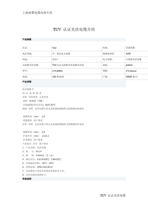
产品参数
认证:
TUV
电流:
直流电缆
电压等级:
中、低压电力电缆
光伏逆变器TUV认证文件清单

Main board 主板, Controlling board 控制板, Drivering board 驱动板等:1-2 pcs
Environment and Testing facilities requirement on site 场地及设备要求 1. 2. 3. 4. 5. 6. 7. 8. Power analyzer 功率电能质量分析仪 Solar simulator / DC power supply 太阳能模拟器或直流电源 Grid simulator / AC programmable power supply 模拟电网或交流可编程电源 RLC load 模拟电网负载 Temperature and Humidity Chamber 高低温潮态箱 Temperature testing recorder 温度测试仪 4 channels oscillograph 示波器 etc 等。
Product:
Grid-connected PV Inverter
Type Designation: 2KTL, 3KTL, 4KTL, 4.6KTL
General Documents 通用文件资料 Application Form 申请表 General Agreement 项目总和约 Trademark Declaration 商标声明 OEM Declaration OEM 型号商标声明 Prototype Declaration 原型机声明 EMC, WEEE, RoHS Declaration 声明 PAH compliance material list PAH 材料清单 Technical Documents 技术资料 Rating label 铭牌 English 英文 User’s manual 说明书 English 英文 German 德文 German 德文
光伏电缆说明书

光伏电缆说明书应用本产品适用于极端气候条件下,各室内室外太阳能光伏系统电路连接。
标准2PfG 1169/08.2007 (PV1-F)光伏电缆的使用寿命,光伏电缆的型号规格结构导体: 符合DIN VDE 0295 and IEC 60228 Class 5的绞合镀锡铜导线绝缘: 电子束交联,低烟无卤阻燃复合物护套: 电子束交联,低烟无卤阻燃复合物, 黑色电气性能额定电压U0/U: 0.6/1 kV AC; 0.9/1.5 kV DC最大允许交流电电压: 1.8 kV DC (导体/导体,无接地系统, 电路无负荷时) 绝缘电阻: 1000 MΩ-km火花试验: 6000 Vac (8400 Vdc)能耐电压: 6500 Vac for 5 min热性能室内温度: -40℃ ~ +90℃导体的最大温度: IEC/EN 60216-1 120℃ (20000h)短路温度: 200℃/5 s耐热性试验: EN 60216-2 (温度为+120° C)高温压力试验: EN 60811-3-1耐湿热: EN60068-2-78,85% 湿度机械性能最小弯曲半径: 4×OD (fixed), 5×OD (flexing)动态渗透: 2 PfG 1169/08.2007 附录 F槽传播: 2 PfG 1169/08.2007 附录G拉伸强度以及绝缘层和护套的延伸率: EN 60811预期使用寿命: 25 年化学性能耐臭氧: EN 50396 part 8.1.3 方法B耐风化和紫外线: HD 605/A1耐氨良好的耐油和耐化学腐蚀良好的耐磨损和耐老化性能耐酸碱: 按照EN 60811-2-1 (草酸&氢氧化钠)EC指标该电缆符合欧洲标准中的CE 2006/95/EC(低压规定)和RoHS 2002/95/EC(限制使用有害物质的相关规定)防火性能EN 50265-2-1, IEC 60332-1, VDE 0482-332-1-2, DIN EN 60332-1-2规定的阻燃性能IEC 61034, EN 50268规定的低烟性能EN 50267-2-1, IEC 60754-1规定的无卤性能EN 50267-2-2, IEC 60754-2规定的低腐蚀性气体规格和尺寸载流容量。
- 1、下载文档前请自行甄别文档内容的完整性,平台不提供额外的编辑、内容补充、找答案等附加服务。
- 2、"仅部分预览"的文档,不可在线预览部分如存在完整性等问题,可反馈申请退款(可完整预览的文档不适用该条件!)。
- 3、如文档侵犯您的权益,请联系客服反馈,我们会尽快为您处理(人工客服工作时间:9:00-18:30)。
Positive pole cable
identification
g
Negative pole cable
identification
3. Testing
a
Type Test Certificate
UNIT
SPECIFIED
permitted.
As per EN50618
Continuous Red stripe on Black oversheath
termite protection)
g
Installation
Direct buried underground
In wiring enclosure, in air
h
Minimum current
ratings
i
Minimum design life
with 90°C conductor
temperature for 10
AECOM
Darling Downs Solar Farm Procurement Specification - 1500V DC Cables and Accessories – Darling Downs Solar Farm
C Appendix
DC String Whip Data Sheet
hours per day, with
60°C air
temperature,
exposed to direct
sunlight
j
Minimum permissible mm
bending radius
(during and after
installation)
2. Construction
a
Conductor
Or
Continuous Red over-sheath without stripe
Continuous White stripe on Black oversheath
Or
Continuous Black over-sheath without stripe
TÜV 2 PfG 1990/05.12
CONTRACTOR RESPONSE
Revision A – 27-Oct-2016 Prepared for – RCR O'Donnell Griffin Pty Ltd – ABN: 78003905093
Solar Farm
Appendix C DC String Whip Data Sheet
ITEM
PARAMETER
UNIT
SPECIFIED
Quantities: Refer to document DDSF DDSF-EL-000-DWG-1501
1. General
a
Type
b
Form
Photovoltaic power cable
Revision A – 27-Oct-2016 Prepared for – RCR O'Donnell Griffin Pty Ltd – ABN: 78003905093
AECOM
Darling Downs Solar Farm
C-1
Procurement Specification - 1500V DC Cables and Accessories – Darling Downs
Single core
c
Overarching Design
Standard
EN50618
d
Rated DC Voltage
kV/kV 1.5/1.5
Uo/U
e
Individual Conductor mm² 6
CSA
f
Maximum cable outer mm 7
diameter (including
b
Insulation
c
Sheath/Jacket
d
Termite Protection
Exposed, in air with direct sunlight As per EN50618 Table A.3 25 years
< 50
As per EN50618 As per EN50618 As per EN50618 Continuous Nylon 12 Cover.
Note: No poison based impregnation/treatme nt of the sheath is
Revision A – 27-Oct-2016 Prepared for – RCR O'Donnell Griffin Pty Ltd – ABN: 78003905093
CONTRACTOR RESPONSE
AECOM
Darling Downs Solar Farm
C-2
Procurement Specification - 1500V DC Cables and Accessories – Darling Downs
Solar Farm
ITEM
PARAMETER