日本SDC-31操作说明书
SDC量热仪说明书正文
第一章仪器性能和特点1.1 应用范围本系统适用于电力、煤炭、造纸、石化、水泥、农牧、医药、科研、教学等行业或部门测定煤炭、石油产品等固体或液体可燃物质的热值。
1.2性能指标测温范围:5~44℃分辨率: 0.0001℃精密度:≤0.15%。
1.3系统特点1.3.1高度自动化、高效率1.自动调水温、称水重、自动检测总水量;2.操作简单、维护方便;3.单头氧弹,采用套压方法拴装点火丝,方便安全可靠;4.具有>100个氧弹自动识别功能。
5.单样测试时间<11min(SDC311)、<15min(SDC5015),测试速度快、环境适应能力强,提高了工作效率。
1.3.2 精密度和准确度高在操作规范的前提下,系统的精密度和准确度高。
1.3.3 操作简便1.整套系统只用一个开关控制。
2.全过程汉字提示,按照提示操作即可完成实验。
3.软件容错性好,不用担心操作有误。
4.可方便地进行高、低位发热量的计算和打印。
5.可进行多控重复样测试,自动判断误差,自动平均有效结果,允许多份打印。
6.查询功能丰富,支持模糊查询。
1.3.4 专家诊断系统1.在测试过程中,系统具有自诊断功能,能准确判断各功能部件是否正常,并明确提示用户,便于维护,确保系统正常运行。
2.看门狗和机械保护装置能全程保护防止仪器出现异常。
1.3.5 异步多控SDC量热仪测试软件允许挂接任意组合的多控SDC311量热仪和SDC5015量热仪,多控量热仪各主机间完全独立、互不干涉。
1.3.6 运行平台测控程序可运行在WindowsXP以及Windows2000操作环境下。
第二章仪器组成及工作原理2.1 仪器组成SDC量热仪主要由SDC量热仪主机、SD—YD氧弹、SD—CYQ微型充氧器、SD测控接口、SD测控软件、计算机、打印机等组成(见图2-1)。
此外,用户还可以选配电子天平、天平接口、SD天平称量软件以及相关仪器配件。
图2-12.1.1 SDC 量热仪主机1.结构示意图(见图2-2);2.特点:体积小、重量轻,自动定容水量、调节水温,环境适应能力强,操作简单方便。
永大日立电梯调试说明书
e’NT调试试运转及调整要领目录一、e’NT与NT差异对照表二、e’NT系统构成图三、e’NT的概要四、各PC板安装及工事配线确认五、各接地线连接取付实况六、R E及MOTOR配线CHECK七、作业上的注意事项八、电梯低速运转前的作业事项九、绝缘测定、PC板电压设定及调整十、低速试运转十一、高速运转前准备十二、高速运转准备十三、LINKLESS门机十四、阶高测定十五、高速确认十六、平衡电流测试十七、起动补偿调整十八、着床平层调整十九、电梯微速时间调整二十、MICRO运转水平调整二十一、乘场及车厢LED楼层显示器之点检二十二、各楼层开关门时间调整二十三、HALL LAN系统二十四、ANN操作二十五、特殊功能检查及设定二十六、车厢内照明及风扇的自动休止设定二十七、定位按钮功能二十八、PCB作业注意事项二十九、电梯命名规则三十、最终故障发生时间三十一、TCD码目录解说三十二、具体TCD码三十三、PCB连接器与端子说明.......................................1~4 (5).......................................6~8 .......................................9~18 .......................................19~21 .......................................22~23 (23).......................................24~25 .......................................25~26 (27) (28) (29).......................................30~34.......................................35~36 (36).......................................36~38.......................................38~40 (41) (42) (43) (43) (44).......................................45~51.......................................52~70.......................................70~74.......................................74~75 .......................................75~76.......................................77~79 (80) (81)…………………………………82~84…………………………………另附…………………………………85~101OP5 OP6附图一、附图二、。
SDC31参数表
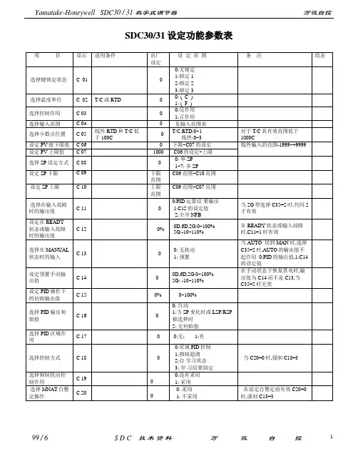
S D C30/31设定功能参数表在C显示时,低于20C的值不显示, 在F显示时,低于68F的值不显示. * * 在–200.0C 不能设定和显示,但在-200.0 C 时可以调节.注 2:在C08中显示这些内容,但当PID 范围采用时(C17=1),可显示出0~7 注3: 当远程功能选择时,PIDr 才显示,PID 范围不可采用(C17=1) 注4: 当采用抗扰动PID 采用时(C19=1)本显示出现。
.1: 参数设定的基本方法如下:(1和 键3秒使仪表进入基本参数设置状态 ( 2 ) 按 和 键来选择希望设定的参数组 ( 3 ) 按 ENT 键使仪表进入设定参数组状态 ( 4 ) 按 或 键来选择希望的参数 ( 5 ) 按 ENT 键使仪表进入参数值设定状态 ( 6 ) 按 或 键来设定希望的参数值 ( 7 ) 按 ENT 键使设定参数值存储于仪表中( 8 ) 按 2 次 DISP 键使仪表恢复到基本设定状态,当只按 1 次 DISP 键时, 仪表进入参数组显示状态.2: 启动 / 停止自整定功能 启动方法:( 1 ) 进入基本显示状态: 按DISP 健此时显示PV 值 显示SP 值 ( 2 ) 进入At (自整定)显示显示 按 MODE 健多次直到At 显示,闪动 再按 ENT 键。
( 3 ) 改变设定值,按 健使0变1,闪动 ( 4 ) 按ENT 键,闪动停止,设定值确定,AT LED 闪动,自整定启动. ( 5 )当自整定完成后,AT 灯熄灭,PID 常数自动写入仪表中.停止方法( 1 ) 进入基本显示状态: 按DISP健此时显示PV值显示SP.MV值( 2 ) 进入At(自整定)显示显示按 MODE 健多次直到At显示,闪动再按 ENT 键。
( 3 ) 。
按健使1变0,( 4 ) 按ENT 键,闪动停止,设定值确定,.( 5 ).按DISP键,恢复基本显示状态3.RUN/READY状态的切换( 例如:从readyd( 1 ) 进入基本显示状态: 按DISP健此时显示PV值显示SP.MV值( 2 ) 进入状态显示显示按 MODE 健2次无显示( 3 ) 显示按或健使显示”run”,( 4 ) 按ENT 键,状态确定,.4.本机SP(LSP) / 远程SP(LSP)的切换。
SDC量热仪说明书正文
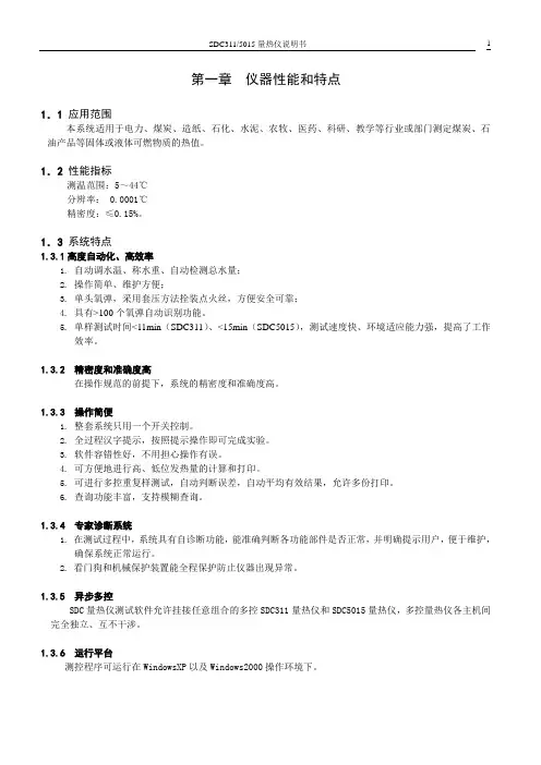
第一章仪器性能和特点1.1 应用范围本系统适用于电力、煤炭、造纸、石化、水泥、农牧、医药、科研、教学等行业或部门测定煤炭、石油产品等固体或液体可燃物质的热值。
1.2性能指标测温范围:5~44℃分辨率: 0.0001℃精密度:≤0.15%。
1.3系统特点1.3.1高度自动化、高效率1.自动调水温、称水重、自动检测总水量;2.操作简单、维护方便;3.单头氧弹,采用套压方法拴装点火丝,方便安全可靠;4.具有>100个氧弹自动识别功能。
5.单样测试时间<11min(SDC311)、<15min(SDC5015),测试速度快、环境适应能力强,提高了工作效率。
1.3.2 精密度和准确度高在操作规范的前提下,系统的精密度和准确度高。
1.3.3 操作简便1.整套系统只用一个开关控制。
2.全过程汉字提示,按照提示操作即可完成实验。
3.软件容错性好,不用担心操作有误。
4.可方便地进行高、低位发热量的计算和打印。
5.可进行多控重复样测试,自动判断误差,自动平均有效结果,允许多份打印。
6.查询功能丰富,支持模糊查询。
1.3.4 专家诊断系统1.在测试过程中,系统具有自诊断功能,能准确判断各功能部件是否正常,并明确提示用户,便于维护,确保系统正常运行。
2.看门狗和机械保护装置能全程保护防止仪器出现异常。
1.3.5 异步多控SDC量热仪测试软件允许挂接任意组合的多控SDC311量热仪和SDC5015量热仪,多控量热仪各主机间完全独立、互不干涉。
1.3.6 运行平台测控程序可运行在WindowsXP以及Windows2000操作环境下。
第二章仪器组成及工作原理2.1 仪器组成SDC量热仪主要由SDC量热仪主机、SD—YD氧弹、SD—CYQ微型充氧器、SD测控接口、SD测控软件、计算机、打印机等组成(见图2-1)。
此外,用户还可以选配电子天平、天平接口、SD天平称量软件以及相关仪器配件。
图2-12.1.1 SDC 量热仪主机1.结构示意图(见图2-2);2.特点:体积小、重量轻,自动定容水量、调节水温,环境适应能力强,操作简单方便。
数字显示调节器SDC3536使用说明书(详细篇)
數字顯示調節器 使用說明書
SDC15/25/26/35/36 用用智能編程軟件包SLP-C35 資料編號 CP-UM-5290C
與智能編程軟件包同包裝。 本書是關於使用計算機進行SDC15/25/26/35/36各種設定的軟件的說明 書。請使用SDC15/25/35/36進行裝置設計、設定的人員,務必閱讀。介紹 了安裝在計算機上的方法、操作、各種功能、設定方法。
本符號顯示使用上必須“注意”的內容。
本符號顯示必須“禁止”的內容。
本符號顯示必須執行的“指示”內容。
ⅱ
警告
請勿分解本機。 否則有觸電、發生故障的危險。 本機在安裝、拆除及配線作業時,務必在切斷供給電源後進行。否則有 觸電的危險。 請勿觸摸電源端子等帶電部件。 否則有觸電的危險。
注意
請在規格書中記載的使用條件(溫度、濕度、電壓、振動、衝擊、安裝方向、 環境等)範圍內使用本機。 否則有發生火災、故障的危險。 請勿堵塞本機的通風孔。 否則有發生火災、故障的危險。 請按照本機連線的標準、指定電源及施工方法,正確配線。 否則有發生火災、故障的危險。 請勿讓斷線頭、鐵粉、水等進入機箱內。 否則有發生火災、故障的危險。 請按規格書中記載的扭矩擰緊端子螺釘,端子螺釘沒有擰緊時有觸電、發生 火災的危險。 請勿把本機中未使用的端子作爲中繼端子使用。 否則有觸電,發生火災、故障的危險。 本機是盤安裝型的場合,在輸線完畢後,推薦安裝端子蓋板。 否則有觸電的危險。(本機備有另售的端子蓋。) 請在規格書中記載的壽命範圍內使用本機的繼電器。超過使用壽命仍繼續使 用,有發生火災、故障的危險。 有發生雷電湧危險的場合,請使用本公司生産的電湧放電器。 否則有發生火災、故障的危險。 請勿錯誤配線。 錯誤配線,有導致機器發生故障的危險。 輸通電源後,約6秒鐘調節器無動作。 在調節器的繼電器輸出作爲連鎖信號使用的場合,請注意。
Memosens CPS31D和Ceratex CPS31 pH电极产品说明说明书
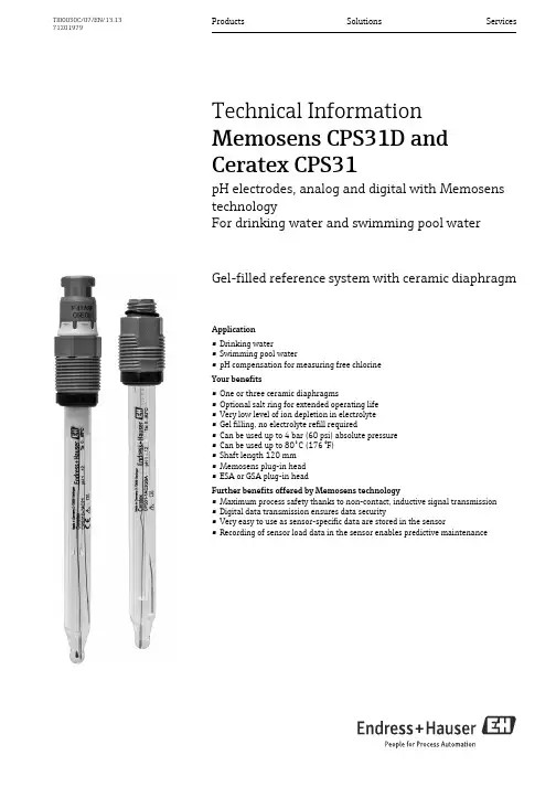
Products Solutions Services TI00030C/07/EN/13.1371201979Technical InformationMemosens CPS31D andCeratex CPS31pH electrodes, analog and digital with MemosenstechnologyFor drinking water and swimming pool waterGel-filled reference system with ceramic diaphragmApplication•Drinking water•Swimming pool water•pH compensation for measuring free chlorineYour benefits•One or three ceramic diaphragms•Optional salt ring for extended operating life•Very low level of ion depletion in electrolyte•Gel filling, no electrolyte refill required•Can be used up to 4 bar (60 psi) absolute pressure•Can be used up to 80˚C (176 °F)•Shaft length 120 mm•Memosens plug-in head•ESA or GSA plug-in headFurther benefits offered by Memosens technology•Maximum process safety thanks to non-contact, inductive signal transmission•Digital data transmission ensures data security•Very easy to use as sensor-specific data are stored in the sensor•Recording of sensor load data in the sensor enables predictive maintenanceCPS31D/CPS312Endress+HauserFunction and system designMeasuring principlepH measurementThe pH value is a measure of the acid or base character of a medium. Depending on the pH value of the medium, the electrode's membrane glass provides an electrochemical potential. This is the result of H + ions selectively penetrating the outer layer of the membrane. As a result, an electrochemical boundary layer forms here with an electric potential. An integrated Ag/AgCl reference system forms the required reference electrode.The transmitter converts the measured voltage into the corresponding pH value according to the Nernst equation.General characteristicsDurabilityDepending on the version, the electrode can withstand pressures up to 4 bar (60 psi) and temperatures up to 80˚C (176 ˚F).Communication and data processing with CPS31DMeasuring system data which digital sensors can save in the sensor include: •Manufacturer data –Serial number –Order code–Date of manufacture •Calibration data –Date of calibration–Calibrated slope at 25˚C (77 ˚F)–Calibrated zero point at 25 ˚C (77 ˚F)–Temperature offset –Number of calibrations–Serial number of the transmitter used to perform the last calibration •Operating data–Temperature application range –pH application range–Date of initial commissioning –Maximum temperature value–Operating hours at temperatures above 80 ˚C / 100 ˚C (176 ˚F / 212 ˚F)–Operating hours for very low and very high pH values (Nernst voltage below –300mV, above +300mV)–Number of sterilizations –Glass membrane impedanceThe data listed above can be displayed using the Mycom S CPM153, Liquiline M CM42 and Liquiline CM44x transmitters.Dependability with CPS31DReliabilityMemosens technology digitizes the measured values in the sensor and transmits them to thetransmitter via a non-contact connection in a way that is free from any potential interference. The result:•Automatic error message generation if the sensor fails or the connection between sensor and transmitter is interrupted•Immediate error detection increases measuring point availabilityCPS31D/CPS31Endress+Hauser 3MaintainabilitySensors with Memosens technology have integrated electronics that save calibration data and other information, such as total hours of operation and operating hours under extreme measuring conditions etc. Once the sensor has been connected, the sensor data are automatically sent to the transmitter and used to calculate the current measured value.Saving the calibration data makes it possible to calibrate and adjust the sensor irrespective of the measuring point. The result:•Convenient calibration in the measuring lab under optimum external conditions improves the quality of the calibration.•Measuring point availability is dramatically increased by the quick and easy replacement of precalibrated sensors.•The availability of the sensor data makes it possible to accurately determine the maintenance intervals of the measuring point and enables predictive maintenance.•The sensor history can be documented using external storage media and evaluation programs. The sensor's field of application can be determined based on its previous history.IntegrityWith its inductive transmission of the measured value via a non-contact plug-in connection, Memosens guarantees maximum process safety and offers the following advantages:•All problems caused by moisture are eliminated:–The plug-in connection is free from corrosion –Moisture cannot corrupt the measured value–Plug-in system can even be connected under water•The transmitter is galvanically decoupled from the medium.•EMC safety is guaranteed by screening measures in the digital measured value transmission.Measuring systemA complete measuring system comprises:•pH electrode CPS31D or CPS31•Transmitter, e.g. Liquiline CM44x (for CPS31D with Memosens technology)•Measuring cable, e.g. CYK10 for CPS31D•Immersion, flow or retractable assembly, e.g. Flowfit CCA250Example of a measuring system: pH compensation for chlorine measurement 1 Cable CYK102 Liquiline CM44x transmitter3 Chlorine sensor CCS142D4 Flowfit assembly CCA2505pH electrode CPS31DCPS31D/CPS314Endress+HauserInputMeasured variablespH value Temperature Measuring rangeInstallationInstallation instructionsDo not install the electrodes upside down. The inclination angle must be at least 15° from thehorizontal. A smaller inclination angle is not permitted as it could cause an air bubble to form in the glass sphere and prevent the inner electrolyte from completely wetting the pH membrane.Electrode installation; angle at least 15˚ from the horizontal A Permitted orientation BIncorrect orientationNOTICEBefore screwing in the electrode, make sure the threaded connection of the assembly is clean and runs smoothly.‣Hand tighten the electrode (3 Nm)! (Information valid only when installing with Endress+Hauserassemblies.)‣Also pay attention to the installation instructions provided in the Operating Instructions of theassembly used.pH:1to 12Temperature:0 to 80 ˚C (32 to 176 ˚F)CPS31D/CPS31Endress+Hauser 5EnvironmentAmbient temperature rangeRisk of damage due to frost‣The sensor must not be used at temperatures below –15 ˚C (5 ˚F).Storage temperature 0 to 50 ˚C (32 to 120 ˚F)Degree of protectionProcessProcess temperature range 0 to 80 ˚C (32 to 176 ˚F)Process pressure (absolute)1 to 4 bar (15 to 60 psi)CAUTION!Sensor is exposed to pressure when used for longer periods under increased process pressure Risk of injury due to glass breakage‣Do not apply too much heat to sensors of this type if they are being used under reduced processpressure or under atmospheric pressure.‣Wear protective goggles and suitable gloves when handling this type of sensor.Pressure-temperature loadPressure-temperature loadMinimum conductivity100 μS/cm50 μS/cm for "AC" version (three diaphragms)IP 67:GSA plug-in head (with closed connector system)IP 68:ESA plug-in head (1m (3.3 ft) water column, 50˚C (120 ˚F), 168h)IP 68:Memosens plug-in head (10 m (33 ft) water column, 25 ˚C (77 ˚F), 45 days, 1 M KCl)CPS31D/CPS316Endress+HauserMechanical constructionDesign, dimensions CPS31CPS31 with ESA plug-in head 1 ESA electrode plug-in head, Pg 13.52 Pressure ring 3 Capillaries 4 Shaft tube 5 Diaphragm6Ag/AgCl internal reference leadCPS31 with ESA plug-in head 7 pH membrane glass 8 Temperature probe 9 Internal tube 10 Leads, external 11O-ringCPS31 with GSA plug-in head 1 GSA electrode plug-in head, Pg 13.52 Pressure ring3 Compression spring4 Capillaries5 Diaphragm6Ag/AgCl internal reference leadCPS31 with GSA plug-in head 7 pH membrane glass 8 Internal tube 9 Shaft tube 10 Lead, external 11 O-ringCPS31D/CPS31Endress+Hauser 7Design, dimensions CPS31DWeight 0.1 kg (0.22 lbs)MaterialsProcess connection Pg 13.5Temperature sensorPlug-in headsReference systemAg/AgCl, gel, 3M KClOptional: Salt ring, KCl-saturatedCPS31D 1 Memosens plug-in head 2 Pressure ring 3 Lead, external 4 Capillaries5 Salt rings (optional)6DiaphragmCPS31D 7 Ag/AgCl internal reference lead 8 pH membrane glass 9 Temperature probe 10 Shaft tube11 Internal tube with leads 12O-ringElectrode shaftGlass pH membrane glass Type A Metal lead Ag/AgCl Diaphragm CeramicCPS31D:NTC 30K CPS31:Pt 100CPS31D:Memosens plug-in head for digital, non-contact data transmission CPS31:ESA, GSACPS31D/CPS318Endress+HauserCertificates and approvalsTÜV certificate ESA and Memosens plug-in head Pressure resistance 16 bar (232 psi), minimum three times the safety pressureElectromagneticcompatibility of CPS31DInterference emission and interference immunity as per EN 61326: 2006Ordering informationProduct pagesYou can create a valid and complete order code on the Internet with the Configurator tool.Enter the following addresses in the browser to access the relevant product page://cps31dProduct Configurator1.2.Click "Configure this product".3.The Configurator opens in a separate window. You can now configure your device and receive the complete and valid order code.4.Now export the order code as a PDF or Excel file. To do so, click the corresponding button at the top of the page.CPS31D/CPS31Endress+Hauser 9AccessoriesAssemblies (selection)Cleanfit CPA472•Compact plastic retractable assembly for installation in tanks and pipes, for manual or pneumatically remote-controlled operation•Order according to product structure (--> Online Configurator, /cpa472)•Technical Information TI00223C/07/ENCleanfit CPA475•Retractable assembly for installation in tanks and pipes under sterile conditions•Order according to product structure (--> Online Configurator, /cpa475)•Technical Information TI00240/C/07/ENUnifit CPA442•Installation assembly for food, biotechnology and pharmaceutics, with EHEDG and 3A certificate,•Order according to product structure (--> Online Configurator, /cpa442)•Technical Information TI00306/C/07/ENDipfit CPA111•Immersion and installation assembly for open and closed containers•Order according to product structure (--> Online Configurator, /cpa111)•Technical Information TI00112C/07/ENFlowfit CPA250•Flow assembly for pipe installation of pH/ORP sensors with Pg 13.5 and 120mm (4.72") installation length•Order according to product structure (--> Online Configurator, /cpa250)•Technical Information TI00041C/07/ENEcofit CPA640•Adapter for 120mm pH sensors•Order according to product structure (--> Online Configurator, /cpa640)•Technical Information TI00264C/07/ENBuffer solutionsHigh quality buffer solutions of Endress+Hauser - CPY20Solutions which are traced by a DAkkS-accredited Endress+Hauser buffer laboratory (DkkS = German Accreditation Body) to a primary reference material of the PTB and to standard reference material of the National Institute of Standards and Technology (NIST) in accordance with DIN 19266 are used as secondary reference buffer solutions.•Order according to product structure (-> Online Configurator, /cpy20)Measuring cableMemosens data cable CYK10•For digital sensors with Memosens technology•Order according to product structure (--> Online Configurator, /cyk10)•Technical Information TI00118C/07/ENMeasuring cable CPK9•For sensors with ESA plug-in head, for high-temperature and high-pressure applications, IP 68•Order as per product structure•Technical Information TI00501C/07/EN Special measuring cable CPK1•For pH/ORP electrodes with GSA plug-in head •Order as per product structure• Technical Information TI00501C/07/EN。
全站仪(日本索佳30系)操作说明(中文)
电子全站仪(30系列)操作手册适用型号:SET230R/R3 SET330R/R3 SET530R/R3 SET630R一、注意事项(2)1.第一次使用仪器前,应松开底座开关钮上的紧固螺母;2.禁止带三脚架一起搬动仪器;3.取电池前一定要关断电源;4.激光束不能对着人,有害,更不能从目镜去看;5.仪器每天用完入箱前,应取出电池。
`二、基本操作(5)1.基本键操作(5.1)·开关电源按{ON}:电源开;按住{ON}再按{灯}:电源关。
·开关屏幕按{灯},屏幕背景灯亮灭;按住{灯}直到滴滴响声,开关激光束。
·软键操作(软键指在屏幕内底部的键)按{F1}-{F4},选择需要的软键;{FUNC}键用于在测量方式[MEAS]状态下的屏幕翻页(当多于4个软键时);·输入字母和数字{F1}-{F4}:输入分布在软键上的数字和字母;{FUNC}:翻页找你需要的字母、数字;(按住一会儿)回上页;连续按,往前翻。
{BS}:删除左侧字母数字;{ESC}:取消输入数据;{SFT}:选择的接收靶类型显示;{←}:(回车)接受输入的数据。
·选择键{▲}/{▼}:光标上下移动;{<}{>}:左右移动光标/其它选择;{←}: 确认选择;·模式转换[CNFG]:(软键)从主屏模式到设置(Configuration)模式;[MEAS]:从主屏模式到测量(Measure)模式;[MEM]:从主屏模式到内存存储(Memory)模式;{ESC}:从各状态返回到主屏状态。
·其它操作{ESC}:返回上一屏。
2.屏幕功能距离:S:斜距;H:水平距;V:参考高度;竖向角度:ZA:天顶角(Z=0);VA:竖向角(H=0/H=±90);水平角度:按[R/L]转换状态:HAR:水平右转;HAL:水平左传;按[◢SHV],转换“S,ZA,H”,到“S,H,V”。
3.开机程序(9)开机后,仪器自检。
SDC36操作设定--简易版
SDC36设定操作步骤一台新SDC36在首次应用时按照如下的方式设定参数,如仪表已经设定有内容(其他现场使用过)请先恢复出厂设定(方法是:使用SLP-C36软件)。
一、仪表参数设定1。
进行组态参数设定:仪表上电后,应在基本运行显示态;即上行显示PV:XXXX下行显示SP:XXXX如在其它状态,按Display键,使仪表回到基本运行显示状态。
此时按住para键2秒钟以上,仪表上行显示ModE闪烁,继续按动para键(短按)多次,仪表上行显示依次出现SP、PID、PArA、StUP、EvCF、dI、dO、LoC、ID等数据库名,到仪表上行显示StUP时,按enter键进入设定功能库,仪表上行显示C01,进行设定功能设定。
①设定输入类型:如输入为S型热电偶,设定C01=16;(S型热电偶,测量范围0~1600℃)如输入为K型热电偶,设定C01=2;(K型热电偶,测量范围0~1200℃)在仪表上行显示C01时,按enter改为要设定的数值(16或2),按enter键数值闪烁停止,修改被确认②设定设定值上限:设定C08=上限设定值(方法略)③设定目标值数量(有几个保温段):设定C30=目标值数量(即有几个保温段设定为几,方法略)④设定斜坡类型:设定C31=2⑤设定升温(降温)速度单位设定C32=1(升温速度为:X ℃/分)C32=2(升温速度为:X ℃/小时)⑥设定保温时间的时间单位设定C33=1(保温段保温时间的时间单位为:秒)C33=2(保温段保温时间的时间单位为:分)⑦设定启动方式:PV启动设定C34=1(启动方式为升温PV启动,即从当前PV值按升温速度升温至第一个目标温度值)⑧设定步运行停止方式:设定C35=0(温度曲线运行到终点后停止输出)设定C35=2(温度曲线运行到终点后长期保持在最后的目标值上)以上设定结束后,按display键回基本运行显示状态。
2。
事件功能设定设定EV1的功能为温度上限报警。
SDC安全门控系统产品说明书
SDC’s patented EMLock® design represents the pinnacle of mag-netic lock evolution. The modular EMLock® assembly makes them easy to stock, install, upgrade and maintain.SDC 1500 series EMLocks® include a lifetime warranty and are available in 650lbs, 1200lbs, and 1650lbs holding force. Compatible with any access control system, all EmLocks® are adaptable to virtually any application utilizing Top Jamb or Glass Door mounting kits. The epoxy-less design provides a superior appearance with a plated or anodized finish on allsides. The interlocking EZ mount assembly leaves hands free for wiring and securing of mounting screws. EMLocks® are UL Listed and ANSI Grade 1 compliant.1500 SeriesEMLock®FEATURES• Modular Design • Modular Upgrade Kits • Field Upgradeable withoutremoving from the frame• Uniform Design &Installation• Identical Housing, Template& Accessories• Quick Mount AssemblySTANDARD MOUNTING FASTENERS Self Drilling & Tapping Sheet Metal Screws and 10/32 Machine Screws supplied for different application needs. Blind nuts and Tool are op-tional.UPGRADE MODULES INCLUDE:• Relock Delay Timer • Magnetic Bond Sensor • Door Status Sensors • Anti-Tamper SwitchSecurity Door ControlsSECURITY DOOR CONTROLS ACCESS & EGRESS SOLUTIONS - THE LOCK BEHIND THE SYSTEM21510 SERIES GRADE 11650 LB / 748 KG HOLDING FORCE1570 SERIES GRADE 11200 LB / 544 KG HOLDING FORCE 3 WATTS ENERGY SAVER1580 SERIES GRADE 1650 LB / 295 KG HOLDING FORCESPECIFICATIONSVoltage 12/24VDC Voltage Sensing InputSingle350mA @ 24VDC; 670mA @ 12VDC11” L x 2-3/4” H x 1-9/16” D Double700mA @ 24VDC; 1.34A @12VDC22” L x 2-3/4” H x 1-9/16” DSPECIFICATIONSVoltage 12/24VDC Voltage Sensing InputSingle125mA @ 24VDC; 250mA @ 12VDC11”L x 2-3/4”H x 1-9/16”DDouble 250mA @ 24VDC;500mA @ 12VDC22” L x 2-3/4” H x 1-9/16” DSPECIFICATIONSVoltage 12/24VDC Voltage Sensing InputSingle220mA @ 24VDC; 440mA @ 12VDC8-3/4”L x 2-1/8”H x 1-1/4”D Double440mA @ 24VDC; 880mA @ 12VDC17-1/2” L x 2-1/8” H x 1-1/4”D15821581151315121511UL Listed U.S. & Canada: GWXT Auxiliary LocksCVXJ Burglary Resistant Electrically Operate-Door LockUL10C: Position Positive Pressure CompliantUBC: Classified in accordance with Uniform Building Code standard 7-2 “Fire Test for Door Assemblies”ANSI/BHMA A156.23: Grade 1, one million cycles BHMA CertifiedCSFM: California State Fire Marshal Listed 3774-0324:100MEA: City of New York 61-95-E157315721571LISTINGS & PERFORMANCE SPECIFICATIONS1511 Single EMLock®1512 Double EMLock®1513 Single, split armature for pair of doors1571 Single EMLock®1572 Double EMLock®1573 Single, split armature for pair of doors1581 Single EMLock®1582 Double EMLock®MODELSFIELD INSTALLED OPTION KITS Ordered separately for field upgrade. For complete details contact SDC to request more information on Modular Upgrade Kits.EZ-T-10 Adjustable Timer InputModule: Specify (1) for single or double EmLocks®(not available with 1580 series) EZ-D-10 1510, 1570 Door Position Sensor Module: Specify (2) for double EMLocks®(not available with 1513 and 1573) EZ-D-80 1580 Door Position Sensor Module: Specify (2) for double EM-Locks®EZ-B-10 1510, 1570 Magnetic Bond Sensor Module: Specify (2) for double EMLocks®(Not available with 1513,1573) EZ-B-80 1580 Magnetic Bond Sensor Module: Specify (2) for double EM-Locks®EZ-A Anti-Tamper Switch Module: Indicates cover plate removal.EZ-1510W Holding Force Module: Ex-change a 1200lb wire coil (1570 series) with this 1650lb wire coil.Specify (2) for double EMLocks® EZ-1570W Energy Saver Module: Save on power supply and long term energy costs by exchanging 8.4 Watt, 1650lb coil with 3 Watt, 1200lb hold-ing force coil. Specify (2) for double EMLocks®All available throughACCESSORIESSpecify housings with your EMLocks ®. Example : 1511V-30; 1512V-60DC-2DC-1Anodized FinishesV Aluminum (standard) Y Black anodizedPainted FinishesC Brass powder coat X Dark bronze powder coat Plated Finishes (special order)P Bright chrome Q Dull chromeFEATURESVertical Housings - Side jamb mount, providing 2400 or 3300 lbs of holding force.FINISHACCESSORIESPRE-DRILLED & TAPPED HEADER BRACKETMachined Wire ChaseHoles Pre-Drilled & Countersunk For Frame MountingPre-Drilled and TappedLock Mounting HolesUF81VUF11VAluminum frames with blade stop - lowers EmLock below blade stop. Concrete filled hollow metal frames provides multiple points for concealed wire entry• Pre-drilled and tapped specifically for 1511, 1571, 1581 EmLock • Machined wire chase provides multiple points for concealed wireentry from concrete filled frames.• 628 Aluminum AnodizedFEATURESUsed in lieu of angle brackets, the Universal Header Bracket provides a faster mounting solution, saving time and labor costs for several EmLock models. Reduce potential for mis-sized and misaligned mounting holes, broken taps, removal of broken taps. Combined with interlocking. E-Z mount assembly, save up to a half days labor with the instal-lation of 12 locks.• Solid 1” bar provides higher security and superior aesthetics.• Machined wire chase provides concealed and secure wiring• Multiple pre-drilled and tapped mounting holes to accommodate theuse of several different locks on either 4” or 4.5” aluminum framesFEATURESFINISHV 628 Aluminum (standard)C 605 Bright BrassD 606 Dull BrassP 625 Bright Chrome Q 626 Dull Chrome X 313 Dark Bronze Y 335 BlackSecurity Door ControlsSECURITY DOOR CONTROLS ACCESS & EGRESS SOLUTIONS - THE LOCK BEHIND THE SYSTEM659mm51mm2"BA2 5/16"FILLER PLATESFor 22” (559mm) Double Emlock Models 1512 / 1572PART # A x BFP21 1/8” x 1-1/4” FP22 1/4” x 1-1/4” FP23 3/8” x 1-1/4” FP24 1/2” x 1-1/4” FP255/8” x 1-1/4”For 17-1/2” (445mm) Double Emlock Model 1582PART # A x BFP30 1/8” x 1-1/4” FP31 1/4” x 1-1/4” FP32 3/8” x 1-1/4” FP33 1/2” x 1-1/4” FP34 5/8” x 1-1/4”For 10”-11” Single Emlock & Exit CheckModels 1511, 1513, 1571, 15731511S, 1511T, 1511DEV, 1571DEV PART # A x B FP11 1/8” x 1-1/4” FP12 1/4” x 1-1/4” FP13 3/8” x 1-1/4” FP14 1/2” x 1-1/4” FP155/8” x 1-1/4”For 8-3/4” Single Emlock & Exit Check Models 1581, 1581DEPART # A x B FP01 1/8” x 1-1/4” FP02 1/4” x 1-1/4” FP03 3/8” x 1-1/4” FP04 1/2” x 1-1/4” FP05 5/8” x 1-1/4”2"2 5/16"59mm51mmGlass DoorTop RailGlassARMATURE MOUNTING PLATEAR11Y Armature mounting plate for 1511, 1571335 Black Anodized (Specify two for models 1512, 1572)AR11YD A rmature mounting plate with DPS for 1511, 1571.335 Black Anodized(Specify two for models 1512, 1572)The AR Mounting plate provides a solution for mounting the EMLock® armature to the top rail of herculite, aluminum and glass, wood and hollow metal doors that do not permit the use of thru bolts.APPLICATIONMODELSMODELSAPPLICATIONFor extension of the stop to provide a proper mounting surface on the underside of the header See Figure 1B.ANGLE BRACKETSREUSABLE HEAVY DUTYDRILL FIXTUREBLIND NUTPLACEMENT TOOLINTERLOCKING QUICK MOUNT ASSEMBLY1511-DF1581-DFadequate mounting surface. See Figure 1C.© 2018 SECURITY DOOR CONTROLS Security Door ControlsLIT-EMLOCK-BROCHURE 04/18[t] 800.413.8783 805.494.0622 [f] 866.215.3138 801 Avenida Acaso, Camarillo, CA 93012 PO Box 3670, Camarillo, CA 93011TYPICAL DOOR APPLICATIONS1511 1571 1581• AB Angle bracket • Aluminum frame• Aluminum & glass door • Push side mounting 1511-HDB1 1571-HDB11581-HDB1• Glass door mounting kit • AB series angle brackets • Metal or aluminum frame • Glass door w/o top rail • Push side mounting 1511-(36) 1571-(36)• Full width architecturalhousing• Specify length(30”, 36”, 40”, 48”)• Aluminum frame• Aluminum & glass door • Push side mounting 1511 1571 1581• Hollow metal frame • Wood/hollow metaldoor• Push side mounting1511-TJ1 1571-TJ11581-TJ81• Top jamb mounting kit • Hollow metal frame• Wood or hollow metal door • Pull side mounting 1512 1572 1582• AB Angle bracket • Aluminum frame• Aluminum & glass doors • Push side mounting1513 1573• Split armature• Hollow metal frame • Wood or hollowmetal doors• Push side mounting1512 1572 1582• Hollow metal frame • Wood or hollow metaldoors• Push side mounting1512-HDB2 1572-HDB21582-HDB2• HDB Glass door mountingkit• AB series angle bracket • Metal or aluminum frame • Glass door without top rail • Push side mountingCOMMUNICATING BATHROOM EMLOCKS®Single hospital bathroom shared by two patient rooms.SYSTEM OPERATIONBoth doors must be closed to lock.Activating CB401A (B) locks both doors.Activating CB401A (B) again unlocks both doors.When doors are locked, activating either CB401B (C) emergency release will unlock both doors.Both doors will unlock automatically via signal from fire panel.SYSTEM COMPONENTS (A)Fail Safe locks with door position switch. Example: 1511-DPS(B) CB401A System activation push switch.(C)CB401B Emergency release push switch to be mounted above each door. CB701B key switch optional.(D)631RF-UR1 Power Supply with Fire Panel Tie-In and Communicating Bath ControllerFROM FIRE PANEL 110 VAC INPUTPOWER SUPPYAABCC D。
TC31A 用户手册
宝力机械公司PRO-TECHNIC MACHINERY LTD. 日本『兄弟』数控攻牙中心TC31A用户保养手册宝力机械EDM组着序问题:您有做机床保养吗?答:会。
问:您知道如河正确地做机床保养吗?答:悟……很多用户认为机床的保养是非常简单的事,只要定期做清洁及打油便可,跟本不用多说,亦不必长篇大论。
然而,我们宝力公司却有不同的观点,我们认为机床维护是一项非常重要,不容马虎的工作。
做得安全、正确、有系统、有质量,才能使机床发挥最高的效能、最高的生产质量、以及最长的寿命。
反之,做得不正确,则弄朽反拙。
易生危险。
作为机床的代理商,客户的信任者,我们有责任提供专业的机床保养技术,让我们尊敬的客户正确地定期维护他的生财工具,减少故故障的发生。
故特别篇辑这份中文手册,给有关的机床管理人员使用。
不尽之处,请参阅英文INSTALLATION MANUAL。
EDM SECTION SUPERVISOR12-1999目录第一章机床基本结构简介第二章使用机床的注意事项第三章机床定期检查保养第四章机床调整点第五章外部连接第六章 故障排除第七章 加工资料第八章 警报表第一章机床基本结构简介1-1机床主要配件名称1-1-1机床配件1-1-2电控箱配件1-2 机械结构简介1-2-1主轴1-2-2 XYZ走轴1-2-3 ATC自动换刀装置1-2-4 C轴转台1-1机床主要配件名称1机床配件编号名称1 电控箱Control box2 防水罩Splash guard5 保护门生效掣Door interlock switch8 保护门锁匙Door interlock key9 主轴Spindle10 自动换刀库ATC magazine13 调水平螺丝Level bolt14 切屑液喷管Coolant nozzle15 刀库盖板Magazine cover16 刀具Tooling17 刀柄Tool holder18 主轴头Spindle head19 急停开关Emergency stop switch20 旋转工作台Turn table21 电源总开关/跳闸Main power breaker22 切削液箱Coolant tank23 防水侧盖板Splash guard side cover24 马达电阻器Regenerative resistor cover25 操作面板Operation panel27 装刀架Tool pot28 气压调整表板Pressure gauge29 切削液马达Coolant pump30 主轴马达Spindle motor31 刀臂马达Cam motor32 刀库马达Magazine motor33 拉钉Pull stud34 旋转刀臂Turn arm assy.35 刀爪Finger1-1-2电控箱配件编号名称36 马达驱动器X,Y,Z,S,MAG,C driver37 主电路板,NC PCB,38 输出/入电路板I/O PCB39 直流自动稳压器AVR1-2机械结构简介1-2-1主轴1) 使用高精度轴承,可长时间高速转动中仍能保持顺畅。
- 1、下载文档前请自行甄别文档内容的完整性,平台不提供额外的编辑、内容补充、找答案等附加服务。
- 2、"仅部分预览"的文档,不可在线预览部分如存在完整性等问题,可反馈申请退款(可完整预览的文档不适用该条件!)。
- 3、如文档侵犯您的权益,请联系客服反馈,我们会尽快为您处理(人工客服工作时间:9:00-18:30)。
˙ 盤開孔圖
ɾɾɾɾɾɾɾɾɾɾɾɾɾɾɾɾɾɾɾɾɾɾɾɾɾɾɾɾɾɾɾɾɾɾɾɾɾ
4%$ ɾɾɾɾɾɾɾɾɾɾɾɾɾɾɾɾɾɾɾɾɾɾɾɾɾɾɾɾɾɾɾɾɾɾɾɾɾɾɾɾɾɾɾɾɾ
˙ 外形尺寸圖 ɾɾɾɾɾɾɾɾɾɾɾɾɾɾɾɾɾɾɾɾɾɾɾɾɾɾɾɾɾɾɾɾɾɾɾɾɾɾɾɾ
DIGITRONIC 3 是株式會社山武的注册商標。
2004 Yamatake Corporation ALL RIGHTS RESERVED
҆શཁ ߲ࣄٻ4"'&5:3&26*3&.&/5
爲了减少對人體造成傷害的觸電危險,請遵守本使用説明書記載的所有與 安全相關的注意事項。 本符號是表示觸摸後有觸電的危險,向用戶作警示用。
.0%&
-0"%&3 &/5
硬防塵蓋套(另賣)
˙ 盤開孔圖
˔ 盤開孔尺寸
ʷ
ʷ
硬防塵蓋套(另賣)
安裝件81405411-001
୯Ґ NN
୯ҐNN
端子螺絲M3.5
୯ҐNN
ᶍ 編程器連接口 :手持設定器(另賣)接続用的連接口。
使用上的注意事項
不能用鉛筆或螺絲刀的尖部觸及本機的操作鍵。 否則可能會産生故障。
ୈ ষ 外形尺寸
4%$
˙ 外形尺寸圖
硬防塵蓋套(另賣)
17
41 065
%*41
0,3&"%:
41&7 6'
˛
˛ ˛
˛ ˛
ᶃ 第一顯示部 :通常PV(Process Variable)顯示。 參數等顯示的場合,將顯示其項目。
ᶄ 第二顯示部 :SP(Set Point)顯示。 參數等顯示的場合,將顯示其內容。
ᶅ 模式LED SP/OUT :表示第二顯示部顯示的內容。 SP燈亮 :SP顯示中。 OUT燈亮 :MV(操作量)顯示中。 SP.OUT燈滅 :電機開度顯示中。 同時如下記所示顯示「SP斜坡動作中」、「手動狀態」。 SP閃爍 :表示SP斜坡動作中。 OUT閃爍 :表示手動狀態。 EV1~EV2 :事件輸出輸出爲ON時燈亮。 CLS(僅2G) :閉方向繼電器ON時燈亮。 OPN(僅2G) :開方向繼電器ON時燈亮。 OT(2G以外) :繼電器輸出(0D)繼電器ON時燈亮、繼電器OFF時燈滅。 電壓輸出(6D) 電壓輸出狀態時燈亮、未輸出狀態時燈滅。 電流輸出(5G) 常時燈亮。 REM :遠程設定輸入(RSP)選択時燈亮。 AT :自整定動作中時閃爍。 超調抑制控制學習中時燈亮。
Փ⫼Ϟⱘ䰤ࠊ
ᴀ⫷કᰃՓ⫼ϔ㠀䀁ᦤࠡ٭ϟ䘆㸠䭟ⱐǃ䀁㿜ǃ㻑䗴ⱘDŽ᳝ϟ߫ᅝܼ
ᗻ㽕∖ⱘจড়Փ⫼ᰖˈ䂟џᬙֱܼ䀁㿜ˈݫ们䀁㿜ঞᅮᳳ㎁䅋 Ẕᶹҹঞᇡ㋏㍅ঞ䀁٭ᭈ储ㄝ㗗ᝂ਼ܼⱘᚙ⊕ϟՓ⫼DŽ ҹҎ储ֱ䅋⠆Ⳃⱘⱘᅝܼ㺱㕂 䔌䗕䀁 ࠊⳈⱘ٭䘟㸠ذℶㄝ
㟾ぎ䀁٭
ᅛᅭ䀁٭ 原子能设备等 䂟ϡ㽕ᡞ䁆⫷ક⫼ᮐ㟛⫳ੑⳈⳌ䮰ⱘ⫼䗨ϞDŽ
要∖
䂟⺎ֱᡞᴀՓ⫼䁾ᯢ䗕ࠄᴀ⫷કՓ⫼㗙ЁDŽ 火ℶ᪙㞾㻛ॄܼ䚼䚼ߚᴀՓ⫼䁾ᯢˈ火ℶ䔝䓝ᴀՓ⫼ 䁾ᯢDŽҞᕠܻᆍ䅞ᰖᘩϡџܜ䗮ⶹDŽ ᴀՓ⫼䁾ᯢⱘܻᆍˈ㍧䘢Ҩ㌄ᆽᶹ᷵ᇡˈ㨀ϔ᳝䤃䁸 䙎ⓣˈ䂟ᴀ݀ৌᦤߎDŽ ᇡᅶ᠊ឝ⫼㌤ᵰˈᴀ݀ৌ᳝ϡ㛑ᡓ᪨䊀ӏⱘจড়ˈ䂟䂦㾷DŽ
˙ 輸出値顯示
ɾɾɾɾɾɾɾɾɾɾɾɾɾɾɾɾɾɾɾɾɾɾɾɾɾɾɾɾɾɾɾɾɾɾɾ
˙ 電機開度顯示(位置比例輸出)
ɾɾɾɾɾɾɾɾɾɾɾɾɾɾɾɾɾɾɾɾɾɾɾ
˙ SP 變更(單SP 的場合) ɾɾ ɾ ɾ ɾ ɾ ɾ ɾ ɾ ɾ ɾ ɾ ɾ ɾ ɾ ɾ ɾ ɾ ɾ ɾ ɾ ɾ ɾ ɾ ɾ ɾ
請不要把綫頭、水、鐵屑等防入本機殼體內部。 有火灾、故障的可能。 本機電流輸入端子⑥、⑧的輸入,請在規格記載的電流、電壓範圍內使用。 有火灾、故障的可能。
請按規格中規定的扭矩充分擰緊端子螺絲。 螺絲擰緊不充分時,有觸電、火灾的危險。 請不要把本機未使用的端子作爲中継端子使用。 有火灾、觸電、故障的可能. 本機接綫後,建議安裝上端子蓋。 有觸電的危險。(本機備有另賣的端子蓋) 請在規格中記載的壽命範圍內使用本機的繼電器。 超過壽命繼續使用時,有故障、火灾的危險。 有發生雷擊可能的場合,請使用本公司的浪涌吸收器。 有火灾、故障的可能。
˙ SP 變更(單SP 的場合) ɾ ɾ ɾ ɾ ɾ ɾ ɾ ɾ ɾ ɾ ɾ ɾ ɾ
˙ 選擇SP後改變其設定値(多SP 的場合)
ɾɾɾɾɾɾɾɾɾɾɾɾɾɾɾɾɾ
˙ 自動/手動的模式変更方法
ɾɾɾɾɾɾɾɾɾɾɾɾɾɾɾɾɾɾɾɾɾɾɾ
˙ RUN/READY的模式変更方 法 ɾ ɾ ɾ ɾ ɾ ɾ ɾ ɾ ɾ ɾ ɾ ɾ ɾ ɾ ɾ ɾ ɾ ɾ ɾ ɾ ɾ ɾ ɾ ɾɾ
使用上的注意事項
本機的電源投入後,爲了使機器穩定,在最大7秒鐘內將不起作用。
JJ
目錄
安全要求事項 安全上的注意
ୈ ষ 各部的名稱及功能
ୈ ষ 外形尺寸
4%$ ɾɾɾɾɾɾɾɾɾɾɾɾɾɾɾɾɾɾɾɾɾɾɾɾɾɾɾɾɾɾɾɾɾɾɾɾɾɾɾɾɾɾɾɾɾ
˙ 外形尺寸圖 ɾɾɾɾɾɾɾɾɾɾɾɾɾɾɾɾɾɾɾɾɾɾɾɾɾɾɾɾɾɾɾɾɾɾɾɾɾɾɾɾ
JW
ୈ ষ 各部的名稱及功能
ᶅ模式LED ᶆ綠帶 ᶈ41&76'鍵 ᶉ.0%&鍵
4%$ ʷ尺寸
17
41 065
&7 &7 $-4 01/ 3&. "5 %*41
0,3&"%:
41&7 6'
.0%&
-0"%&3 &/5
ᶊ&/5鍵
ᶃ第一顯示部 ᶄ第二顯示部
ᶇ%*41鍵 ᶋ上升 鍵 ᶌ下降 鍵 ᶍ編程器連接口
請不要觸摸電源端子等的受電部。 有觸電的危險。 請不要分解本機。 有觸電、故障的可能。
ҙ
請在規格中記載的使用條件(溫度、濕度、電壓、振動、衝撃、安裝方向、 環境等)的範圍內使用本機。 有火灾、故障的可能。 請不要蓋住本機的通風孔。 請不要蓋住本機的通風孔。 請按規定的基準、指定的電源及施工方法進行本機的正確接綫。 有火灾、觸電、故障的可能.
ɾ 請不要用本公司規定之外的部品進行部件更換。 ɾ 所有的配綫作業,必須請按當地的規定,由具有経験的作業者進行。
ɾ GND端子的配綫務必在其他配綫前進行。 ɾ 在儀錶操作者手能觸及的範圍內,請務必設置本産品用的主電源切斷開關。 ɾ AC電源型的主電源配線中,請設置遅動型(T)的額定值電流爲0.5A、額定電壓爲250V的保險絲。
ᶉ MODE鍵 :自整定的起動/停止、自動/手動、運行/待機、選擇LSP/RSP的模式変更項目。
ᶊ ENT鍵 :確認変更的數値。把顯示的參數等項目變爲置換(変更)狀態。
ᶋ UP ˛ 鍵 :増加數値。顯示中的參數等項目的順次切換。
ᶌ DOWN 鍵 :减少數値。顯示中的參數等項目的順次切換。
*&$
機器的額定值 供給電壓 :100~240V AC(動作電源電壓:85~264V AC) 電源頻率 :50/60Hz 消耗功率 :18VA Max.
ڥ݅ ɾ 請不要在有可燃性液體或蒸気存在的場所使用。在這樣的環境下使用時,會損壞安全性。
ᶆ 綠帶 :PV(測定値)與SP(設定値)之差(偏差)處于由設定項目C43設定的範 囲內時燈亮。另外READY狀態時閃爍。
ᶇ DISP鍵 :把顯示回到基本顯示。 第一顯示部上PV、第二顯示部上SP顯示。另外、第二顯示部的顯示內容切換。
ᶈ SP/EV/UF鍵 :選擇SP、事件及本鍵中登録參數設定値的置換可能狀態。
˙ 鍵操作概略 ɾɾɾɾɾɾɾɾɾɾɾɾɾɾɾɾɾɾɾɾɾɾɾɾɾɾɾɾɾɾɾɾɾɾɾɾɾɾ
˙ PV 顯示 ɾ ɾ ɾ ɾ ɾ ɾ ɾ ɾ ɾ ɾ ɾ ɾ ɾ ɾ ɾ ɾ ɾ ɾ ɾ ɾ ɾ ɾ ɾ ɾ ɾ ɾ ɾ ɾ ɾ ɾ ɾ ɾ ɾ ɾ ɾ ɾ ɾ
˙ SP 顯示 ɾɾ ɾ ɾ ɾ ɾ ɾ ɾ ɾ ɾ ɾ ɾ ɾ ɾ ɾ ɾ ɾ ɾ ɾ ɾ ɾ ɾ ɾ ɾ ɾ ɾ ɾ ɾ ɾ ɾ ɾ ɾ ɾ ɾ ɾ ɾ ɾ
DIGITRONIC 數字指示調節器
4%$
使用説明書
操作手册
/P$141$
非常感謝您購買本公司數字指示調節器 SDC30/31,本使用說明書中記載了正確使 用SDC30/31的必要事項。 使用SDC30/31進行控制盤、裝置設計及維 護的人員務必在閱讀幷理解本書的基礎上 使用該産品。本書不僅在安裝時使用,在 維護及處理故障時也使用。(LSP)/遠程SP(RSP)的模式変 更 方 法 ɾɾɾɾɾɾɾɾɾɾɾ
˙ 自整定的起動/停止方法
ɾ ɾ ɾ ɾ ɾ ɾ ɾ ɾ ɾ ɾ ɾ ɾ ɾ ɾ ɾ ɾ ɾ ɾ ɾ ɾ ɾ ɾ ɾ
ୈ ষ 故障處理
˙ 報警的顯示 ɾɾɾɾɾɾɾɾɾɾɾɾɾɾɾɾɾɾɾɾɾɾɾɾɾɾɾɾɾɾɾɾɾɾ
༻Թൣғ
ɿʙˆ
༻࣪ൣғ
ɿʙ3)
ڐ༰ৼಈ
ɿ NT ʙ )[
過電壓歸類 ɿ$BUFHPSZᶘ *&$ *&$
Ԛછ
ɿ1PMMVUJPOEFHSFF
機器的設置
ɾ 請使用者不要觸摸機器的背面端子,本産品必須進行儀錶盤安裝。
ᶅ模式LED ᶆ綠帶 ᶈ41&76'鍵
ᶉ.0%&鍵
4%$ ʷ尺寸
17
41 065
&7 &7 $-4 01/ 3&. "5 0,3&"%: