意大利彗星隔膜泵说明书
意大利艾格尔气动隔膜泵MPP100操作使用说明书

操作 & 维修手册气动双隔膜泵操作手册感谢您选购我公司最经久耐用、功能强大的气动隔膜泵产品。
正确的安装和维护可极大地提高泵的性能并延长泵的使用寿命。
安装和操作泵之前,请阅读下列警告及安全措施。
不遵守这些指南会危及人和财产。
请保管好该操作指南以备将来查询。
警告使用前,请确定泵是否耐介质的腐蚀。
温度、浓度和化学成分的变化,会改变材料的耐腐蚀性。
使用前,请查询材料的安全数据表和化学耐腐蚀性能表。
请确认此设备操作者接受过安全操作程序培训。
危险泵送危险或有毒液体,必须要佩戴防护眼镜及防护服:z如膜片破裂,所泵送的物料可能会进入泵空气侧,并通过消音器排出时,当泵送危险液体时,排气口须远离工作区域和人。
z当物料的液位高于泵的水平位置时(自灌入吸面),应把排气口用管路引出到高于物料液位的高度,从而防止当膜片破裂时液体由于虹吸作用引起喷溅。
危险带压危险:系统带压时,不要清洗或维护泵、管或分配阀,否则会造成严重损害。
z拆卸前,请泄压并拆除供气管线。
危险静电警告:使用非导电版的泵输送易燃物料可能会形成静电。
静电火花可能引起爆炸,并导致人员伤亡。
输送易燃物体或泵在易自燃的环境下使用,请将泵及泵送系统接地。
当泵需接地线时,我们有多种型号的导电版非金属泵可供选择。
请用接地线并确保连接到接地良好的接地端子上。
z固定泵,连接所有接触点,避免震动及产生接触性或静电火花。
有必要定期用欧姆表测量各部件对地的电通性。
z特殊的接地连接,请查询地方建筑规范和电气规程。
z使用带电丝的软管。
z使用正确的通风系统。
z易燃物要远离热源、明火、火花。
z不用时,请密封保存。
警告最高温度只取决于机械应力。
一些化学制品会极大地降低最大安全操作温度。
请咨询工程指导,了解化学防腐性能及温度极限。
z输送高温液体时,一定要用最小供气压力。
警告供气压力过高,会造成泵损毁,人身伤害,财产损失。
警告经过维修保养的泵,重新组装时,一定要正确组装。
注意不能用泵作管道系统的支撑。
Pulsafeeder机械隔膜计量泵说明书
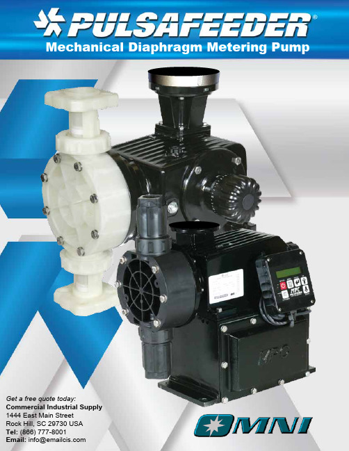
Get a free quote today:Commercial Industrial Supply 1444 East Main StreetRock Hill, SC 29730 USA Tel: (866) 777-8001Email: *****************Pulsafeeder ExpertiseSince 1936, Pulsafeeder has been the global leader in fluids handling technology and innovation in chemical dosing. Pulsafeeder has built a foundation of success with thousands of installations in fluid handling applications. Our extensive product breadth enables us to provide the convenience and efficiency of single-source solutions across various industries. 0912123135221008360002456831382669510.03.04.05.16.210.3180047675.7860160046.265.8175249435200114.9227.2422.710.36.25.13200845J K22 (5.8) 14 (3.8) 44(11.6) 28(7.5)75.7(20)49(13.0)102 (26.9) 66 (17.4)175 (46.2)113(30)128 (33.8) 83 (21.9)195 (51.5) 126 (33.4)249 (65.8) 161 (42.7)1300 (343) 843(222.6)1600 (423) 1037 (274.0)2600 (687) 1686 (445.3)3200 (845) 2074 (548.0)10.3 15010.3 15010.3 150 5.1 75 5.1 7510.3 15010.3 15010.3 150 4 60 4 60 4 60 4 6037 (24) 73 (47)125 (81) 73 (47)125 (81) 98 (64)146 (95)186 (121)146 (95)186 (121)146 (95)186 (121)0.18 0.250.18 0.250.18 0.250.18 0.250.18 0.250.37 0.50.37 0.50.37 0.51.1 1.51.1 1.51.1 1.51.1 1.550 Hz Flow LPH (GPH)Pressure SPM@ 50 Hz PowerModel1450 RPM940 RPMBar PSI1450 (940) RPM KW HP50HzJK26.5 (7) 17.5 (4.6) 53 (14) 35 (9.3) 91 (24) 60 (16)123 (32.4) 81 (21.4)212 (56) 140 (37)159 (42) 105 (27.7)246 (65) 163 (43) 313 (83) 207 (55)1440 (380) 952 (251)1800 (476) 1190 (314)2880 (761) 1903 (503)3600 (951) 2379 (638)10.3 15010.3 15010.3 150 5.1 75 5.1 7510.3 15010.3 15010.3 150 4 60 4 60 4 60 4 6044 (29) 88 (58)150 (99) 88 (58)150 (99)117 (77) 175 (116)223 (147)175 (116)223 (147)175 (116)223 (147)0.18 0.250.18 0.250.18 0.250.18 0.250.18 0.250.37 0.50.37 0.50.37 0.51.1 1.51.1 1.51.1 1.51.1 1.560 Hz Flow LPH (GPH)Pressure SPM@ 50 Hz PowerModel1725 RPM 1140 RPM Bar PSI 1725 (1140) RPM KW HP 60HzOMNI Series PumpsThe OMNI series is designed to be an economical, compact, rugged, simple, and reliable diaphragm metering pump. It features an industrial design to work in just about any application. OMNI series pumps are an outstanding choice for the customer looking for a simple and compact diaphragm metering pump. These reliable metering pumps are designed to perform in the widest range of chemical dosing applications.Product Specifications•Flows to 3600 l/h (951 GPH) at 60 Hz•Pressures to 10.3 Bar,(150 PSI)•Accuracy +/- 2% of flow•Temperatures to 65°C (150°F)•Viscosity up to 1000 CPS •Maximum 3m (10ft) NPSH •Maximum Suction Pressure 5 PSI or 0.4 bar less than design pressureMaterials of Construction•Head materials- PVDF, 316SS,or PP•Ball Valves - Ceramic or 316SS•Diaphragm - PTFE faced Hypalon on DC 2-4, solid PTFE on DC7Typical Applications•Acids •Caustics •Polymers •Bleaches •pH Control •Solvents •Dyes/Inks •Catalysts•Cleaning agents •And many moreOMNI ConfigurationsOMNI Series pumps are available in several configurations to meet any pumping challenge.Shown below: DC3, DC7 and DC7 Duplex.Mechanical Diaphragm TechnologyDiaphragm is mechanically attached to the reciprocating piston. The reciprocating diaphragm displaces controlled volume of process fluid through the suction and discharge valve mechanism.Benefits:•Eliminates hydraulic fluid•Simplifies commissioning and maintenance •Minimizes power requirements •Economical pumping solutionsCompletely non-vented Gearbox Design (DC7) prevents condensation and ingress of water and other containments. This provides exceptional durabiity and protection from the most extreme environments.Rugged Power Transmission Benefits:•Heavy duty worm gear is hardened and polished steel for DC7•DC2-DC4 worm gear is constructed of durable long life Bronze•Double shielded greased for life bearingsreduce your maintenanceSuction Stroke Discharge StrokeModel Specific QR CodePulsafeeder assists everyone in the field with information for THAT SPECIFIC PRODUCT , quickly and easily. No dedicated app needed. Simply use your QR Reader on your smart phone or tablet and scan the QR Code located on the Pulsafeeder product label, either Pump or Controller.•Identify - Model Number, Serial number, KOPkit (Repair Kit)•View - Quickly find product information such as parts list, IOM, tech sheet and more •Contact - Call or email Tech Support immediately to assist you•Email - Send this information to yourself or someone else, to save or even view laterFeatures & BenefitsController Ready•MPC controller option for DC 2-4•Handheld remote controller on pump or wall mounted •Display in LPH or GPHEasy to Install, Rugged Construction•Simple, intuitive design is easy to operate and maintain•Oil free, greased for life bearing with no more oil to buy or change (DC 2-4, DC7 has oil bath)•Compact and lightweight•Designed to withstand both indoor or outdoor rigors•Fan cooled motor design(when protected from precipitation and direct sunlight)Manual Stroke Adjustment Mechanism (DC2-4 only)•Simple, click in place manual adjustment•Lock mechanism to assure desired setting is maintained•Turndown capacity adjustable up to 1000:1 with MPC controlsCartridge Check Valves (DC2-4 only)•Guided ball check system reduces back flow and enhances priming characteristics•Simple o-ring seals provide for reliable leak free performance and easy replacementPatented Stroke Adjustment Mechanism (DC7 only)•Metering accuracy to +/-2% of flow •Provides full motion operation •Easy to read adjustment knobPatented Quick Change Check Valve System•Unique ball valve design is easy to access and very accurate •Stands up to wide range of acids, caustics and solvents•Completely inline accessible. No need to remove piping to service •Includes PVDF, PP & 316 SS materials(DC7 only)OMNI ComponentsReagent Head IEC & NEMA MotorcapableLightweight AluminiumCaseManual StrokeAdjustment withLock MechanismMechanicallyDriven HardenedSteel PistonDurable Heavy Duty DiaphragmHypalon Backed TFE/Teflon FaceCartridge CheckValvesDC2-4ReagentHeadPatentedQuick Change Check Valve System Durable Heavy Duty DiaphragmPTFE Disk DiaphragmMechanicallyDriven HardenedSteel PistonPatented Full MotionStroke AdjustmentMechanismLightweight AluminiumCaseDC7IEC & NEMA Motor capableControl OptionsMetering Pump Controller(Models DC 2-4 only)•Automatically controls and displays flow with a 4-20 mA input, handheld keypad, and manual stroke control•Controls Pulsafeeder metering pumps up to 1000:1 turn down ratio•The IP56 (NEMA 4X) Handheld user inter face is attached to the pump with 4.5 feet (1.5 meters ) of cable•Optionally, the Handheld can be mounted up to 1000 feet (304 meters) away from the pump•Handheld displays flow rate of the pump in LPH or GPH•Use digital inputs and outputs to monitor and control :•Supply tank level•Pump flow verification•Remote status indication of pump (on/off)•Pump alarm status•Pump auto/manual statusFor high technology in a simple to understand package at an economical price, add an MPC to the OMNI pump to take advantage of a complete system integration between metering pump and process.SystemsWhen used in a system, the OMNI Pump can be used in applications such as:•Water Conditioning Service-Chlorination •Water Treatment Service-Odor Control •Wastewater Service-Polymer Injection •Process pH Treatment-Acids & Caustics •Process Water-Corrosion InhibitorBack Pressure Valves provide positive back pressure for systems with less than the minimum required pressure difference between the discharge and suction side of the metering pump to assure best metering performance.Parts & AccessoriesCalibration ColumnsThese columns are constructed of clear PVC tubes with PVC end caps or an option for Borosilicate glass with Teflon end caps and should be sidedfor a 30-second draw down.Pressure Gauges are relied on to measure pressure in the system. Proper pressure is necessary to insure flow. Pulsafeeder Pressure Gaugesare accurate and reliable.A KOPkit (Keep On Pumping) can help you cut downtime and put you back in business fast. Use KOPkits for preventive maintenance and to ensure continuous high performance from your Pulsafeeder meteringpump.Pulsafeeder’s Pulsation Dampeners improve pump system efficiency by removing pulsating flows from positive displacement pumps.PulsaLube is the only oil Pulsafeeder recommends for use in metering and transfer pumps. Pulsalube is a superior blend of oils designed to provide optimal lubrication and extend equipment life.prevent anoverpressurizationsituation from ever damaging your pumps or pipes. Overpressurization can occur when a valve is closed or a blockage occurs. They are always recommended equipment for any pump or skid system.Pressure Relief Valves OMS001 C15。
意大利OBL计量泵MB 系列中文操作手册
孔目
40 40 30 30
小孔径的过滤器将会影响到计量泵的输出效能;Y 型过滤器尺寸可选用比管路 稍大的型号,且药液粘稠度不可超过 200CPS。
下表中说明 ANSI316L 及 PP.11 型泵头适用的药液粘稠度对照表(不安装过滤 器):
TEL:13811436684
第2页,共11页
TEL:13811436684
1. 技术规格
技术参数
型号
MB11 MB16 MB23 MB31 MB37 MB50 MB35 MB49 MB75 MB101 MB120 MB155
冲程次数 (次/分)
36 50 70 95 115 155 36 50 70 95 115 155
1 – Y 型过滤器 2 – 计量泵 3 – 释压阀
4 – 排水阀 5 – 吐出端-开关阀 6 – 脉冲缓冲器
7 – 压力计
流量与各接头管径参考表:
流量 0 ~ 15 0 ~ 30 0 ~ 125
0 ~ 155
接头管件 4×6 0
-
0 ~ 420
-
法兰管件
-
-
DN10 DN15 1/2” ANSI DN20 3/4” ANSI DN25 1” ANSI
TEL:13811436684
OBL 机械隔膜计量泵 弹簧复位式 中文手册
-MB-
TEL:13811436684
目录
1. 技术规格
3
2. 安装说明
3
2.1 齿轮润滑的种类
内造成损坏或阻塞。 连接泵的吸入及吐出管线必须有独立良好的支撑,以防止液体吐出端管
线振动所造成的损坏或泄漏。 确认管线的连接处及法兰是否完全锁紧,并在安全无虞下进行排气,否
隔膜计量泵操作规程

隔膜计量泵操作规程
一启动前的准备
1.检查站泵内的油质、油量(传动箱内以油标水平中线为准,三
阀油杯和隔膜腔不得低于红色指示线)是否符合要求;
2.检查进料和出料管道上的焊缝、连接处螺栓、密封面性能等是
否完好,检查泵的吸入、排出管道是否畅通;
3.首次起动的泵起动前应盘动连轴器数次,不得有任何卡阻现象,检查电站电机的旋转方向是否与泵上的剪切力一致。
4.将泵进行适应性运行,尤其是停车5天以上,启动时一定要从“0”行程启动,(短期停泵可在任意位置起动)无负荷运转5分钟后,然后将活塞行程调整到所需位置,进行负荷运转;
5.加压运转:关闭隔膜泵三阀油杯中的排气阀,逐渐增加压力到
期额定压力。
二正常操作
1.正常操作中,用手感觉柱塞的密封件不热,不泄漏,传动箱体
内油温不得超过650C。
2.始终检查三阀油杯中的油位、油质是否符合要求,并观察油面
有无波动,如发现波动说明阀汇漏。
3.安全阀调整后,禁止转动调整螺钉,严禁触动补油阀球,保持
三阀油杯内油液清洁。
4.经常检查进料液温度(一般≤1000C),出泵料液压力(≤额定
压力)。
三停车和其他
1.首先将测量机构调整为“0”位,曲轴停止转动,但电动机仍在运行,然后切断电源,电动机停止转动。
2.如果泵需较长时间停运,排出泵中的进料液,以防泵体堵塞、锈蚀。
3.伟动箱内一般用20#或30#机械油,伟动箱、三阀油杯应长期保持额定油位。
4.泵内的润滑油应每隔6个月更换一次,更换新油时,应取消原石油常设委员会,置换干净后再注入新油。
5.保持设备外观清洁、电动机绝缘良好。
6.操作好设备、停运、事故、维修记录。
隔膜式计量泵使用说明书

隔膜式计量泵使用说明书关于本产品说明书(以下简称“说明书”)◆说明书版权属边锋所有;◆说明书与实际产品有不一致的地方,边锋拥有最终解释权;◆说明书是本产品不可分割的一部份,请妥善保管;如果您对说明书的任何内容存在不明或异议,请在购买设备七日内向本公司提出书面异议,否则视为您已经同意、理解并接受说明书的全部内容。
设备使用过程当中,如果您遇到技术问题,欢迎致电:! 特 别 提 醒用户使用手册 隔膜式计量泵分册1、计量泵使用前请加220#蜗轮蜗杆油或50#齿轮油至油标。
2、计量泵电机接线一定要按照电机铭牌的电压接线(380V或220V)2、计量泵开机之前一定要确保出口管路通畅(阀门全开)。
3、不锈钢管路接头焊接时,切不可把焊渣或杂物掉入管路或阀体内(从而会造成计量泵不出水、压力变小或流量变小)计量泵要停止工作时先关闭计量泵,再关闭出口阀门。
4、出口管路压力一定要高于进口管路压力,如果低于进口压力,一定要加装背压阀,防止产生虹吸。
5、出口管路口径一定要大于或等于,相应计量泵的标配口径。
计量泵标准按装图(供参考)目录一、概述.................................................................................(5)二、结构原理和特性 (5)2.1泵的结构 (5)2.2工作原理 (5)2.3流量调节特性 (6)三、技术数据 (6)3.1参数 (6)3.2流量调节曲线特性图 (6)四、泵的使用 (6)5.1泵运转前的检查及其准备工作 (6)5.2启动 (6)5.3带负荷运转 (6)5.4停机…………………………………………………………………(7)五、泵的维护保养 (7)6.1泵的日常维护 (7)6.2维修保养解拆及装配顺序 (7)六、安装 (8)4.1泵的安装 (8)4.2管路安装 (8)4.3特殊液体对管路通量增加 (9)4.4安装规范(按装图) (9)七、各系列产品装配图 (11)八、故障原因分析及排除方法 (13)九、单向阀总成及装配结构图 (14)一、概述机械隔膜式计量泵主要是往复式计量泵、按泵的缸数可分为单缸、双缸、三缸等多种类型。
隔膜计量泵技术描述及配套设备说明
隔膜计量泵1.性能要求计量泵由传动箱体、液力端、变频调速电动机、变频器、伺服马达及控制箱组成。
流量调节通过变频调速电动机和伺服马达双调速装置自动完成。
泵设计要考虑有效的反复式运动,最大冲程速度不能超过140 次/min。
流量为0~100%无级调节,精度±1%。
计量泵的液力端部分包括双隔膜、单向球阀及泵头外壳等组成,并配有隔膜自动检漏报警装置。
计量泵的隔膜选用液压驱动圆盘型隔膜,柱塞的作用力是通过液压油均匀作用在隔膜上。
在正常工作条件下,所提供计量泵的隔膜连续运行寿命不少于25000小时。
泵体配有自动过压保护装置,使计量泵系统安全运行。
当排出管路意外堵塞或阀门意外关闭引起系统过压时,自动过压保护装置的安全阀自动开启,使隔膜后液压传动油迅速回流至传动箱体内,使隔膜停滞,冲程回零,从而保护隔膜及各零部件不意外损坏,并避免计量泵在空运行、吸排量不足运行时造成损伤;使隔膜内的空气及时排出,保证计量泵的运行精度。
计量泵配有双隔膜自动检漏报警装置。
装置为压力感应式,包括双隔膜、探头、导管,外接指针式压力表和压力开关。
能感应两隔膜间压力变化,压力表就地指示报警,另通过压力开关传送远程报警信号至 PLC。
每台计量泵外配自动冲洗装置,由电磁阀控制冲洗水,冲洗周期可由定时器确定或根据泵运转的具体情况冲洗。
计量泵的吸程不小于 2 米,以保证泵从溶液池中吸液。
每台泵在出厂前,在明显的部位将标注电动机旋转方向指示箭头;并在明显部位(泵体测部)贴有不锈钢铭牌,铭牌标注要求见 B12 条款有关规定。
计量泵运行时,噪音不高于 80dB(A);轴承温度不高于 65℃;无异常振动,各密封处没有泄漏。
2.结构材质泵头外壳: PVC隔膜:聚四氟乙烯单向止回球阀:阀体、阀座:PVC;密封件和垫片:聚四氟乙烯;阀球:陶瓷3.电气及控制箱要求加药计量泵应配套提供电气控制箱,箱体材质:ASTM304。
加药计量泵具有调频和调节冲程两种流量调节方式,能通过变频装置调节泵的转速,还能改变泵的冲程。
隔膜泵使用指南
Vacuubrand 隔膜泵使用指南
(本指南仅供用户参考,详细资料请阅读原始英文说明书)
一、应保证交流230V±10%,50Hz 的电源供应;
二、 Vacuubrand的隔膜泵分为两大系列:
●普通隔膜泵:型号中不带“C”的,如ME2,ME4,ME8等,该系列泵不能用于带有
腐蚀性溶剂的应用;
●防腐隔膜泵:型号中带“C”的,如MZ2C,MD1C,MD4C等,该系列泵可以用于带有
腐蚀性溶剂的应用。
三、为防止液体、固体吸入泵中,造成机件损坏,建议在进气口前端加一缓冲瓶;
四、应保持排气口畅通。
如排气口连接排气导管时,应使导管低于排气口,或在排气口加
装一回收瓶,以防止废气冷凝后倒流入泵中;
五、若发现泵中有较多溶剂或水汽时(可通过白色联通管查看),可打开气体平衡阀,待溶
剂或水汽排出后关闭气体平衡阀;
六、应定期(视使用情况而定)对泵进行清洗维护。
若一次进入大量溶剂时,应及时进行
清洗;
七、清洗时,应选择适当的清洗液,从进气口短促地、间歇性进液,不可连续进液,以避
免阀门损坏;
八、关闭泵前,应打开气体平衡阀,使泵空载(关闭进气口)运转5-10分钟,以使泵腔
得到清洁;
九、使用中,要严防玻璃管等物体吸入泵中,以免造成机器严重损坏。
Verderair VA 08非金属系列双隔膜泵说明书
说明VA08非金属双隔膜泵是广泛适用于许多行业中应用领域的优质泵产品。
该止回阀可弹簧操作(由哈氏合金制成),使其可全方位匹配泵。
泵体有3种不同的材质可用,膜片有2种不同的材质可选。
客户可以根据应用需求选择最佳的方案。
优势易于安装即便机泵处于倒置状态 停机时间较短 可自吸无需空气润滑 气阀无死点 可干转而无任何损坏VA08 No.1 No.2 No.3 No.4 No.5 No.6 No.7 标准No. 4 止回阀材质 AC = 乙缩醛KY = 聚偏氟乙烯(聚偏二氟乙烯)PP = 聚丙烯No.5 膜片材质 SP = 山都平TF = 聚四氟乙烯No. 6 连接件TX = 美国/英国标准圆锥管螺No. 7 可选项 OO = 标准RE = 远程No.1流体段的材质D = 乙缩醛K = 聚偏氟乙烯(聚偏二氟乙烯)P = 聚丙烯 No.2 气体段的材质P = 聚丙烯No.3 止回阀阀座材质 -- =无可移动座泵型号示例VA08PP -- PP TF TX OO注意:并非所有组合都可用II 2 GD c IIC T4V A 08n o n m e t_T e c h n o s h e e t _r e v 02_2017_(c n )2468121416182010l/min耗气量使用20℃的水测量Four 0.281 in.7.137 mm diameter holesFour 0.175 in. x .85 in. deep4.445 mm x 21.59 mm deepdiameter holes5.8 mmdiameter holes63.5 mm 孔径所有的尺寸以毫米为单位。
所有的尺寸仅供指导。
弗尔德(上海)仪器设备有限公司 上海张江毕升路299弄富海商务苑一期8栋Tel: +86 (0) 21 3393 2950 Fax: +86 (0) 21 3393 2955Email:**************Website: 。
隔膜泵说明书
该声压级满足使用四个扩音测量位置的ANSI S1.13-1971, CAGIPNEUROP S5.1标准。
注: 表中显示了所有可能的选择项。但对于某些组合, 我们没 有推荐。如果您有关于获得这些选择件方面的问题, 请与经销 商代表或工厂联系。
维护保养
参看从第4页到第7页上提供的关于零件识别和成套修理 零件信息中的零件视图和说明。
指明应备有某些ARO“智能零件”, 用于快速修理, 减少停机时间。 成套修理件被划分两类, 以实现修理两种独立隔膜泵 的功能: 1. 空气段, 2. 流体段。流体段则为了与典型 物料选项匹配, 被进一步划分。 在修理, 拆卸和重新装配时, 要提供清洁的工作面, 防 止敏感的内部运动机件受到污垢和杂质的污染。 保持良好的维修活动记录, 包括泵的预防性维护保养 计划的记录。 在拆卸之前, 通过将泵完全颠倒, 清空积在出口集合 管内的物料, 排出泵内的物料。
警告 爆炸危险。如果某些型号的泵体上存在可能和 溶剂接触的铝制零部件, 则该型号的泵体不能和1,1,1三氯乙烷, 二氯甲烷或其它卤代烃溶剂一起使用, 它 们可能会发生反应, 引起爆炸。 检查泵马达段, 流体盖, 集合管和所有与溶剂接触的 部件, 在使用上述溶剂前, 要确保它们与泵体的相容 性。
警告 误用危险。切勿将包括包含浇铸铝制零部件来 装供人消费的食品。电镀零部件可能包含微量铅元 素。
气体和润滑油要求
警告 过高的空气压力。可能导致泵体损坏, 人员伤害 或财产损失。 在供气时, 必须使用能滤出尺寸大于50微米颗粒的过 滤器。除了在装配或维修期时要润滑O型圈之外, 其 它时间不需要任何其他润滑。 如果有接触润滑油的气体存在, 那么请确保气体与泵 的气动马达部分中的O型圈和密封相容。
易 Effegi EBG-EbHG 3HP-10HP 下skiego泥水电泵产品说明书
Model EBG, EBHG 3HP through 10HPSUBMERSIBLE GRINDER SEWAGE PUMPSEbara Fluid HandlingEbara International CorporationInstallation, Operation and Maintenance ManualMODELS: 3hp – 10hp “Eb(H)G” SeriesEBG-3 Series (3 HP High Flow)•EBG-31, 200 / 230 Volt, 1- Phase, External Start Kit •EBG-33, 200 / 230 / 460 Volt, 3-PhaseEBG-5 Series (5 HP High Flow)•EBG-51, 200 / 230 Volt, 1- Phase, External Start Kit •EBG-53, 200 / 230 / 460 Volt, 3-PhaseEBHG-3 Series (3 HP High Head)•EBHG-31, 200 / 230 Volt, 1- Phase, External Start Kit •EBHG-33, 200 / 230 / 460 Volt, 3-PhaseEBHG-5 Series (5 HP High Head)•EBHG-51, 200 / 230 Volt, 1- Phase, External Start Kit •EBHG-53, 200 / 230 / 460 Volt, 3-PhaseEBHG-7 Series (7.5 HP High Head)•EBHG-71, 200 / 230 Volt, 1-Phase, External Start Kit •EBHG-73, 200 / 230 / 460 Volt, 3-PhaseEBG-103 Series (10 HP High Flow)•EBG-103, 200 / 230 / 460 Volt, 3-Phaseread all instructions in this manual before operating pump.Most accidents can be avoided by using COMMON SENSE.Ebara is not responsible for losses, injury or death resulting from a failure to observe these safety precautions, misuse, abuse or misapplication of pumps or equipment.WIRING DIAGRAMSPUMP SPECIFICATIONS DISCHARGE…………………………. Horizontal Flange, Combination 2.5” & 3”, 150 lb ANSILIQUID TEMPERATURE…………… 120 degrees F (Continuous)140 degrees F. (Intermittent)MOTOR HOUSING………………….. Cast Iron, ASTM A-48, Class 30CORD CAP…………………………… Cast Iron, ASTM A-48, Class 30VOLUTE………………………………. Cast Iron, ASTM A-48, Class 30SEAL PLATE………………………….Cast Iron, ASTM A-48, Class 30IMPELLER……………………………. Ductile Iron, ASTM A-48, Class 35B10 vanes, Vortex with Pump-out Vanes, Dynamically Balanced SHREDDING RING………………….. Hardened 440C Stainless Steel56-60 Rockwell CGRINDER IMPELLER………………. Hardened 440C Stainless Steel56-60 Rockwell CSHAFT………………………………… 416 Stainless SteelSHAFT SEAL………………………… Mechanical Main (Motor) Secondary (Pump)Carbide – Rotating Face Carbide – Rotating Face Silicon– Stationary Face Silicon – Stationary Face Buna-N Elastomer300 Series Stainless Steel - HardwareBEARING (UPPER)………………… Single Row, Ball, Oil LubricatedBEARING (LOWER)………………... Single Row, Ball, Oil LubricatedSLEEVE BEARING ………………… Bronze with Oil GrooveHARDWARE…………………………. 300 Series Stainless SteelO-RINGS……………………………… Buna-NELECTRIC CORD…………………… POWER CORD CONTROL CORD10 AWG, Type SOW or SOOW 18AWG, Type SJOW or SOW40’ Length Standard 40’ Length StandardCORD ENTRY………………………. Triple Sealed DesignCompression Grommet – Outer Jacket SealEpoxy Potted – Inner Conductor SealButt Connector – Inner Wire Strand Wicking BlockageMOTOR (SINGLE PHASE)…………3, 5 & 7.5 HP, 3450 RPM, 60 HzDual voltage, 200 / 230 voltsIncludes Overload Protection in the Motor.Oil Filled, Class FCapacitor Start / Capacitor RunStart Capacitor Run Capacitor300 mfd, 250 VAC 30 mfd, 370 VACMOTOR (THREE PHASE)………….. 3, 5, 7.5, &10 HP, 3450 RPM, 60 HzTri-voltage, 200 / 230 / 460 voltsOn-Winding temperature sensor, requires temperature sensor circuitry in control panelOil Filled, Class FOPTIONAL EQUIPMENT…………… Seal MaterialsAdditional Cable LengthsImpeller TrimsInstallationTROUBLESHOOTINGThe troubles listed below are potential problems involving the pump. Other troubles can occur from faulty control box operation. Consult control box instructions for troubleshooting list involving the control box.PROBLEM PROBABLE CAUSEPump will not run. Tripped breaker, blown fuse, poor electrical connection, interruption ofpower, improper power supply.Float switch defective or restricted.On single phase pumps, electronic start switch or capacitors blown.Overload in motor tripped.Solid material lodged in pump inlet.Pump runs, but does not Pump impeller may be air locked. Start and stop pump several times topump liquid from basin. purge air. Check to ensure vent hole in volute is open and clean.Lower “OFF” float may be set too low, allowing air into pump.Pump inlet or valves in discharge pipe may be clogged.Discharge valve may be closed.Pump hums, but does not run. Incorrect voltage.Pump inlet plugged.Cutter jammed or loose on shaft, worn or damaged.Pump delivers low volume Low voltage.of water. On three phase pumps, motor running backwards.Discharge restricted.Check valve stuck closed or installed backwards.Pump motor damaged / worn.Pump may be air locked.Cutter loose or jammed on shaft, worn or damaged.Pump is noisy. Grinder impeller may be rubbing against grinder ring due tomisalignment, bent shaft or object stuck in impeller.Grinder assembly may be partially clogged.Pump cavitation due to low discharge pressure.Pump cycles frequently. Check valve stuck closed or installed backwards.Ground water entering basin.Fixtures are leaking.Pump will not turn off. Float switch defective or movement restricted.H-O-A switch in panel is in “HAND” position.Pump may be air locked.Excessive inflow / pump not sized for the application.Grease and solids Pump “ON” switch may be set too high.accumulated in basin and Debris may have accumulated around lower float weight causing pumpwill not pump out. to turn off too soon. Clean debris away from weight and cord.Red light illuminated at Moisture detection in double seal pumps indicating service is required. control box. Lower seal has failed. Secondary seal still functioning.Circuit breaker trips. Electrical short to ground.Check troubleshooting in control panel before pulling pump.Check all electrical cords for damage.Pull pump and take resistance readings of motor to determine if problemis in the pump or control box.REPLACING GRINDER IMPELLER AND SHREDDING RING Note: This is the only disassembly operation permitted in the field.All other repairs must be performed at an authorized service center or the factory.STANDARD TOOLS REQUIRED:•Standard socket wrench set.•Standard set of open end wrenches.•Hammer.•Vise grip pliers.•Allen head socket set.•Screwdrivers.•Wire brush.CAUTION – Disconnect all power and control wires to motor at the control panel before startingthe disassembly operations. Do not rely upon opening the circuit breaker only. IMPORTANT – Pump should be sanitized with bleach before starting work.Pump should be thoroughly cleaned of trash and deposits before startingdisassembly operations.Wear protective gloves and clothing.Always use a rag on the impeller when turning to prevent cutting hands on thesharp edges of the shredding ring.DISASSEMBLY OF SHREDDING RING AND GRINDER IMPELLER1. Remove 4 bolts from grinder ring flange with socket wrench. The grinder ring is pressed into theflange for convenient removal.2. Hold the grinder impeller by prying against the impeller cutting bar and remove the allen headcap screw from the end of the shaft.3. Use a large screwdriver in the slot end of the shaft and tap (counterclockwise) on one of thelarge cutter vanes with a hammer. Tap in a counterclockwise direction (thread is right hand).4. If the impeller removes easily, clean and replace if worn.5. Make sure the pump impeller has not loosened when the grinder impeller was removed. Thiscan be checked on reassembly of grinder impeller and shredding ring. The tips of the impeller cutter vanes should extend 1/8” below the bottom of the shredding ring. If the distance is greater, the pump impeller has loosened. If the distance is less, the shredding ring is not properly seated.6. After the volute case has been removed, insert screwdriver in slot end of shaft and tap hammeragainst the outer vane of the ductile iron pump impeller (clockwise) to ensure it is threaded tight against shoulder on shaft.7. Clean all threads with a wire brush and file smooth any nicked threads. Use NEVER-SEEZE orother graphite compound on threads before replacing grinder impeller.8. Make sure allen head cap screw in bottom of pump shaft is tight. Make sure the impeller turnsfreely by hand after reassembly. Some drag will be present due to the shaft seals. There should not be any binding or tight spots when turning the grinder impeller.9. If there is any rub or drag on the shredding ring, loosen the 4 bolts in the shredding ring plateand tap lightly with a hammer to loosen. Retighten the bolts. Be sure to tighten the bolts evenly, applying pressure on all 4 bolts. DO NOT TIGHTEN ONE BOLT CLEAR DOWN BEFORE TIGHTENING THE OTHER BOLTS. THIS WILL CAUSE MISALIGNMENT AND LOCKING OF SHREDDING RING AND GRINDER IMPELLER.REPAIR PARTS LIST (%G-31/51(%G-31/51REF. NO. DESCRIPTION QTY.1 Assy, Cord Cap, 40 FT. Cords 12 Screw, Cap, 1/2-13UNC x 1" LG, SST 23 Screw, Cap, 1/4-20UNC x 7/8" LG, SST 44 Screw, M4 x .70 x 7/16" LG, SST 15 Bearing Plate, Upper, Cast Iron 16 O-Ring, Buna-N 27 Bearing, Upper Ball 18 Assembly, Housing & Stator, 3hp, 1 phase 18 Assembly, Housing & Stator, 5hp, 1 phase 19 Assembly, Rotor with Shaft, 1 phase 110 Plate, Lower Bearing, Cast Iron 111 Bearing, Lower Ball 112 Housing, Lower Bearing, Cast Iron 113 Sensor, Moisture 214 Seal, Lower and Upper Shaft, Silicon Carbide 215 Ring, Retaining, SST 116 O-Ring, Buna-N 117 Screw, Cap, 5/16-18UNC x 1" LG, SST 218 Plate, Lower Seal, Cast Iron 119 Case, Volute, Cast Iron 120 Impeller, Ductile Iron 121 Impeller, Grinding, SST 122 Ring, Grinder, SST 123 Screw, Cap, 3/8-16UNC x 1-1/4" LG, SST 424 Retaining, Ring, SST 125 Assembly, Leg, SST/Buna-N 326 Nut, Hex, 1/2-13UNC, SST 327 Flange, Grinder Shredding, Cast Iron 128 Screw, Allen head, 5/16-18UNC x 1" LG, SST 529 Plug, 3/8" NPT pipe, SST 230 Screw, Cap, 5/16-18UNC x 1-1/4" LG, SST 1231 O-Ring, Buna-N 132 Bale, Lifting, SST 1(%HG-31/51/71(%HG-31/51/71REF. NO. DESCRIPTION QTY.1 Assy, Cord Cap, 40 FT. Cords 12 Screw, Cap, 1/2-13UNC x 1" LG, SST 23 Screw, Cap, 1/4-20UNC x 7/8" LG, SST 44 Screw, M4 x .70 x 7/16" LG, SST 15 Bearing Plate, Upper, Cast Iron 16 O-Ring, Buna-N 27 Bearing, Upper Ball 18 Assembly, Housing & Stator, 3hp, 1 phase 18 Assembly, Housing & Stator, 5hp, 1 phase 18 Assembly, Housing & Stator, 7.5hp, 1 phase 19 Assembly, Rotor with Shaft, 1 phase 110 Plate, Lower Bearing, Cast Iron 111 Bearing, Lower Ball 112 Housing, Lower Bearing, Cast Iron 113 Sensor, Moisture 214 Seal, Lower and Upper Shaft, Silicon Carbide 215 Ring, Retaining, SST 116 O-Ring, Buna-N 117 Screw, Cap, 5/16-18UNC x 1" LG, SST 218 Plate, Lower Seal, Cast Iron 119 Case, Volute, Cast Iron 120 Impeller, Ductile Iron 121 Impeller, Grinding, SST 122 Ring, Grinder, SST 123 Screw, Cap, 3/8-16UNC x 1-1/4" LG, SST 424 Retaining, Ring, SST 125 Assembly, Leg, SST/Buna-N 326 Nut, Hex, 1/2-13UNC, SST 327 Flange, Grinder Shredding, Cast Iron 128 Screw, Allen head, 5/16-18UNC x 1" LG, SST 529 Plug, 3/8" NPT pipe, SST 230 Screw, Cap, 5/16-18UNC x 1-1/4" LG, SST 1231 O-Ring, Buna-N 132 Bale, Lifting, SST 1(%G-33/53/103(%G-33/53/103REF. NO. DESCRIPTION QTY.1 Assy, Cord Cap, 40 FT. Cords 12 Screw, Cap, 1/2-13UNC x 1" LG, SST 23 Screw, Cap, 1/4-20UNC x 7/8" LG, SST 44 Screw, M4 x .70 x 7/16" LG, SST 15 Bearing Plate, Upper, Cast Iron 16 O-Ring, Buna-N 27 Bearing, Upper Ball 18 Housing & Stator - 3hp, 3 phase 18 Housing & Stator - 5hp, 3 phase 18 Housing & Stator - 10hp, 3 phase 19 Rotor w/shaft 3/5hp, 3 phase 19 Rotor w/shaft 10hp, 3 phase 110 Plate, Lower Bearing, Cast Iron 111 Bearing, Lower Ball 112 Housing, Lower Bearing, Cast Iron 113 Sensor, Moisture 214 Seal, Lower and Upper Shaft, Silicon Carbide 215 Ring, Retaining, SST 116 O-Ring, Buna-N 117 Screw, Cap, 5/16-18UNC x 1" LG, SST 218 Plate, Lower Seal, Cast Iron 119 19 Case, Volute, Cast Iron, 3 & 5HPCase, Volute, Cast Iron, 10 HP1120 20 Impeller, Ductile Iron, 3 & 5 HPImpeller, Ductile Iron, 10 HP1121 Impeller, Grinding, SST 122 Ring, Grinder, SST 123 Screw, Cap, 3/8-16UNC x 1-1/4" LG, SST 424 Retaining, Ring, SST 125 Assembly, Leg, SST/Buna-N 326 Nut, Hex, 1/2-13UNC, SST 327 Flange, Grinder Shredding, Cast Iron 128 Screw, Allen head, 5/16-18UNC x 1" LG, SST 529 Plug, 3/8" NPT pipe, SST 230 Screw, Cap, 5/16-18UNC x 1-1/4" LG, SST 1231 O-Ring, Buna-N 132 Bale, Lifting, SST 1(%HG-33/53/73(%HG-33/53/73REF. NO. DESCRIPTION QTY.1 Assy, Cord Cap, 40 FT. Cords 12 Screw, Cap, 1/2-13UNC x 1" LG, SST 23 Screw, Cap, 1/4-20UNC x 7/8" LG, SST 44 Screw, M4 x .70 x 7/16" LG, SST 15 Bearing Plate, Upper, Cast Iron 16 O-Ring, Buna-N 27 Bearing, Upper Ball 18 Assembly, Housing & Stator, 3hp, 3 phase 18 Assembly, Housing & Stator, 5hp, 3 phase 18 Assembly, Housing & Stator, 7.5hp, 3 phase 19 Assembly, Rotor with Shaft, 3 phase 110 Plate, Lower Bearing, Cast Iron 111 Bearing, Lower Ball 112 Housing, Lower Bearing, Cast Iron 113 Sensor, Moisture 214 Seal, Lower and Upper Shaft, Silicon Carbide 215 Ring, Retaining, SST 116 O-Ring, Buna-N 117 Screw, Cap, 5/16-18UNC x 1" LG, SST 218 Plate, Lower Seal, Cast Iron 119 Case, Volute, Cast Iron 120 Impeller, Ductile Iron 121 Impeller, Grinding, SST 122 Ring, Grinder, SST 123 Screw, Cap, 3/8-16UNC x 1-1/4" LG, SST 424 Retaining, Ring, SST 125 Assembly, Leg, SST/Buna-N 326 Nut, Hex, 1/2-13UNC, SST 327 Flange, Grinder Shredding, Cast Iron 128 Screw, Allen head, 5/16-18UNC x 1" LG, SST 529 Plug, 3/8" NPT pipe, SST 230 Screw, Cap, 5/16-18UNC x 1-1/4" LG, SST 1231 O-Ring, Buna-N 132 Bale, Lifting, SST 1Limited Warranty1. All specifications subject to change without notice2. Limited warranty:EIC warrants for a period of twelve months from the date of initial startup or eighteen months from the date of shipment, whichever shall first occur (the "Warranty Period") the EIC Products to be delivered hereunder against defects in material and workmanship, under normal use and service when installed, used and maintained in accordance with instructionssupplied by EIC. This is EIC's sole and exclusive warranty. It applies only to EIC Products and specifically excludes Other Equipment, whether or not such Other Equipment is included in EIC's scope of supply hereunder. Such Other Equipment is warranted only by its manufacturer. If such a defect appears in EIC Products within the Warranty Period and Purchaser has given EIC immediate written notice of same, EIC will either repair the part, or at its option replace the part, by shipping a similar part F.O.b. EIC's shipping point, or at its option refund an equitable portion of the purchase price. EIC mayrequire the return of the defective part, transportation prepaid, to establish the claim. all costs of removal, reinstallation, field labor and transportation shall be borne by the Purchaser. No allowance will be made for repairs without EIC's written consent or approval, and the Warranty Period shall not be suspended upon stopping operation for warranty repairs, nor recommence upon completion of the warranty repairs, but shall run continuously from commencement until normalexpiration. repair parts shall carry no greater warranty than the remaining balance of the underlying EIC Product intowhich they may be installed, expiring at the same time as said underlying warranty.any descriptions of the EIC Products or Other Equipment, any specifications, and any samples, models, bulletins, or similar material used in connection with this sale are for the sole purpose of identifying the said Equipment and are not to beconstrued as express or implied warranties. Unless during the warranty period all repairs or replacements or parts orcomponents for EIC Products are with EIC-approved parts or components, and all warranty service is performed by EIC or its authorized distributor or representative, the warranty responsibility of EIC shall immediately terminate.EIC MaKES NO OTHEr WarraNTY OF aNY KIND WHaTSOEVEr, EXPrESS Or IMPLIED; aND aLL WarraNTIES OF MErCHaNTabILITY aND FITNESS FOr a ParTICULar PUrPOSE arE HErEbY DISCLaIMED bY EIC aNDEXCLUDED FrOM THESE CONDITIONS. The Purchaser's sole and exclusive remedy, whether upon warranty, contract or tort, including negligence, will be to proceed under this warranty. all liability of EIC shall terminate no later than theexpiration of the Warranty Period.Contact your dealer or supplierfor more information about other Ebara products:Ebara Fluid Handling1651 Cedar Line Drive • rock Hill, SC 29730(803) 327-5005 • (803) 327-5097 (fax)。
- 1、下载文档前请自行甄别文档内容的完整性,平台不提供额外的编辑、内容补充、找答案等附加服务。
- 2、"仅部分预览"的文档,不可在线预览部分如存在完整性等问题,可反馈申请退款(可完整预览的文档不适用该条件!)。
- 3、如文档侵犯您的权益,请联系客服反馈,我们会尽快为您处理(人工客服工作时间:9:00-18:30)。
4,7 10,4
600
20,2 5,3 0,18 0,13 17,5 4,6 0,28 0,21 17,1 4,5 0,55 0,40 16,9 4,5 0,82 0,60 16,7 4,4 1,08 0,79
650
23,0 6,1 0,20 0,15 19,5 5,2 0,32 0,24 19,1 5,0 0,62 0,46 18,8 5,0 0,91 0,67 18,5 4,9 1,20 0,88
600 20,2 5,3 0,18 0,13 17,5 4,6 0,28 0,21 17,1 4,5 0,55 0,40 16,9 4,5 0,82 0,60 16,7 4,4 1,08 0,79 16,7 4,4 1,35 0,99
46
650 23,0 6,1 0,20 0,15 19,5 5,2 0,32 0,24 19,1 5,0 0,62 0,46 18,8 5,0 0,91 0,67 18,5 4,9 1,20 0,88 18,5 4,9 1,50 1,10
C
Motore elettrico speciale (MEC 80) Special electrical engine (MEC 80) Moteur électrique spécial (MEC 80) Motor eléctrico especial (MEC 80) Spezieller Elektromotor (MEC 80)
Asse Pompa Pump Axis
N°4 Ø9
164
= albero cilindrico 3/4” / 3/4” cylindrical shaft / arbre cylindrique 3/4” / Cigüeñal cilíndrico 3/4” / Zylinderwelle 3/4".
10 bar - 145 p.s.i
15 bar - 217 p.s.i
20 bar - 290 p.s.i
RPM
l/min U.S.g.p.m. HP kW l/min U.S.g.p.m. HP kW l/min U.S.g.p.m. HP kW l/min U.S.g.p.m. HP kW l/min U.S.g.p.m. HP kW kg lb
Coniguration: 2 membranes en NBR (Desmopan® et Viton à la demande). Parties au contact du liquide : aluminium anodisé. De série: accumulateur de pression, réducteur pour application directe sur moteur électrique ou sur moteur thermique à 2/4 temps. Version sans réducteur pour application sur poulie ou prise de force disponible.
B Motore a scoppio (4 tempi **) Gas engine (4 strokes **) Moteur thermique (4 temps **) Motor de explosión (4 tiempos **) Verbrennungsmotor (4-Takt **)
Coniguración: 2 membranas en NBR (Desmopan® y Viton bajo pedido). Partes en contacto con el líquido: aluminio anodizado. De serie: acumulador de presión, reductor para aplicación directa a motor eléctrico o a motor de explosión 2/4 tiempos. Disponibles versiones sin reductor para aplicación a polea o toma de fuerza.
Desmopan
Viton
25 bar 362 psi
23 l/min 6,1 US gpm
Manometro non incluso. Pressure gauge not included. Manomètre non inclus. Manómetro no incluido. Manometer nicht es.i
5 bar - 72 p.s.i
10 bar - 145 p.s.i
15 bar - 217 p.s.i
20 bar - 290 p.s.i
25 bar - 362 p.s.i
RPM
l/min U.S.g.p.m. HP kW l/min U.S.g.p.m. HP kW l/min U.S.g.p.m. HP kW l/min U.S.g.p.m. HP kW l/min U.S.g.p.m. HP kW l/min U.S.g.p.m. HP kW kg lb
rie: accumulatore di pressione, riduttore per applicazione diretta a
motore elettrico o a motore a scoppio 2/4 tempi. Disponibili ver-
sioni senza riduttore per applicazione a puleggia o presa di forza.
N°3 M5 120°
Asse Pompa Pump Axis
Ø95
79.5
= solo per MC 20/20 / only for MC 20/20 / seulement pour MC 20/20 / sólo para MC 20/20 / nur für MC 20/20
33
Z=8 beta=23° m=1.25 ØP10.864
M10 Ø17
D
1
Albero non passante Single shaft Arbre non traversant Cigüeñal no pasante Welle
Kit Cardano Male PTO kit
2
Kit Cardan
Kit Cardán
Kardankit
Kit Puleggia Pulley kit Kit Poulie Kit Polea Riemenscheibenkit
400
13,5 3,6 0,12 0,09 11,4 3,0 0,18 0,13 11,2 3,0 0,36 0,26 11,1 2,9 0,54 0,40 11,0 2,9 0,71 0,52
500
16,3 4,3 0,15 0,11 14,3 3,8 0,23 0,17 14,1 3,7 0,46 0,34 14,0 3,7 0,68 0,50 13,8 3,6 0,89 0,66
MC 20/20*
0 bar - 0 p.s.i
5 bar - 72 p.s.i
Conigurazione: 2 membrane in NBR (Desmopan® e Viton a ri-
650
chiesta). Parti a contatto con il liquido: alluminio anodizzato. Di se-
400 13,5 3,6 0,12 0,09 11,4 3,0 0,18 0,13 11,2 3,0 0,36 0,26 11,1 2,9 0,54 0,40 11,0 2,9 0,71 0,52 11,0 2,9 0,89 0,65
500 16,3 4,3 0,15 0,11 14,3 3,8 0,23 0,17 14,1 3,7 0,46 0,34 14,0 3,7 0,68 0,50 13,8 3,6 0,89 0,66 13,8 3,6 1,11 0,82 4,7 10,4
Konigurierung: 2 Membranen aus NBR und (Desmopan® und Viton auf Wunsch). Teile im Kontakt mit der Flüssigkeit: eloxiertes Aluminium. Serienmäßig: Druckspeicher, Untersetzungsgetriebe für direkte Anwendung mit Elektromotor oder Verbrennungsmotor (2 oder 4-Takt). Versionen ohne Untersetzungsgetriebe für Anwendung mit Riemenscheibe oder Zapfwelle erhältlich.
212 Aspirazione Suction
Ø 18
Mandata Delivery
Ø 10
Riiuto By-pass
Ø 13
271.4 87.7
212 79.6
VERSIONI STANDARD › STANDARD VERSIONS › VERSIONS STANDARD › VERSIONES ESTÁNDAR › STANDARDAUSFÜHRUNGEN Versioni derivate › Versions adapted › Versions dérivées › Versiones derivadas › Von der Standardversion abgeleitete Ausführungen
MEC 80
N°3 M5 120°
Asse Pompa Pump Axis
Ø95
79.6
41.7 Asse Pompa Pump Axis M5