车辆工程外文翻译---内燃机的燃油供应系统
车辆工程专业英语

UNIT 5 FUEL INJECTION SYSTEM燃油喷射系统Fuel injection systems have been used on vehicles for many years. The earliest ones were purely mechanical. As technology advanced, electronic fuel injection systems became more popular. Early mechanical and electronic fuel injection systems did not use feedback controls. As emissions became more of a concern, feedback controls were adapted to both types of fuel injection systems.feedback control 反馈控制As emissions became more of a concern 随着排放越来越受到关注were adapted to 被应用于Both mechanical and electronic fuel injection systems can be found on gasoline engines. Diesel engines are most commonly found with mechanical type systems, although the newest generations of these engines have been using electronic fuel injection(EFI) .gasoline engines 汽油发动机diesel engines 柴油发动机newest generations of 最新的5.1 Basic TheoryEFI uses solenoid valves called injectors to meter fuel delivery. Most vehicles today use 1 injector per cylinder. When the solenoid is energized, fuel sprays out into the valve port. Fuel is delivered to the injector by a high-pressure electric pump at around 40 psi. Fuel delivery is controlled by the injectors which are cycled by the computer. The computer produces a signal to open the injectors for a certain length of time depending on engine conditions relayed by sensors. The longer that the injector is open, the more fuel is injected. As engine load and rpm are increased, the injector open times are increased to match increasing airflow. This computer output signal is called the injector pulse width. The longer the pulse width, the more fuel is injected.solenoid valves 电磁阀injector 喷油嘴,喷油器,喷射器fuel delivery 燃油输送,燃油供给is energized v. 使通电,供能, 激发,加强adj. 通电的,激励的,增能的energized line 带电电路,带电线路valve port 阀口,喷油嘴psi [psai] 每平方英寸….磅=pounds per square inchare cycled by 周期性控制engine conditions relayed by sensors 传感器传送/输送回来的信号体现的发动机工作状况,简单的说,即:传感器信号体现的发动机工作状况injector pulse width 喷油器脉冲宽度5.3 Fuel System5.4 Air Metering and Measurement5.5 Most EFI systems measure the same basic 6 inputRPMAirflow空气流量Manifold Pressure 歧管压力On speed density type systems, this input is essential when combined with the rpm signal to calculate airflow. As the throttle is opened, the manifold pressure increases which will require more fuel.speed density type system “速度-密度”类型的系统,即:采用“速度-密度”方法来测量空气流量的系统Throttle Position 节气门位置This input is a secondary input on most systems. It is required mainly for acceleration enrichment when the throttle is rapidly opened. By looking at the rate of change of throttle blade angle, the computer can determine how quickly the throttle is being opened and can supply the extra fuel required momentarily to alleviate the lean condition. Throttle position is measured by a potentiometer attached to the throttle shaft.acceleration enrichment 加速加浓,即:汽车加速时的混合气加浓looking at the rate of change of throttle blade angle 查看节气门叶片转角的变化速率determine 确定momentarily ['məuməntərili] adv. 即刻,随时地,暂时地,立刻alleviate [ə'li:vieit] v. 减轻,使...缓和,使(痛苦等)易于忍受alleviate burdens 减负lean condition 稀混合气工况←←→→rich condition 浓混合气工况potentiometer [pə,tēnʃi'ɔmitə] 电位计,分压计,电位器,电势计Water TemperatureAir Temperature5.6 Oxygen Sensor 氧传感器This sensor is employed in closed loop systems to modify the basic pulse width after the fact. It is mounted into the exhaust manifold area. By looking at the oxygen content of the exhaust gasses after combustion, the computer can determine if the air/fuel ratio is too rich or too lean for optimum combustion and adjust the next few injections accordingly. This sensor is primarily employed for emission control and to a lesser degree, fuel economy. For the lowest average emissions, the air/fuel ratio must be kept around 14.7 to 1.is employed in 应用于,忙于,从事于closed loop systems 闭环控制系统modify the basic pulse width after the fact 事后调节基本脉冲宽度oxygen content 氧含量combustion 燃烧the next few injections 接下来的/后面的一些喷油(脉宽)emission control 排放控制to a lesser degree 在更轻的程度上,其次Under full throttle conditions, this sensor input is ignored by the computer so that the engine can produce more power. This is called open loop mode and the computer is supplying the injector pulse width from tables based on all of the other sensor inputs. Once throttle opening and rpm are reduced to cruising conditions, most systems will jump back into the closed loop mode where they will stay for a large portion of the time on most street driven applications.full throttle conditions 节气门全开的情况/工况open loop mode 开环控制模式supplying the injector pulse width from tables based on all of the other sensor inputs 根据(除了氧传感器之外的)其它所有的传感器输入信号得到的(喷油)数据表来提供喷油器脉宽cruising conditions 巡航工况street driven applications 街道驾驶应用,意译即:街道行驶情况5.7 Basic OperationAs explained in the Basic Theory section, the computer processes all of the voltage signals from the various sensors to determine the engine operating conditions at the moment and delivers the appropriate pulse width to the injectors. If engine airflow increases by 10%, the pulse width is also increased by about 10% to keep theair/fuel ratio constant. If the rpm is doubled from 2,000 to 4,000 rpm, the numbers of injections are also doubled to double the fuel flow.The computer looks at the changes in sensor inputs every few milliseconds in order to be ready to modify the pulse width if any parameter changes.Section 章节,部分at the moment 此刻,目前,现在at the right moment 适时appropriate [ə'prəuprī:ət] adj. 适当的v. 拨出(款项)(某目的)之用constant ['kɔnstənt] adj. 恒定的, 经常的,不变的,持久的n. 常数,恒量every few milliseconds 每隔几毫秒parameter [pə'ræmītə] n. 参数,参量NEW WORDS1. feedback 反馈2. injector 喷油嘴,注射者,注射器,喷射给水器3. sensor7. alleviate减轻,使...缓和8. momentarily 即刻,立刻, 随时地,暂时地PHRASES AND EXPRESSIONS1. electric pump 电动泵2. pulse width 脉冲宽度3. fuel rail 油轨4. return line 回油路5. fuel pressure regulator燃油压力调节器6. throttle body assembly节气门体总成8. measure off测量出9. hall effect sensor 霍尔效应传感器10. taper off使渐渐减少, 逐渐停止,使渐渐变尖,一头逐渐变细UNIT 6 EXHAUST SYSTEM排放系统The exhaust system carries exhaust gases from the engine’s combustion chamber to the atmo sphere and reduces, or muffles, engine noise. Exhaust gases leave the engine in a pipe, traveling through a catalytic converter and a muffler before exiting through the tailpipe.exhaust gases 废气combustion chamber 燃烧室muffle 抑制,发低沉的声音n. 低沉的声音,消音器catalytic converter 催化转化器muffler 消声器,围巾,头巾,厚手套tailpipe ['teilpaip] 排气尾管,尾管,尾喷管,排气管,吸管perforated tailpipe带眼尾管6.1 The TailpipeThe tailpipe is a long metal tube attached to the muffler. It sticks out from under the body of a car, at the rear, in order to discharge the exhaust gases from the muffler of the engine into the air outside the car.stick out 突出,伸出,显眼,坚持到底stick it out 坚持到底,顶住,忍耐到底6.2 The Muffler6.3 The Exhaust Manifold and Header排气歧管和集气管6.4 The Manifold to Exhaust Pipe Gasketsgasket['gæskit] n. 衬垫,垫圈,垫片,密合墊,橡胶垫6.5 Exhaust Pipe Hangers 吊耳6.6 Exhaust Pipe6.7 Dual Exhaust System 双排气系统The advantage of a dual exhaust system is that the engine exhausts more freely, thereby lowering the backpressure, which is inherent in an exhaust system. With a dual exhaust system, a sizable increase in engine horsepower can be obtained because the “breathing” capacity of the engine is improved, leaving less exhaust gases in the engine at the end of each exhaust stroke. This, in turn, leaves more room for an extra intake of the air-fuel mixture.inherent [īn'hiərənt] adj. 内在的,固有的,生来的,先天的sizable ['saizəbl] 相当大的,大的,可调大小的breathing capacity 呼吸能力,即:汽车的进气排气性能exhaust stroke 排气冲程NEW WORDS1. tremendous3. muffler4. tailpipe5. hanger6. manifold7. fiberglass ['faibəglɑ:s] 玻璃纤维,纤维玻璃,玻璃丝8. speaker扬声器9. header 集气管12. flat13. socket ['sɔkit] n. 插座,插口antenna socket 天线插座plug socket 插座,电源插座,安全阀、突开阀14. sizable16. bump 撞击, 碰撞, 颠簸而行n. 撞击,隆起物PHARSES AND EXPRESSIONS1. stick out2. the body of a car 车身3. cast iron铸铁4. catalytic converter5 . out of phase with adj. 与...有相位差,与...不同相6. collide with vt. 碰撞,互撞,和...抵触/冲突7. cancel out相互抵销,消除,抵偿,取消8. backpressureReading material: Emission Control Systems排放控制系统The purpose of the emission control system is just that it controls the emissions and exhaust from a vehicle. The idea is to turn the harmful gases a car manufactures into harmless ones that don't ruin the environment, or persons. Some of the problem gases are:1. hydrocarbons ( unburned ) .2. carbon monoxide. 一氧化碳3. carbon dioxide. 二氧化碳4. nitrogen oxides. 氮氧化合物5. sulfur dioxide. 二氧化硫6. phosphorus. ['fɔsfərəs] n. 磷7. lead and other metals.emissions and exhaust 排放和废气manufacture 在这里指“产生,导致”,=cause, producehydrocarbon ['haidrəu'kɑ:bən] n. 碳氢化合物,经常缩写成HClead [li:d] n. 铅,领引,榜样v. 引导,带领lead to 导致,引起,通向lead rail 导轨Crankcase Ventilation Systems曲轴箱强制通风系统Evaporative Emission Control System (燃油的)蒸发/挥发污染控制系统Air Injection System空气引入系统Exhaust Gas Re-Circulation (Egr) Systems废气再循环系统Catalytic Converter 催化转化器NEW WORDS1. hydrocarbon2. phosphorus3. contaminate [kən'tæmineit] v. 弄脏, 污染,沾污4. sludge [slʌdʒ] n. 泥,泥泞,污泥,淤泥,渣滓,泥状雪sludge pump 污泥泵,泥浆泵,电动泥浆泵sewage sludge 污水污泥,污水软泥,污泥5. byproduct 副产品6. cross-section n. 截痕,横截面,剖面,河流汇合处seismic cross-section 地震剖面constant cross-section 恒定截面PHRASES AND EXPRESSIONS1. sulfur dioxide2. carbon monoxide3. nitrogen oxides4. Exhaust Gas Re-circulation (EGR)5. tend to vt. 倾向于, 常常,易于,势必;有助于,引起,造成6. carburetor bowl (发动机的)化油器/汽化器的油杯7. charcoal canister木炭罐,活性碳罐charcoal canister purge 碳罐清除,活性碳罐净化10. diverter valve 换向阀,转换阀,分流阀,导流阀,偏向型元件11. as a result12. stepper motor 步进电机13. PCV = positive crankcase ventilation 强制曲轴箱通风UNIT 7 THE IGNITION SYSTEM点火系统There are many different types of ignition systems. Most of these systems can be placed into one of threedistinct groups: the conventional breaker point type ignition systems (in use since the early 1,900s); the electronic ignition systems (popular since the mid 70s) ; and the distributorless ignition system (introduced in the mid 80s).The automotive ignition system has two basic functions: it must control the spark and timing of the spark plug firing to match varying engine requirements, and it must increase battery voltage to a point where it will overcome the resistance offered by the spark plug gap and fire the plug.be placed into 分成,归结为conventional breaker point type ignition systems 传统的触点式点火系统electronic ignition systems 电子点火系统distributorless ignition system 无分电器点火系统introduced 引入,开始采用spark 火花timing of the spark plug firing 火花塞点火的定时varying 变化的battery voltage 蓄电池电压resistance (火花塞间隙的)阻力spark plug gap 火花塞间隙7.1 Point-Type Ignition System7.2 Electronic Ignition Systems7.3 Distributorless Ignition Systems (DIS)The third type of ignition system is the distributorless ignition. The spark plugs are fired directly from the coils. The spark timing is controlled by an Ignition Control Unit (ICU) and the Engine Control Unit (ECU). The distributorless ignition system may have one coil per cylinder, or one coil for each pair of cylinders.are fired 被点火coils (点火)线圈spark timing 火花定时,即:火花塞点火的时刻Ignition Control Unit (ICU) 点火控制单元cylinder ['sīlində] 汽缸,圆筒,圆柱体,汽缸套Some popular systems use one ignition coil per two cylinders. This type of system is often known as the waste spark distribution method. In this system, each cylinder is paired with the cylinder opposite it in the firing order (usually 1-4, 2-3 on 4-cylinder engines or 1-4, 2-5, 3-6 on V6 engines, Figure 7-4). The ends of each coil secondary leads are attached to spark plugs for the paired opposites. These two plugs are on companion cylinders, cylinders that are at Top Dead Center (TDC) at the same time. But, they are paired opposites, because they are always at opposing ends of the 4-stroke engine cycle. When one is at TDC of the compression stroke, the other is at TDC of the exhaust stroke. The one that is on compression is said to be the event cylinder and one on the exhaust stroke, the waste cylinder. When the coil discharges, both plugs fire at the same time to complete the series circuit.waste 荒芜[废]的, 荒凉的,废弃的, 无用的, 多余的; 排泄的,[喻]贫乏的; 单调的waste spark distribution method 多余的火花分配方法,即:有一气缸是无用的火花点火方法In this system, each cylinder is paired with the cylinder opposite it in the firing order (usually 1-4, 2-3 on4-cylinder engines or 1-4, 2-5, 3-6 on V6 engines, Figure 7-4). 在这种系统中,每一汽缸按照点火顺序与和它相对的/相反的那一汽缸配对使用(这配对使用是指成对同时点火),在四缸发动机中点火顺序通常是1、4缸配对先点火, 2、3缸配对后点火,或者在V型六缸发动机中,通常是1、4缸配对先点火, 其次是2、5缸配对点火, 最后是3、6配对点火,如图7-4coil secondary leads 点火线圈次级导线paired opposite 配对的相反的那一缸companion 成对的Top Dead Center (TDC) 上死点,上止点opposing ends 相反的那一端4-stroke engine cycle 四冲程发动机的循环周期compression stroke 压缩冲程exhaust stroke 排气冲程event cylinder 做功的气缸waste cylinder 不做功的气缸discharge 放电series circuit 串联电路The advantages of no distributor, in theory, are:1. No timing adjustments. 定时调节2. No distributor cap and rotor. 分电器盖和分火头3. No moving parts to wear out. 磨损4. No distributor to accumulate moisture and cause starting problems.5. No distributor to drive thus providing less engine drag.distributor [dīs'tribj utə] 分电器,分油盘,发行人,经销商,分销商exclusive distributor 独家经销商,特约经销,总代理in theory 理论上讲accumulate 积聚/积累moisture 水分/湿气drag 拖拽,拉NEW WORDS1. distributor2. condenser [kən'dēnsə] 电容器,凝结器,凝缩器,冷却器air condenser 空气冷凝器3. wear 磨损4. saturation [,sætʃə'rēiʃən] 饱和,浸湿, 浸透5. series 串联6. wind 绕组7. coil 线圈8. transformer 变压器9. turn 圈10. term 名词,(专业/专门)术语;期限,任期;学期;条件,条款PHRASES AND EXPRESSIONS1. breaker point type ignition system2. distributorless ignition system3. primary and secondary circuits (点火线圈的)初级和次级电路4. magnetic field 磁场5. high tension lead 高压导线7. spark plug8. nothing more than 仅仅,只不过是9. (be) different thanReading material: Basics of Engine Management发动机管理系统的基础Modern engine management systems (EMS) do a fine job of ensuring that engines run cleanly and efficiently in a wide variety of conditions, they are for the most part reliable and require little or no maintenance. The two basic functions performed by an EMS are as follows:1. To meter fuel to the engine in the right quantity.2. To provide a spark at the right time.in a wide variety of conditions (发动机的)各种工况part reliable 零部件的可靠性require little or no maintenance 几乎不需要维修Timing adjustmentsEngine temperatureAir temperatureKnock sensing爆震感应Start-up or cranking启动NEW WORDS1. prevailing [pri'věiliŋ]最普通的,一般的, 流行的,占主导地位的,占优势的prevailing price 当时价格,现价,现行价格4. telemetry [ti'lemitri] 遥测(法),遥感勘测, 自动测量记录传导5. relay ['ri:lei] vt. 中继,用继电器控制,接替n. 继电器,转播,备用品,替班人,接力,中继current relay 电流继电器time relay 时间继电器,延时6. acoustic [ə'ku:stik] 声的,声学的,美声的,听觉的, 音感教育, 音响学的7. figure 图,图解,图案;数字;轮廓,身体,身影,身材….PHRASES AND EXPRESSIONS1. little or no2. as follows 如下,如后面3. according to4. boil down toboil down to 简化为,归结为,归结起来是,(凡此种种)意味着6. the moment 一….就…,此刻,那时UNIT 8 CLUTCH离合器The engine produces the power to drive the vehicle. The drive line or drive train transfers the power of the engine to the wheels. The drive train consists of the parts from the back of the flywheel to the wheels. These parts include the clutch, the transmission, the drive shaft, and the final drive assembly (Figure 8-1).The clutch which includes the flywheel, clutch disc, pressure plate, springs, pressure plate cover and the linkage necessary to operate the clutch is a rotating mechanism between the engine and the transmission (Figure 8-2). It operates through friction which comes from contact between the parts. That is the reason why the clutch is called a friction mechanism. After engagement, the clutch must continue to transmit all the engine torque to the transmission depending on the friction without slippage. The clutch is also used to disengage the engine from the drive train whenever the gears in the transmission are being shifted from one gear ratio to another.drive line or drive train 传动系transmission 变速器,变速箱drive shaft 传动轴final drive assembly 末端传动总成flywheel 飞轮clutch disc 离合器盘,即:离合器从动盘pressure plate 压盘pressure plate cover 压盘盖linkage 操纵杆系friction 摩擦engagement 结合disengage the engine from….将发动机从…..分离gear ratio 齿轮齿数比,齿数比,齿轮比,即:传动比steering gear angle ratio 转向器角传动比gear reduction ratio 齿轮减速比being shifted from one gear ratio to another. 从一个传动比变化到另一传动比,即:发动机从一个档换到另一个档The advantages of a diaphragm type pressure plate assembly are its compactness, lower weight, fewer moving parts, less effort to engage, reduces rotational imbalance by providing a balanced force around the pressure plate and less chances of clutch slippage.diaphragm type pressure plate assembly 膜片式压盘总成compactness 结构紧凑effort ['ēfət] 努力,施力, 努力的成果,效能less effort to engage 结合更省力NEW WORDS1. clutch2. flywheel3. stationary ['steiʃ(ə)nəri] 不动的,稳定的,静止的n. 固定物,驻军4. torsional ['tɔ:ʃənəl] 扭力的,扭转的,扭转的5. crankshaft 曲轴6. stall 停止,停转,失速7. mount8. groove 槽9. lever ['li:və, 'levə] 杠杆,杆,似杠杆之工具,手段v. 撬开,使用杠杆10. pivot ['pivət] 在枢轴上转动, 旋转n. 旋转轴,支点, 枢, 枢轴, 中枢11. gearbox ['giəbɔks] 齿轮箱, 变速箱,减速器,传动箱12. retract 退回,拉回,缩进,收回,取消13. compactnessPHRASES AND EXPRESSIONS1. drive train2. drive shaft3. pressure plate4. clutch disc5. gear ratio6. release bearing 分离轴承7. release fork 分离叉8. master cylinder (液压缸的)主缸9. clutch pedal 离合器踏板10. coupling device 接合装置11. at idle 在怠速时12. couple with 与….接合13. ring gear 齿圈14. pinion gear 小齿轮15. splined hub 花键毂16. cast iron 铸铁17. diaphragm spring 膜片弹簧19. engage with 与….啮合/接合20. centrifugal force 离心力Reading material: Torque Converter液力变矩器,转矩变换器,变矩器The BasicsJust like manual transmission cars, cars with automatic transmissions need a way to let the engine turn while the wheels and gears in the transmission come to a stop. Manual transmission cars use a clutch, which completely disconnects the engine from the transmission. Automatic transmission cars use a torque converter.manual transmission 手动变速器automatic transmissions 自动变速器come to a stop 停止disconnect the engine from the transmission 将变速器动力和发动机断开A torque converter is a type of fluid coupling, which allows the engine to spin somewhat independently of the transmission. If the engine is turning slowly, such as when the car is idling at a stoplight, the amount of torque passed through the torque converter is very small, so keeping the car still requires only a light pressure on the brake pedal.fluid coupling 液力连接/耦合spin somewhat independently of 一定程度上独立于….旋转stoplight 刹车灯,停止灯,红色尾灯,停止前进的信号灯still 静止的,不动的Inside a Torque ConverterThere are four components inside the very strong housing of the torque converter:1. Pump. 泵2. Turbine. 涡轮3. Stator. 定子,即:导轮4. Transmission fluid. 变速器流体Benefits and Weak Points优点和不足In addition to the very important job of allowing a car come to a complete stop without stalling the engine; the torque converter actually gives the car more torque when you accelerate out of a stop. Modern torque converters can multiply the torque of the engine by two to three times. This effect only happens when the engine is turning much faster than the transmission.job 作用,功用stalling 停转,停止,卡住,失速accelerate out of a stop 从静止加速multiply ['mʌltiplai] v. 增加,扩大, 乘, 繁殖adv.多样地,多倍地,多重地At higher speeds, the transmission catches up to the engine, eventually moving at almost the same speed. Ideally, though, the transmission would move at exactly the same speed as the engine, because this difference in speed wastes power. This is part of the reason why cars with automatic transmissions get worse gas mileage thancars with manual transmissions.catche up to 赶上,= catche up withthis difference in speed wastes power 这速差的存在要浪费功率get worse gas mileage 燃油行驶里程变得更差,即:燃油经济性变差To counter this effect, some cars have a torque converter with a lockup clutch. When the two halves of the torque converter get up to speed, this clutch locks them together, eliminating the slippage and improving efficiency.to counter this effect 为了抵消这一作用/效果/影响lockup clutch 锁止离合器two halves of ….的两部分get up to speed 加速eliminating the slippage 消除/排除打滑,即:通过将泵论和涡轮两部分锁死成一体来达到消除速差,这样可以避免了wasting powerNEW WORDS1. pump 泵轮2. turbine 涡轮3. stator 导轮5. tricky 复杂的,狡猾的,机警的6. hinder 阻止,阻碍7. stall 使停转8. counter 抵消PHRASES AND EXPRESSIONS1. torque converter2. gas pedal 油门踏板3. one-way clutch 单向离合器4. gas mileage 燃油行驶里程5 . get up to 赶上,追上,达到。
Lesson 2 Internal Combustion Engine(1)
交通运输专业英语
Lesson 2
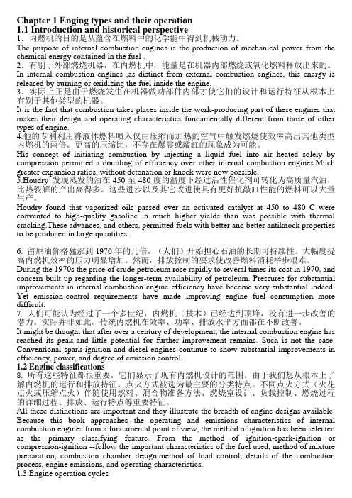
Internal Combustion Engine (PartⅠ) 1.2compression ring 气环 3.Oil ring 4.Piston pin 5.Piston 6connecting rod 油环 活塞销 活塞 连杆 连杆小头 连杆大头 连杆轴瓦 连杆盖
crank n.曲柄 曲柄 rod n.杆,棒 杆 rock n.岩石,摇动;v.摇动,摆动 岩石, 摇动, 岩石 摇动; 摇动
distribute v. cam n. valve n.阀 阀 filter n.;v.
交通运输专业英语
Lesson 2
Internal Combustion Engine (PartⅠ)
introduce:介绍,引荐;引进;输入,传入 :介绍,引荐;引进;输入,
由于燃料在发动机气缸内燃烧,因此发动机被称为内燃机。在内燃机中, 由于燃料在发动机气缸内燃烧,因此发动机被称为内燃机。在内燃机中, 空气燃油混合气被引入一个封闭的气缸,并在那里完成压缩点火。 空气燃油混合气被引入一个封闭的气缸,并在那里完成压缩点火。 The burning of the fuel (combustion) causes a rapid rise in cylinder pressure which is converted to useful mechanical energy by the piston and crank-shaft. 燃烧引起气缸内压力迅速上升, 燃烧引起气缸内压力迅速上升,这部分内能被活塞和曲轴转化成有用的 机械能。 机械能。 fuel 燃料 汽油 petrol(英)gasoline(美) 柴油 英 美 柴油diesel fuel oil 燃油 fuel pump 燃油泵 add fuel to the fire 火上加油 fuel up 加燃料 填肚子
燃油供给系统(英文版)

Supply Of Oil FuelsAccurate and complete analyses are difficult to obtain but specifications should confirm that certain parameters are not exceeded. Samples of the oil delivered should be kept for reference.Density of the oil must be given (usually measured at 15°C), since the consignment will be measured by weight. It will also be necessary to know this to adjust centrifuges to give purification.Viscosity is required, to calculate temperatures at which the fuel is treated and injected into the engine.Flash point for the fuel must not be below 60°C, although the actual value need not be stated. This minimum is for safety reasons.All residual fuels will contain contaminants, and to protect the engine some of these must be removed or reduced. Solid contaminants may consist of rust, sand, dust and refinery catalysts (catalytic fines), all of which are abrasives and will cause wear in fuel pumps, injectors, cylinder, liners, piston rings and exhaust valve seats. Liquid contaminants will be salt or fresh water, which may also contain other soluble substances; all of these are corrosive.Fuel to be used is first transferred from storage tanks to a settling tank in which it is heated to allow some water and sludge to settle out by gravity and be drained off. The fuel is then passed through the purification system and discharged to a daily tank.There are usually two daily tanks, used alternately, one in use while the other is being recharged. Settling and service tanks are lagged to conserve heat.A recommended standard of treatment for residual fuel to be used in a large engine requires two centrifuges of adequate capacity, operating in series. The first acts as a purifier to remove water, solubles, sludge etc while the second acts as a clarifier to remove solids. The purifier must be fitted with the correct disc or dam to match the oil density. The oil is heated before purification (max temp 98°C) and the rate of throughput is limited to assist efficientseparation. Both centrifuges must be cleaned frequently. Such systems can operate effectively on oils densities up to 0.99.From the service tank the treated oil is pumped through a pressurised fuel system to the engine. With the oil temperatures necessary for high viscosity fuel, and the possibility that a trace of water may still be present, it is necessary to maintain the engine pump suctions and circulating connections under pressure to inhibit boiling, gasification and cavitation.The oil first passes to the primary or supply pump which raises its pressure to about 4 bar; this pressure is maintained in the circulating returns. The circulating or booster pump draws oil from the primary discharge, raising its pressure to 10/12 bar and delivering it through the heater, viscosity regulator and fine filter to the main engine fuel pumps. The heater reduces the oil’s viscosity for efficient combustion. The temperature required will depend upon the oil quality, but to avoid fouling it should not exceed 150°C. The fine filter is of stainless steel mesh to filter out particles larger than 50 microns (0.05mm), or less for smaller engines. Filters must be changed over and cleaned regularly.In large two-stroke engines the fuel injectors will circulate fuel during the periods they are not actually injecting it to the cylinder. This ensures the system remains fully primed and at uniform temperature. The circulated oil is returned to a buffer or venting tank from which it passes either back to the low pressure part of the system before the circulating pump suction, or into the service tank. The fuel oil system is shown below.All pumps are in duplicate and have safe pressure relief valves fitted. All pipes carrying hot oil must be well lagged and fitted with trace heating if necessary. Fuel pipes must be clipped and supported to reduce stress from vibration.A tank containing diesel oil may be connected to the main heavy fuel system. This will allow flushing with light oil before stopping the engine for long periods of for maintenance.Various safety devices must be included in the system with alarms to detect loss in oil pressure, low tank level etc. Quick closing valves which can be operated from outside the machinery space must be fitted to all tanks and to the main engines. Fuel pumps must have remote switches by which they can be stopped in a emergency.There must be arrangements for venting and draining the system, cleaning strainers etc, but utmost care must be taken. Drain trays and save-alls, where fitted, must be kept clean; all joints must be kept tight with safeguards to prevent the possibility of hot oil spraying on to heated surfaces.Oil contained in tank with open drains should not normally exceed a temperature of 50°C or, if this is lower, may not exceed a temperature 20°C below the flash point of the oil.The ViscothermWhen burning heavy fuel oil in a diesel engine it is necessary to reduce the high viscosity of the fuel to a value at which correct atomisation can take place in the fuel injectors. This will allow intimate mixing of the fuel oil with heated air for ignition and efficient combustion. Viscosity of a fuel may be reduced by raising the temperature and it is passed through a heater to do this. Automatic control of the heater may be regulated either to maintain a constant temperature, or to measure and control the viscosity.It is possible that oils of varying properties are contained within a ship’s bunker tanks or even one tank, when its contents are from a number of different sources. Consequently, it is preferable that the actual viscosity of the fuel is controlled within those limits. In most casts this is regulated to have kinematic between 10 and 15 centistokes at 50°C (that is 50-70 seconds Redwood No. 1, at 100°F).The Viscotherm shown is an instrument which measures fuel oil viscosity at the heater discharge and regulates the heater temperature to control this. It consists of a small gear type pump rotated at a slow but constant speed (40 rpm) and is fitted within the fuel supply close to the heater discharge. The pump draws fuel from the system at a controlled rate and discharges it through a capillary tube. The form of flow within a capillary tube at corresponding speeds is such that the pressure difference between each end of the tube is directly proportional to the viscosity of the oil flowing through it.Pressures at the corresponding points are measured with Bourdon tubes and compared to read as viscosity. In addition these pressures are fed to a differential pressure transmitter which can automatically operate the heater control to maintain fuel viscosity within close limits.All parts of the instrument are of stainless steel. In the event of a failure of this control an oil bypass valve is included in the system and the temperature may then be controlled by hand or by a thermostat.Combustion of FuelThe general indications of good combustion are similar in any operating diesel engine; a clear exhaust, power produced and with balanced exhaust temperatures normal for the throttle setting. There should be no uneven running, knocking from cylinders or the fuel system.Viscosity, or resistance to flow, in a fuel oil is important when considering combustion. It must be low enough to ensure correct atomisation at the fuel injector. Since viscosity reduces as temperature is increased, it will be necessary to heat heavy fuel oil to reduce its viscosity to about 15 cSt at 50°C before atomisation for combustion.Atomisation is the splitting up of the fuel into very small droplets by the fuel injector forcing fuel at high pressure through small atomiser holes. The droplet size will depend upon the size of holes and the pressure difference between fuel pump discharge and that of the compressed air in the combustion chamber, and consequently the size of droplets may vary over the whole injection period. Atomised droplets have a high surface to mass ratio giving good heat transfer from the hot compressed air in the cylinder causing rapid evaporation andmixing.Penetration refers to the distance the oil droplets travel into the combustion space before mixing with the air and igniting. This will depend upon the droplet size (atomisation), velocity leaving the injector and the conditions within the combustion chamber. It is desirable that fuel should penetrate into the whole of the combustion space for good mixing, but droplets should not impinge on the internal surfaces before burning. The number of atomiser holes and their position will decide the spray pattern.Turbulence is the movement of compressed air and fuel within the combustion space before combustion occurs. This may have several causes. Swirl is imparted to the air during its entry at scavenge ports. It may be further agitated by the fuel spray pattern and the shape and movement of the piston crown. Turbulence will improve the mixing of fuel and air for effective and rapid combustion. It is particularly desirable for rapid combustion of heavy fuels in medium or higher speed engines.Compression Ignition is the term used to describe the combustion in diesel engines and they are often referred to as compression ignition engines. The combustion process may be considered as three consecutive phases. In phase one the atomised oil droplets emitted from the fuel valve nozzle into the combustion space at the start of injection will evaporate and mix with hot, compressed air and some chemical changes will also occur. The mixture will reach an ignitable condition and spontaneous combustion will commence. The time elapsed during this phase it termed the ignition delay or ignition lag.In phase two the ignition and start of combustion will set up a flame front which will accelerate through the chamber, enveloping and burning all the other droplets present, causing a very rapid generation of heat with a corresponding rise in pressure and temperature.During the ignition delay, the injector continued to inject fuel and, if this has built up a sufficient quantity, the rapid combustion and pressure rise will be quite violent, causing detonation, the shock loading creating a noise termed diesel knock.Following the rapid pressure rise in phase two, hot, turbulent conditions existing in the combustion chamber will ignite and burn the remainder of the measured fuel charge as it is injected. This is phase three; it is termed the controlled part of the combustion process as pressure is regulated by the rate at which fuel continues to be delivered. The cylinder pressure may start to reduce as the piston moves down after passing over top centre.Ignition quality of a fuel is the term used to denote the ignition delay, combustion characteristics and tendency to cause knock. It depends mainly upon the form of the hydrocarbon compounds in the fuel and no precise unit has been derived to measure this.The most usual measure of ignition quality of distillate fuels is the Cetane number. This is found by comparison of the ‘knock producing’ properties to those of mixtures containing an equivalent percentage of Cetane when burnt in a test engine. A high Centane number indicates a short ignition delay. Cetane numbers are not quoted in normal fuel specifications or analyses. Slow speed, two-stroke engines can operate efficiently of fuels down to Cetane number of about 24 but medium speed, four-stroke engines normally require a figure above 34; high speed engines need higher figures. Another measure which is similar to Cetane number but found from different parameters of the fuel, is termed its diesel index.For residual or blended fuels the ignition can be expressed as a CCAI value (calculated carbon aromacity index) or CII (calculated ignition index). The lower the CCAI value, the better the ignition quality. A limiting figure of 870 is suggested. These units take the viscosity into consideration.The ignition quality of a fuel is particularly important for each of starting an engine, or when operating at reduced power for long periods. It can be improved by increasing the compression ratio of the engine or by pre-heating the scavenge air. There will be design or operational limits to both of these.Variable Ignition Timing (VIT). If an engine operates for long periods at reduced power or speed, the residual heat in the main components of the combustion chamber will decrease, causing a lower air temperature after combustion. This will lead to an increase in the ignition delay of injected fuel, which will cause knocking or ‘rough running’ in the engine, with consequent damage from shock loads and poor combustion. This problem can be reduced by the use of variable ignition timing to advance the start of injection, allowing for the longer delay but maintaining ignition timing and the same peak pressure. In large, two-stroke engines, variable ignition timing is automatically superimposed on the normal fuel pump setting from the engine governor. Additional linkage from the governor will advance each pump setting over the range of lower speeds. Fuel pumps are designed to carry out necessary adjustment while the engine is running. This control can also be manually regulated to advance normal governor settings if it is known that fuel with low ignition quality is to be used.In medium speed engines, variable ignition timing is built in by shaping the profile of the pump plunger to give an earlier start of injection at lower fuel settings. Manual adjustment, advancing the timing for low ignition quality fuel, is fitted on some engines.Pilot Injection This is a system by which fuels with low ignition quality can be burnt smoothly and efficiently, even in medium or high speed engines. A small ‘pilot’ charge of finely atomised fuel is briefly injected very early during compression. This small charge is heated and vaporised, passing through its delay period and igniting just before the main charge of fuel is injected. Combustion of the pilot charge will cause high temperature and turbulence in the combustion space. This together with its flame front will cause the main charge of fuel to ignite and burn smoothly as it is injected. In this manner the violent pressure rise usual with these fuels is avoided. Combustion is efficient and the peak pressure is limited.Pilot injection can be implemented by two different methods. In the first case two separate injectors are fitted to each unit; both must be correctly timed. The pilot injector has fine nozzle holes to atomise the fuel at a moderate injection pressure and is timed to commence before the main valve. The main injector is situated in a position to give an effective fuel spray and it injects the main, measured charge at normal fuel injection pressure. This system with two valves is sometimes referred to as twin injection.The alternative method of pilot injection has one injector fitted to each unit. This injector is designed to inject the pilot charge with fine atomisation and must also inject the main fuel charge. To do this it requires variable nozzle holes and a two stage needle valve lift. Fuel pump drive for this system may require specially shaped cam profiles.Electronic Injection was a system introduced by MAN engines that electronically controlled fuel injection. The heart of the electronic injection system is a micro-processor to which the actual engine speed and crankshaft position are transmitted as output signals. When the desired speed is compared with the actual speed, the processor automatically retrieves the values of injection timing and pressure for any load under normal operating conditions. In the event of deviations from normal operating conditions additional signals are transmitted to the microprocessor either manually or by appropriate temperature and pressure sensors. The result is an engine operating at optimum injection pressure and timing at all times. Adjustments to the system during operation are possible.Corrections can be made for: adapting the injection system to varying conditions such as ballast voyages, bad weather; matching the engine to different fuels, ignition lag, cetane numbers, etc; readjusting for operation in the tropics or in winter; controlling the injection characteristics of individual cylinders, such as when running in; reducing the minimum slow running speed, such as when in canals.The most noticeable feature of a KEZ type engine with electronic injection, is the absence of a camshaft and individual fuel pumps. The fuel is delivered to high-pressure accumulator by normal fuel injection plunger pumps driven by gears and cams from the crankshaft. These pumps are located above the thrust bearing and, depending on the size and cylinder number of the engine, two or more of these pumps are used. To safeguard against failure of a pump or a pressure pipe, two independent fuel delivery pipes are placed between the high-pressure pumps and accumulator.The high-pressure accumulator generates a buffer volume to prevent the pressure in the injection valve from dropping below an acceptable limit when the fuel is withdrawn during injection into the cylinder. For the electronically controlled injections systems, metering of the fuel volume for one cylinder is not affected by limiting the delivery volume per stroke of the injection pump plunger as in conventional systems, but by limiting the duration of injection. This is initiated by an electronic controller, i.e. by a low voltage signal which controls the opening and closing action of an electro-hydraulic servo valve. The electrohydraulic valve is actuated by oil under pressure from two pumps and an air cushion-type accumulator.Sequential control ensures that according to the engine firing sequence, the correct engine cylinder is selected in the proper crank angel range and that the electronically controlled injection valve is actuated at the exact point of injection.For engine starting and reversing, the correct injection timing is linked with the electronically controlled starting air valve. Since electronically controlled starting valves have no time delay between the switching pulse and opening of the air valve, and since there are no flow losses, due to the elimination of the control air pipes, the starting air requirements are reduced in comparison with the former conventional air start system.The constant pressure maintained during fuel injection with the electronically controlled fuelinjection system, and the fact that the injection pressure can easily be matched to each load condition, lead to lower fuel consumption rates over the entire load range. It also means satisfactory operation at very slow speeds, which contributes favourably to the manoeuvrability of a vessel, a K3EZ 50/105C/CL engine on the test bed was operated at a dead slow speed of 30 rev/min, which had never been achieved before. The full load speed is 183 rev/min.Although this system never caught on in the early 1980’s with the advances in electronics it could easily returns in the near future.。
完整版内燃机专业英语翻译
Chapter 1 Enging types and their operation1.1 Introduction and historical perspective1.内燃机的目的是从蕴含在燃料中的化学能中得到机械动力。
The purpose of internal combustion engines is the production of mechanical power from the chemical energy contained in the fuel .2.有别于外部燃烧机器,在内燃机中,能量是在机器内部燃烧或氧化燃料释放出来的。
In internal combustion engines ,as distinct from external combustion engines, this energy is released by burning or oxidizing the fuel inside the engine.3.实际上正是由于燃烧发生在机器做功部件内部才使它们的设计和运行特征从根本上有别于其他类型的机器。
It is the fact that combustion takes places inside the work-producing part of these engines that makes their design and operating characteristics fundamentally different from those of other types of engine.4.他的专利利用将液体燃料喷入仅由压缩而加热的空气中触发燃烧使效率高出其他类型内燃机的两倍。
更高的压缩比,不存在爆震或敲缸的现象成为可能。
His concept of initiating combustion by injecting a liquid fuel into air heated solely by compression permitted a doubling of efficiency over other internal combustion engines.Much greater expansion ratios, without detonation or knock were now possible.5.Houdry 发现蒸发的油在450至480度的温度下经过活性催化剂可转化为高质量汽油,比热裂解的产出高得多。
发动机专业英语(柴油机和汽油机)
发动机专业英语(柴油机和汽油机)INTERNAL COMBUSTION ENGINE(内燃机)1 principle of operation (⼯作原理)1.1 Engine and power(发动机和功率)Engine is used to produce power. The chemical energy in fuel is converted to heat by the burning of the fuel at a controlled rate. This process is called combustion. If engine combustion occurs with the power chamber, the engine is called internal combustion engine. If combustion takes place outside the cylinder, the engine is called an external combustion engine. Engine used in automobiles are internal combustion heat engines. Heat energy released in the combustion chamber raises the temperature of the combustion gases with the chamber. The increase in gas temperature causes the pressure of the gases to increase. The pressure developed within the combustion chamber is applied to the head of a piston to produce a usable mechanical force, which is then converted into useful mechanical power.1.2 Engine Terms (发动机术语)Linking the piston by a connecting rod to a crankshaft causes the gas to rotate the shaft through half a turn. The power stroke “uses up”the gas, so means must be provided to expel the burnt gas and recharge the cylinder with a fresh petrol-air mixture:this control of gas movement is the duty of the valves; an inlet valve allows the new mixture to enter at the right time and an exhaust valve lets out the burnt gas after the gas has done its job.Engine terms are:TDC(Top Dead Center): the position of the crank and piston when the piston is farther away from the crankshaft.BDC(Bottom Dead Center): the position of the crank and piston when the piston is nearest to the crankshaft.Stroke: the distance between BDC and TDC; stroke is controlled by the crankshaft. Bore: the internal diameter of the cylinder. Swept volume: the volume between TDC and BDC.Engine capacity: this is the swept volume of all the cylinders, e.g. a four-stroke having a capacity of two liters(2000cm) has a cylinder swept volume of 50cm. Clearance volume: the volume of the space above the piston when it is at TDC. Compression ratio = (swept vol + clearance vol)/(clearance vol)Two-stroke: a power stroke every revolution of the crank.Four-stroke: a power stroke every other revolution of the crank..1.3 The Four-stroke Spark-ignition Engine Cycle(四冲程⽕花塞点⽕发动机循环)The spark-ignition engine is an internal-combustion engine with externally supplied in ignition, which converts the energy contained in the fuel to kineticenergy.(动能)The cycle of operations is spread over four piston strokes. To complete the full cycle it takes two revolutions of the crankshaft. The operating strokes are:Intake strokeThis stroke introduces a mixture of atomized gasoline and air into the cylinder. The stroke starts when the piston moves downward from a position near the top of the cylinder. As the piston moves downward, a vacuum, or low-pressure area, is created. During the intake stroke, one of the ports is opened by moving the inlet valve. The exhaust valve remains tightly closed.Compression strokeAs the piston moves upward to compress the fuel mixture trapped in the cylinder,the valves are closed tightly. This compression action heats the air/fuel mixture slightly and confines it within a small areacalled the combustion chamber.Power strokeJust before the piston reaches the top of its compression stroke, an electrical spark is introduced from a spark plug screwed into the cylinder head.The spark ignites the compressed, heated mixture of fuel and air in the combustion chamber to cause rapid burning. The burning fuel produces intense heat that causes rapid expansion of the gases compressed within the cylinder. This pressure forces the piston downward. The downward stroke turns the crankshaft with great force. Exhaust strokeJust before the bottom of the power stroke, the exhaust valve opens. This allows the piston, as it moves upward, to push the hot, burned gases out through the open exhaust valve.Then, just before the piston reaches its highest point, the exhaust valve closes and the inlet valve opens. As the piston reaches the highest point in the cylinder, known as TDC, it starts back down again. Thus, one cycle ends and another begins immediately.1.4 Engine Overall Mechanics(发动机总体机构)The engine has hundreds of other parts. The major parts of engine are engine block, engine heads, pistons, connecting rods, crankshaft and valves. The other parts are joined to make systems. These systems are the fuel system, intake system, ignition system, cooling system, lubrication system and exhaust system. Each of these systems has a definite function. These systems will discussed in detail later.New WordsPiston 活塞Connecting rod 连杆Crankshaft 曲轴Power stoke 活塞⾏程Expel 排出Valve ⽓阀inlet(intake) valve 进⽓阀exhaust valve 排⽓阀TDC 上⽌点BDC 下⽌点Bore 缸径swept volume 有效容积engine capacity 发动机排量clearance volume 余隙容积,燃烧室容积compression ratio 压缩⽐revolution 旋转,转数every other 每隔⼀个spread over 分布,遍及intake stroke 进⽓⾏程compression stroke 压缩⾏程knock 敲缸,敲打exhaust stroke 排⽓⾏程engine block 发动机缸体lubrication 润滑2 Engine Block and Cylinder Head(发动机机体和⽓缸盖)2.1 Engine Block(发动机机体)The engine block is the basic frame of the engine. All other engine parts either fit inside it or fasten to it. It holds the cylinders,water jackets, and oil galleries. The engine block also holds the crankshaft, which fastens to the bottom of the block. The camshaft also fits inside the block, except on overhead-cam engines (OHC). In most cars, this block is made of gray iron, or an alloy (mixture) of gray iron and other metals, such as nickel or chromium. Engine blocks are castings.Some engine blocks, especially those in smaller cars, are made of cast aluminum. This metal is much lighter than iron. However, iron wears better than aluminum. Therefore, the cylinders in most aluminum engines are lined with iron or steel sleeves. These sleeves are called cylinder sleeves. Some engine blocks are made entirely of aluminum.2.2 Cylinder Head(⽓缸盖)The cylinder head fastens to the top of the block, just as a roof fits over a house. The underside forms the combustion chamber with the top of the piston. The most common cylinder head types are the hemi, wedge, and semi-hemi. All three of these terms refer to the shape of the engine's combustion chamber. The cylinder head carries the valves, valve springs and the rockers on the rocker shaft, this part of the valve gear being worked by the push-rods. Sometimes the camshaft is fitted directly into the cylinder head and operates on the valves without rockers. This is called an overhead camshaft arrangement. Like the cylinder block, the head is made from either cast iron or aluminum alloy.2.3 Gasket(垫圈)The cylinder head is attached to the block with high-tensile steel studs. The joint between the block and the head must be gas-tight so that none of the burning mixture can escape. This is achieved by using cylinder head gasket. This is a sandwich gasket, i.e. a sheet of asbestos ([ ?s'best?s ]⽯棉)between two sheets of copper, both these materials being able to withstand the high temperature and pressures within the engine.2.4 Oil Pan or Sump(油底壳)The oil pan is usually formed of pressed steel. The oil pan and the lower part of the cylinder block together are called the crankcase; they enclose, or encase, the crankshaft. The oil pump in the lubricating system draws oil from the oil pan and sends it to all working parts in the engine. The oil drains off and runs down into the pan. Thus, there is constant circulation ofoil between the pan and the working parts of the engine.New Wordsengine block 缸体cylinder head ⽓缸盖fasten 使固定water jacket ⽔套oil gallery 油道camshaft 凸轮轴overhead-cam(OHC) 顶置凸轮gray iron 灰铸铁alloy 合⾦nickel 镍chromium 铬casting 铸件head cover 汽缸盖罩intake manifold 进⽓总管distributor 分电器oil pan 油底壳aluminum 铝be lined with 镶有cylinder sleeve ⽓缸套hemi 半球形wedge 楔型,楔⼊semi-hemi 准半球形rocker 摇臂push-rod 推杆gasket 衬垫high-tensile ⾼强度的stud 螺栓gas-tight 密封的asbestos ⽯棉crankcase 曲轴箱,曲柄箱encase 封闭,把…包起来drain off 排出,流出Review Question1.What do TDC, BDC, stroke, compression ratio and engine capacity stand for?2.How do you calculate swept volume and compression ratio?3.What controls the length of the stroke?4.List the main parts of the engine overall mechanics?5.What are the main function of the engine block?3 Piston Connecting Rod and Crankshaft(活塞连杆和曲轴)3.1 Piston Assembly (活塞总称)The piston is an important part of a four-stroke cycle engine. Most pistons are made from cast aluminum. The piston, through the connecting rod, transfers to the crankshaft the force create by the burning fuel mixture. This force turns the crankshaft.Thin, circular, steel bands fit into grooves around the piston to seal the bottom of the combustion chamber. These bands are called piston rings. The grooves into which they fit are called ring grooves. A piston pin fits into a round hole in the piston. The piston pin joins the piston to the connecting rod. The thick part of the piston that holds the piston is the pin boss. The piston itself, its rings and the piston pin are together called the piston assembly.3.2 Piston(活塞)To withstand the heat of the combustion chamber, the piston must be strong. It also must be light, since it travels at high speeds as it moves up and down inside the cylinder. The piston is hollow. It is thick at the top where it take the brunt of the heat and the expansion force. It is thin at the bottom, where there is less heat. The top part of the piston is the head, or crown. The thin part is the skirt The sections between the ring grooves are called ring lands.The piston crown may be flat, concave,dome or recessed. In diesel engine, the combustion chamber may be formed totally or in part in the piston crown, depending on the method of injection. So they use pistons with different shapes.3.3 Piston Rings(活塞环)As Fig.1-9 shows, piston rings fit into ring grooves near the of the piston. In simplest terms, piston rings are thin, circular pieces of metal that fit into grooves in the tops of the pistons.In modern engines, each piston has three rings. (Piston in older engines sometimes had four rings, or even five.) The ring’s outside surface presses against the cylinder walls. Rings provide the needed seal between the piston and the cylinder walls. That is, only the rings contact the cylinder walls. The top two rings are to keep the gases in the cylinder and are called compression rings. The lower one prevents the oil splashed onto the cylinder bore from entering the combustion chamber, and is called an oil ring.Chrome-face cast-iron compression rings are commonly used in automobile engines. The chrome face provide a very smooth, wear-resistant surface.During the power stoke, combustion pressure on the combustion rings is very high. It causes them to untwist. Some of the high-pressure gas gets in back of the rings. This force the ring face into full contact with the cylinder wall. The combustionpressure also holds the bottom of the ring tightly against the bottom of the ring groove. Therefore, high combustion pressure causes a tighter seal between the ring face and the cylinder wall.3.4 Piston Pin (活塞销)The piston pin holds together the piston and the connecting rod. This pin fits into the piston pin holes and into a hole in the top end of the connecting rod. The top end of is much smaller than the end that fits on the crankshaft. This small end fits inside the bottom of the piston. The piston pin fits through one side of the piston, through the small end of the rod, and then through the other side of the piston. It holds the rod firmly in place in the center of the piston. Pins are made of high-strengh steel and have a hollow center. Many pins are chrome-plated to help them wear better.3.5 Connecting rod (连杆)The connecting rod is made of forgedhigh-strength steel. It transmits and motion from the piston to the crankpin on the crankshaft. The connecting rod little end is connected to the piston pin. A bush madefrom a soft metal, such as bronze, is used for this joint. The lower end of the connecting rod fits the crankshaft journal. This is called the big end. For this big-end bearing, steel-backed lead or tin shell bearing are used. These are the same as those used for the main bearings. The split of the big end is sometimes at an angle, so that it is small enough to be withdrawn through the cylinder bore. The connecting rod is made from forged alloy steel.3.6 Crankshaft(曲轴)The crankshaft, in conjunction with the connecting rod, coverts the reciprocating motion of the piston to the rotary motion needed to drive the vehicle. It is usually made from carbon steel which is alloyed with a small proportion of nickel.The main bearing journals fit into the cylinder block and the big end journals align with the connecting rods. At the rear end of the crankshaft is attached the flywheel, and at the front end are the driving whells for the timing gears, fan, cooling water and alternator.The throw of the crankshaft, the distance between the main journal and the big end centers, controls the length of the stroke. The stroke is double the throw, and the stroke-length is the distance that the piston travels from TDC to BDC and vice versa.3.7 Flywheel (飞轮)The flywheel is the made from carbon steel. It fit s onto the rear of the crankshaft. As well as keeping the engine rotating between power strokes it also carries the clutch, which transmits the drive to the transmission, and has the starter ring gear around its circumference. There is only one working stroke in four so a flywheel is needed to drive the crankshaft during the time that the engine is performing the non-power strokes.New Words Comprise 由。
车辆工程专业英语

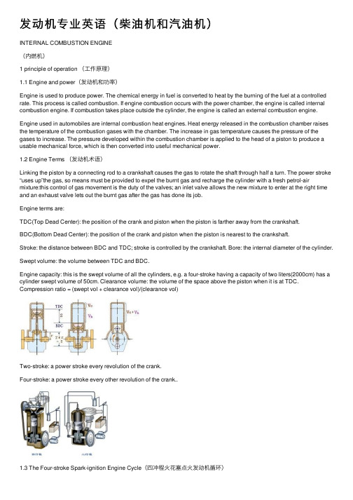
As their name implies, four-stroke internal combustion engines have four basic steps that repeat with every two revolutions of the crankshaft:① Intake stroke ② Compression stroke, ③ Power stroke, ④ Exhaust stroke. The four strokes will be illustrated in Fig.2.4. They draw in an air-fuel mixture to the cylinders, compress it, ignite and combust it, then discharge it. Repeating these four actions gives gasoline engines their power. The cycle begins at Top Dead Centre (TDC), when the piston is farthest away from the crankshaft. A cycle refers to the full travel of the piston from TDC to Bottom Dead Centre (BDC).
Cooling System
The cooling system regulates the engine temperature to an optimal level (80℃ to 90℃ at coolant temperature) by circulating the coolant throughout the engine under all operating conditions and during all seasons of the year. The cooling fan cools the coolant in the radiator and water pump circulates the coolant through the cylinder head and the cylinder block.
汽车专业英语课文翻译4

Fuel Supply System of Gasoline EngineAll the gasoline engines have substantially identical fuel systems and run on a mixture consisting of fuel vapor and air. The fuel system comprises the units designed to store, clear and deliver fuel, the units intended to clean air and a unit for preparing a mixture from fuel vapor and air.In a fuel system different components are used to supply fuel from the fuel tank into the engine cylinder. Some of the important components are fuel tank, fuel pump, fuel filter, carburetor, intake manifold and fuellines or tubes connecting the tank, pump and the carburetor.The fuel tank is a fuel container used for storing fuel. It is made of sheet metal. It is attached to the vehicle frame with metal traps and is located at the rear of the vehicle. They are mounted in a boot or boot-floor pan in case of front-engined cars and small commercial vehicles. In order to strengthen the tank as well as to prevent surging of fuel when the vehicle rounds a curve of suddenly stops, baffle plates are attached to the inside of the tank.A cap is used to close the filler opening of the tank. The fuel line is attached at or near the bottom of the tank with a filtering element placed at the connection. The other components of the fuel tank are the fuel gauge sending unit, a vent pipe, receiving unit. To prevent the dirt and water from entering the luggage compartment, a sealing strip is fitted between the fuel tank and boot floor pan. Moreover to limit the transmission of frame distortion to the tank giving rise to squeaking as the metal parts get rubbed together, rubber or felt pads are often fitted between the mountings and the tank. Provision is also made against drumming of the tank by these mountings. The tank may be placed at the side of the chassis frame for convenience in case of large commercial vehicles. The length of the connecting lines or tubes from the tank to the carburetor is also restricted by this at the same time.A porous filter is attached to the outlet lines. By drawing fuel from the tank through the filter, any water in the bottom of the tank as well as any dirt into the fuel gathers on the surface of the filter. To keep the fuel always under atmospheric pressure, the filter pipe or tank is vented.In order to prevent dirt in the fuel from entering the fuel pump or carburetor, fuel filters and screens are used in the fuel system. If the dirt is not removed from the fuel, the normal operation of these units will be prevented. The engine performance will also be reduced.The filter is either fitted inside the fuel tank and pump or operates as a separate unit connected between the fuel tank and pump or between pump and carburetor into the fuel lines. Carburetors are also provided filter screens while a filter element is provided in the fuel tank.The fuel filter used is generally a sediment bowl made of glass or metal and a strainer screen. When the fuel drawn from the tank passes through the filter (through the bowl and strainer screen), particles of dirt and water settle in the bottom of the bowl. In certain vehicles, a separate filter either of the disk or ceramic type is used. It is either located between the fuel pump and carburetor or in the fuel line.For connecting the fuel tank to the fuel pump, metallic tubes or synthetic rubber hose used are called fuel lines. They are usually positioned with metallic clips along the frame side members. The tubing or fuel lines are also used to connect fuel pump to the carburetor. In order to absorb vibration as well as prevent breakage of the fuel lines, a short flexible line is used between the fuel pump and the tank.In order to meter and caution the driver of the motor vehicle about the quantity of fuel consumed and left in the tank, a fuel gauge is used. It is generally fitted on dash board for easy reading of the fuel. It is usually a balancing coil type having construction similar to that of an oil gauge. It is generally electrically operated.It consists of a sending unit mounted on the fuel tank and a receiving unit having a caliberated gauge mounted on the instrument panel.A sending unit consists of a float controlled thermostat or variable resistor. With a float and the float arm extending into the fuel tank, the whole unit is mounted on it. The level of fuel in the tank varies the position of the float. The amount of electrical resistance within the variable resistor for controlling the amount of current sent to receiving unit on the instrument panel is determined by the float position.The receiving unit mounted on the dash board indicates the amount of fuel in the tank on a caliberated gauge by the amount of current received from the sending unit.On modern automobiles, two types of fuel gauges; thermostatic type and an electromagnetic type are used.In order to prevent the rapid wear and tear of engine operating components causing reduced performance air cleaner is fitted to the carburetor air intake, it is mounted on thecarburetor air-horn for trapping dirt. Before entering the carburetor, the air must pass through it.To reduce the noise produced by the air rushing into the carburetor, a silencing chamber is built into the air cleaner. In case the engine misfires back through the carburetor, it acts as the flame arrestor.There are in general three types of the air cleaners used in modern automobiles. They are (a) oil bath cleaner (b) oil-wetted mesh air cleaner (c) dry type air cleaner. The first two are also known as heavy duty air cleaner while the third is known as light duty air cleaner.Fuel pumps are the devices used to supply fuel from the fuel tank to the carburetor. There are in general two main types of fuel pumps used in automobiles. They are main types of fuel pumps used in automobiles. They are (a) mechanical fuel pump (b) electric fuel pump.汽油发动机的燃料供给系统所有的汽油发动机具有基本相同的燃料系统和运行的燃料蒸气和空气组成的混合物中。
内燃机燃料供给系统概述

控制信号
EDU ECU
油 箱
传感器信号
14
汽油机燃料供给系统概述 GASOLINE DELIVERY SYSTEM
一、化油器 Carburetor
15
二、电控汽油喷射系统 EFI System
空气流量的测量与空燃比的计算 燃油定量与点火正时 三效催化后处理与空燃比的反馈
16
三、汽油喷射方式 EFI Arrangement
• 电控汽油喷射系统 Electronic Fuel Injection System (EFI) SPI, PFI, MPI
4
二、柴油机的燃料供给系统 Diesel Injection System
• 泵管嘴喷射系统 Pump-line-nozzle system
• 泵喷嘴喷射系统 Unit Injector System
发动机的全面控制。
18
五、电控汽油喷射的优点
① 满足发动机各种工况对空燃比和点火提前角的不同要求; ② 燃油喷射系统可以使发动机的各个气缸获得均匀的混合气,以此提高 发动机的燃烧质量和稳定性,减少废气中的CO和HC的含量,有效提 高发动机排气净化程度; ③ 没有化油器中的狭窄喉管,减少了节流损失,不需要排气加热进气, 因而进气密度提高,充气效率改善; ④ 具有良好的瞬态响应特性,改善了汽车的加速性; ⑤ 采用闭环反馈控制方式,可满足三效催化剂对空燃比的严格要求; ⑥ 由于采用压力喷射,汽油雾化质量比化油器大为改善,有利于快速和 完全燃烧;
第一节 内燃机燃料供给系统
INTRODUCTION TO FUEL DEL IVERY SYSTEM
主要学习内容
内燃机燃料供给系统分类
柴油机燃料供给系统概述 汽油机燃料供给系统概述
- 1、下载文档前请自行甄别文档内容的完整性,平台不提供额外的编辑、内容补充、找答案等附加服务。
- 2、"仅部分预览"的文档,不可在线预览部分如存在完整性等问题,可反馈申请退款(可完整预览的文档不适用该条件!)。
- 3、如文档侵犯您的权益,请联系客服反馈,我们会尽快为您处理(人工客服工作时间:9:00-18:30)。
附录A 外文翻译—原文部分Fuel Supply System For An Internal Combustion EngineAbstractA pulsation damper is provided between and in series with a low pressure fuel system pipe and a high pressure pump of a fuel supply system. During startup of an engine,low pressure fuel supplied via the low pressure fuel system pipe is injected from an intake passage fuel injector. When the fuel pressure is equal to or less than a fuel pressure at which good startability can be maintained,the pulsation damper closes off communication between the high pressure fuel system pipe and the low pressure fuel system pipe using the spring force of a spring.Keywords: Fuel supply system; An internal combustion engine;A pulsation damper;A low pressure fuel system pipe and a high pressure pump;A fuel supply system for an internal combustion engine,comprising: a low pressure pump that is capable to pressurize fuel; a low pressure fuel supply passage that is capable to supply fuel that was pressurized by the low pressure pump to a low pressure fuel injection mechanism which injects fuel into an intake passage; a branch passage that branches off from the low pressure fuel supply passage and through which the fuel that was pressurized by the low pressure pump flows; a high pressure pump which is capable to pressurize the fuel supplied via the branch passage,the high pressure pump being driven by the internal combustion engine; a high pressure fuel supply passage that is capable to supply fuel that was pressurized by the high pressure to a high pressure fuel injection mechanism which injects fuel into a cylinder; and a pulsation reducing mechanism provided on an intake side of the high pressure pump,wherein,when the internal combustion engine is started by only injecting fuel from the low pressure supply passage into the intake passage,the pulsation reducing mechanism closes off communication between the low pressure fuel supply passage and the high pressure fuel supply passage until a pressure of fuel in the low pressure fuel supply passage reaches a predetermined pressure value required for starting the internal combustion engine.Background of the invention :1. Field of the InventionThe invention relates to a fuel supply system for an internal combustion engine provided with a fuel injection mechanism that injects fuel at high pressure into a cylinder (i.e.; a fuel injector for in-cylinder injection,hereinafter referred to as “in-cylinder fuel injector”) and a fuel injection mechanism that injects fuel into an intake passage or an intake port (i.e.,a fuel injector for intake passageinjection,hereinafter referred to as “intake passage fuel injector”). More particularly,the invention relates to a fuel supply system that can improve startability of an internal combustion engine.2. Description of the Related ArtA gasoline engine is known which is provided with a fast fuel injection valve for injecting fuel into a combustion chamber of the engine (i.e.,an in-cylinder fuel injector) and a second fuel injection valve for injecting fuel into an intake passage (i.e.,an intake passage fuel injector),and divides the injected fuel between the in-cylinder fuel injector and the intake passage fuel injector according to the engine speed and engine load. Also,a direct injection gasoline engine is also known which is provided with only a fuel injection valve for injecting fuel into the combustion chamber of the engine (i.e.,an in-cylinder fuel injector). In a high pressure fuel system that includes an in-cylinder fuel injector,fuel of which the pressure has been increased by a high pressure fuel pump is supplied to the in-cylinder fuel injector via a delivery pipe. The in-cylinder fuel injector then injects the high pressure fuel into the combustion chamber of each cylinder of the internal combustion engine.In addition,a diesel engine is also known which has a common rail type fuel injection system. In this common rail type fuel injection system,fuel which has been increased in pressure by a high pressure fuel pump is stored in a common rail. The high pressure fuel is then injected into the combustion chamber of each cylinder of the diesel engine from the common rail by opening and closing an electromagnetic valve.In order to increase the pressure of (i.e.,pressurize) the fuel in this kind of internal combustion engine,a high pressure fuel pump is provided which is driven by a cam provided on a driveshaft that is connected to a crankshaft of the internal combustion engine.Japanese Patent Application Publication No. JP-A-2005-139923 describes a high pressure fuel supply system for an internal combustion engine that can reduce vibrational noise when only a small amount of fuel is required by the internal combustion engine,such as during idling,while being able to deliver the necessary amount of fuel over the entire operating range of the internal combustion engine. This high pressure fuel supply system for an internal combustion engine has a two single plunger type high pressure fuel pumps each of which have a spill valve that spills fuel drawn into a pressurizing chamber that is divided by a cylinder and a plunger that moves back and forth in the cylinder,from that pressurizing chamber. When fuel is pressurized and delivered from the pressurizing chamber to the high pressure fuel system,the amount of fuel delivered is adjusted by controlling the spill valve open andclosed. One of these high pressure fuel pumps is a first high pressure fuel pump in which the lift amount of the plunger is small and the other high pressure fuel pump is a second high pressure fuel pump in which the lift amount of the plunger is large. In addition to these two high pressure fuel pumps,the high pressure fuel supply system for an internal combustion engine also includes control means. The control means controls the spill valve of each high pressure fuel pump according to the amount of fuel required by the internal combustion engine,such that fuel is pressurized and delivered using only the first high pressure fuel pump when the amount of required fuel is small,and fuel is pressurized and delivered using at least the second high pressure fuel pump when the amount of required fuel is large.According to this high pressure fuel supply system for an internal combustion engine,of the two high pressure fuel pumps,the first high pressure fuel pump has a plunger with a small lift amount so the rate of pressure increase is small and a large amount of water hammer is also self-suppressed. That is,with the high pressure fuel supply system,the vibrational noise produced when the required fuel quantity is small can be preferably reduced by controlling the spill valve of each of the high pressure fuel pumps so that only the first high pressure fuel pump is used when the amount of fuel required for the internal combustion engine is small such as during idling. On the other hand,the second high pressure fuel pump has a plunger with a large lift amount so pressurizing and delivering fuel using at least this second high pressure fuel pump also makes it possible to deliver the required fuel quantity when the amount of fuel required by the internal combustion engine increases to the point where it can no longer be delivered by the first high pressure fuel pump alone. That is,providing two high pressure fuel pumps having plungers with different lift amounts in this way enables the required amount of fuel to be delivered throughout the entire operating range of the internal combustion engine,while reducing vibrational noise when the amount of required fuel is small.In Japanese Patent Application Publication No. JP-A-2005-139923,the high pressure fuel supply system for a V-type 8 cylinder internal combustion engine having an in-cylinder fuel injector in each cylinder is provided with a high pressure fuel pump for each bank. Tip ends that branch off from a low pressure fuel passage which is connected to the fuel tank are connected to galleries of these high pressure fuel pumps. For each bank,a pulsation damper is provided midway between the branch portion of the low pressure fuel passage and the portion that connects with the gallery. This pulsation damper suppresses the pulsation in the fuel pressure in the low pressurefuel passage when the high pressure fuel pump is operating. At engine startup in this kind of a direct injection engine having only an in-cylinder fuel injector,fuel is unable to be delivered by the high pressure fuel pump until the engine turns over. Therefore,low pressure fuel is delivered by a feed pump to the fuel injection for in-cylinder injection. Therefore,the pulsation damper is designed to provide communication between the high pressure pipe system and the low pressure pipe system. For example,FIG. 6 is a sectional view of such a pulsation damper 215 ,FIG.7 is a sectional view taken along line VII-VII of FIG. 6 ,and FIG. 8 is a sectional view taken along line VIII-VIII of FIG. 7. As shown in FIGS. 6 to 8,grooves 223 A,223 B,223 C,and223 D are provided in an end face (i.e.,the upper surface in FIG. 8) that abuts against a contacting member 226 A of the pulsation damper 215 . Therefore,when the feed pressure is low,the spring 226 D presses the contacting member 226 A against the upper surface of the member that forms the inlet 222 and the outlet 224 . In this way,the structure is such that even if pressure is applied by the spring 226 D,the grooves 223 A,223 B,223 C,and223 D enable fuel delivered from the inlet 222 (i.e.,the feed pump side) to flow into the outlet 224 (i.e.,the high pressure fuel pump side) as shown by the dotted line in FIG. 8. On the other hand,as described above,an engine is known which includes,for each cylinder,an in-cylinder fuel injector that injects fuel into a combustion chamber of the engine and an intake passage fuel injector that injects fuel into an intake passage. In this engine,fuel is injected divided between the in-cylinder fuel injector and the intake passage fuel injector according to the engine speed and the load on the internal combustion engine. This engine is also providedwith the pulsation damper shown in FIGS. 6 to 8.However,in this kind of engine,the following problems occur when starting the engine by injecting fuel with an intake passage fuel injector. When fuel is delivered by a feed pump at engine startup,the volume of pipe that needs to be charged with fuel becomes significantly larger. That is,when the engine is started with fuel injected from the intake passage fuel injector,despite the fact that fuel can be delivered to the intake passage fuel injector with the feed pump by simply charging only the low pressure pipe with fuel,the pulsation damper is structured such that the high pressure pipe system and the low pressure pipe system are communicated or open to one another. Therefore,fuel is unable to be delivered to the intake passage fuel injector bythe feed pump unless both the low pressure pipe and the high pressure pipe are charged with fuel. As a result,it takes time for the feed pressure to rise,thereby adversely affecting startability (i.e.,increasing the start time).Summary of the inventionThis invention thus provides a fuel supply system for an internal combustion engine,which is capable of improving startability of an internal combustion engine that includes a fuel injection mechanism for injecting fuel at high pressure into a cylinder (i.e.,in-cylinder fuel injector) and a fuel injecting mechanism for injecting fuel into an intake passage or an intake port (i.e.,an intake passage fuel injector).A first aspect of the invention relates to a fuel supply system for an internal combustion engine which includes a low pressure fuel supply passage that supplies fuel that was pressurized by a low pressure pump to a low pressure fuel injection mechanism which injects fuel into an intake passage; a branch passage that branches off from the low pressure fuel supply passage and supplies fuel to a high pressure pump that is driven by the internal combustion engine; a high pressure fuel supply passage that supplies fuel that was pressurized by the high pressure pump to a high pressure fuel injection mechanism which injects fuel into a cylinder; and a pulsation reducing mechanism provided on the intake side of the high pressure pump. The pulsation reducing mechanism closes off communication between the low pressure fuel supply passage and the high pressure fuel supply passage when a pressure of fuel in the low pressure fuel supply passage is lower than a predetermined value.According to this first aspect,the high pressure pump which is driven by the internal combustion engine does not operate during startup of the internal combustion engine. In this case,the internal combustion engine is started by injecting fuel that has been pressurized by the low pressure pump from the low pressure fuel injection mechanism via the low pressure fuel supply passage. In this case,during startup of the internal combustion engine when the pressure of fuel in the low pressure fuel supply passage is low,the pulsation reducing mechanism closes off communication between the low pressure fuel supply passage and the high pressure fuel supply passage. Therefore,fuel can be delivered to the low pressure fuel injection mechanism simply by charging the low pressure fuel supply passage with fuel using the low pressure pump. Accordingly,there is no need to charge the high pressure fuel supply passage with fuel using the low pressure pump so the low pressure fuel supply passage and the branch passage that provides communication between the low pressure fuel supply passage and the high pressure pump can be charged with fuel quickly,and fuel can be quickly injected from the low pressure fuel injection mechanism. As a result,startability of an internal combustion engine provided with a fuel injectionmechanism that injects fuel at high pressure into the cylinder and a fuel injection mechanism that injects fuel into the intake passage or intake port can be improved.附录B 外文翻译—译文部分内燃机的燃油供应系统摘要在低压燃油供应系统管道和燃油供应系统的高压泵之间有一系列的有节奏的脉动衰减节气阀。