2019年车辆工程专业毕业论文_外文翻译1.doc
车辆工程毕业设计---英文翻译

车辆工程专业英文翻译原文:The controllable suspension system can improve both ride comfort and handling safety, which has become one research focus in the field of vehicle engineering since1950s.The full-car generally consists of four quarter-car suspension systems(QC)withstrong coupling characteristics,which yield strong coupling effects on vertical,pitch androll movement suspension performances.So far,an effective coordinated control methodfor the full-car with multiple sub-suspension systems has not been proposed.The best ideais to decouple the full-car into four independent QCs1,such that the sophisticated active orsemi-active control scheme for QC suspension can be directly employed,and thus simplifythe complicated controller synthesis for the full-car suspension and improve the real-timeproperty of control system,which has important theoretical and engineering values forrealizing the practical application of controllable suspension.This thesis focuses on the structural decoupling control study of half-car suspension,which has vertical and pitch movements.Firstly,the passive half-car dynamic model isestablished and transferred into the model involving two similar standard QC dynamicmodels.It is found that a coupling damping force exists in the sprung mass,and it can becompensated through adding a damping force in the unsprung mass, in which the half-carsuspension could be decoupled into two independent QCs.Furthermore,a new QCsuspension design with double controllable dampers is proposed on basis of the definedcoupling damping force,in which the traditional passive damper is normally replaced bythe sprung controllable dampe.Another damper named the unsprung controllable damperis installed between the lower control arm and linkage of vehicle controlled by the pitchangular acceleration,which plays role in compensating the yielded coupling damping force.Thus the suspension structural decoupling of half-car can be conveniently achieved and effectiveness of the proposed structural decoupling method of half-car suspension is verified.Finally,three kinds of control manners i.e.,active versus active,semi-activeversus active and semi-active versus semi-active,are fully discussed for the sprung and unsprung controllable dampers,respectively.The proposed active and semi-active slidingmode control schemes for the sprung controllable damper in QC are applied for thedecouplinghalf-car suspension robust control due to the uncertainty of vehicle load,andhe semi-active control manner chooses the semi-active controllable magneto-rheologicaldamper.As a result, the proposed both active versus active and semi-active versus active control manners could achieve the ideal multi-objective suspension performances for thehalf-car,and the proposed structural decoupling control method can be further extended to realize coordinated control of full-vehicle suspension system with multiple sub-suspension.Engineering vehicles working condition is usually relatively poor,coupled with thelimitations of the performance of the vehicle suspension system.It makes these vehicles' driveralways in the vibration of the high strength,and influences the driver's work efficiency,seriously hurts to the driver's spine,and directly leads to the disease.In order to reducevibration to the driver,this thesis usually takes the seat suspension system to isolate vibration,and uses the appropriate control strategies for seat suspension.It can effectively attenuate thevibration caused by uneven ground,reduce the vibration energy passed on to the driver's body,and improve the drivers'ride comfort.Magneto-rheological fluid is a kind of intelligent material,which has good rheologicalproperties.It can be the first choice of the semi-active suspension shock absorber material.According to the characteristics of magneto-rheological fluid,it can be made a lot of productswhich are used in mechanical engineering,civil engineering,etc.The most prominent exampleis magneto-rheological damper for vibration control in cable suspension bridge vibration,high-rise isolation,etc.In addition,the magnetic fluid rheostat vibration application of suspensionsystem is an important domain,including vehicle suspension system and vehicle seatsuspension system.In the suspension of the magneto-rheological damper applications,it ismainly for dissipation produced by the road excitation of vehicle and driver's vibration energy,to improve the ride comfort.Due to its good controllability,wide dynamic range,fast response,low power requirement and comparatively simple structure,magnetorheological(MR)dampers has become one of the focus research projects in automotive semi-active suspension.Besides damping force and dynamic range,the dynamic response is another important parameter of MR dampers,which isa key part of automotive MR semi-active suspension system.The dynamic response is valuable because it is one of the critical factors that determine the practical effectiveness of automotive MR dampers,the applications range of MR dampers and the controlling period directly.In this thesis,the dynamic response of automotive MR dampers is investigated and the effects of various conditions are considered.The main contributions include the following:(1)The properties and applications of MR fluid is reviewed firstly,the importance of the study on MR dampers dynamic response is discussed,and the present situation and existing problems of the study are summarized.Based on the present problems of the study,the main work is put forward.(2)Based on the hydrodynamics theory and working modes of MR dampers,applying the constitutive equations of Newton and Bingham fluid respectively,the parallel plates and annular duct based rheological equations are derived,the calculation approach of damping force is gained,and the theoretical relation between applied current,piston velocity and damping force is determined,which establishes he theoretical basis for the research of MR dampers dynamic response,propose of test approach and design of test system.Based on theoretical analysis of damping force,the calculation model of MR dampers dynamic response is built by analyzing the unstable state of MR fluid between parallel plates.Furthermore, driving by current source,the effect of the connecting way(parallel or serial)of electromagnetic coils is analyzed theoretically.(3)According to the damping force function and practical condition of dampers,an experimental approach for finding the dynamic response of automotive MR dampers and corresponding data processing are offered,the corresponding test system is developed, including some important parts of the test system,such as current driver based on PWM method,and its output characteristic and dynamic response are investigated theoretically and experimentally.译文:可控悬架系统能够同时提高车辆驾乘舒适度与操控安全性,因而具有出色的综合悬架性能,从上世纪五十年代起,就是国际车辆工程领域的研究热点课题之一。
车辆工程专业毕业论文_外文翻译
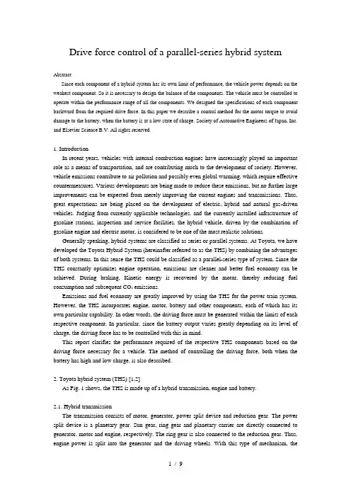
Drive force control of a parallel-series hybrid systemAbstractSince each component of a hybrid system has its own limit of performance, the vehicle power depends on the weakest component. So it is necessary to design the balance of the components. The vehicle must be controlled to operate within the performance range of all the components. We designed the specifications of each component backward from the required drive force. In this paper we describe a control method for the motor torque to avoid damage to the battery, when the battery is at a low state of charge. Society of Automotive Engineers of Japan, Inc. and Elsevier Science B.V. All rights reserved.1. IntroductionIn recent years, vehicles with internal combustion engines have increasingly played an important role as a means of transportation, and are contributing much to the development of society. However, vehicle emissions contribute to air pollution and possibly even global warming, which require effective countermeasures. Various developments are being made to reduce these emissions, but no further large improvements can be expected from merely improving the current engines and transmissions. Thus, great expectations are being placed on the development of electric, hybrid and natural gas-driven vehicles. Judging from currently applicable technologies, and the currently installed infrastructure of gasoline stations, inspection and service facilities, the hybrid vehicle, driven by the combination of gasoline engine and electric motor, is considered to be one of the most realistic solutions.Generally speaking, hybrid systems are classified as series or parallel systems. At Toyota, we have developed the Toyota Hybrid System (hereinafter referred to as the THS) by combining the advantages of both systems. In this sense the THS could be classified as a parallel-series type of system. Since the THS constantly optimizes engine operation, emissions are cleaner and better fuel economy can be achieved. During braking, Kinetic energy is recovered by the motor, thereby reducing fuel consumption and subsequent CO2 emissions.Emissions and fuel economy are greatly improved by using the THS for the power train system. However, the THS incorporates engine, motor, battery and other components, each of which has its own particular capability. In other words, the driving force must be generated within the limits of each respective component. In particular, since the battery output varies greatly depending on its level of charge, the driving force has to be controlled with this in mind.This report clarifies the performance required of the respective THS components based on the driving force necessary for a vehicle. The method of controlling the driving force, both when the battery has high and low charge, is also described.2. Toyota hybrid system (THS) [1,2]As Fig. 1 shows, the THS is made up of a hybrid transmission, engine and battery.2.1.Hybrid transmissionThe transmission consists of motor, generator, power split device and reduction gear. The power split device is a planetary gear. Sun gear, ring gear and planetary carrier are directly connected to generator, motor and engine, respectively. The ring gear is also connected to the reduction gear. Thus, engine power is split into the generator and the driving wheels. With this type of mechanism, therevolutions of each of the respective axes are related as follows. Here, the gear ratio between the sun gear and theFig. 1. Schematic of Toyota hybrid system (THS).ring gear is ρ:where Ne is the engine speed, Ng the generator speed and Nm the motor speed.Torque transferred to the motor and the generator axes from the engine is obtained as follows:where Te is the engine torque.The drive shaft is connected to the ring gear via a reduction gear. Consequently, motor speed and vehicle speed are proportional. If the reduction gear ratio isη, the axle torque is obtained as follows:where Tm is the motor torque.As shown above, the axle torque is proportional to the total torque of the engine and the motor on the motor axis. Accordingly, we will refer to motor axis torque instead of axle torque.2.2. EngineA gasoline engine having a displacement of 1.5 l specially designed for the THS is adopted [3]. This engine has high expansion ratio cycle, variable valve timing system and other mechanisms in order to improve engine efficiency and realize cleaner emissions. In particular, a large reduction in friction is achieved by setting the maximum speed at 4000 rpm (=Ne max).2.3. BatteryAs sealed nickel metal hydride battery is adopted. The advantages of this type of battery are high power density and long life. this battery achieves more than three times the power density of those developed for conventional electric vehicles [4].3. Required driving force and performanceThe THS offers excellent fuel economy and emissions reduction. But it must have the ability to output enough driving force for a vehicle. This section discusses the running performance required of the vehicle and the essential items required of the respective components.Road conditions such as slopes, speed limits and the required speed to pass other vehicles determine the power performance required by the vehicle. Table 1 indicates the power performance needed in Japan.3.1. Planetary gear ratioρThe planetary gear ratio (ρ) has almost no effect on fuel economy and/or emissions. This is because the required engine power (i.e. engine condition) depends on vehicle speed, driving force and battery condition, and not on the planetary gear ratio. Conversely, it is largely limited by the degree of installability in the vehicle and manufacturing aspects, leaving little room for design. In the currently developed THS, ρ=0.385.3.2. Maximum engine powerSince the battery cannot be used for cruising due to its limited power storage capacity, most driving is reliant on engine power only. Fig. 2 shows the power required by a vehicle equipped with the THS, based on its driving resistance. Accordingly, the power that is required for cruising on a level road at 140 km/h or climbing a 5% slope at 105 km/h will be 32 kW. If the transmission loss is taken into account, the engine requires 40 kW (=Pe max) of power. The THS uses an engine with maximum power of 43 kW in order to get good vehicle performance while maintaining good fuel economy.3.3. Maximum generator torqueAs described in Section 2, the maximum engine speed is 4000 rpm (=Ne max). To attain maximum torque at this speed, maximum engine torque is obtained as follows:From Eq. (3), the maximum torque on the generator axis will be as follows:This is the torque at which the generator can operate without being driven to over speed. Actually, higher torque is required because of acceleration/deceleration of generator speed and dispersion of engine and/or generator torque. By adding 40% torque margin to the generator, the necessary torque is calculated as follows:3.4. Maximum motor torqueFrom Fig. 3, it can be seen that the motor axis needs to have a torque of 304 Nm to acquire the 30% slope climbing performance. This torque merely balances the vehicle on the slope. To obtain enough starting and accelerating performance, it is necessary to have additional torque of about 70 Nm, or about 370 Nm in total.From Eq. (2), the transmitted torque from the engine is obtained as follows:Consequently, a motor torque of 300 Nm (=T m max) is necessary.3.5. Maximum battery powerAs Fig. 2 shows, driving power of 49 kW is needed for climbing on a 5%slope at 130 km/h. Thus, the necessary battery power is obtained by subtracting the engine-generated power from this. As already discussed, if an engine having the minimum required power is installed, it can only provide 32 kW of power, so the required battery power will be 17 kW. If the possible loss that occurs when the battery supplies power to the motor is taken into account, battery power of 20 kW will be needed. Thus, it is necessary to determine the battery capacity by targeting this output on an actual slope. Table 2 lists the required battery specifications.Table 3 summarizes the specifications actually adopted by the THS and the requirements determined by the above discussion. The required items represent an example when minimum engine power is selected. In other words, if the engine is changed, each of the items have to be changed accordingly.4. Driving force controlThe THS requires controls not necessary for conventional or electric vehicles in order to controlthe engine, motor and generator cooperatively. Fig. 4 outlines the control system.Fig. 4. Control diagram of the THS.Inputs of control system are accelerator position, vehicle speed (motor speed), generator speed and available battery power. Outputs are the engine-required power, generator torque and motor torque.First, drive torque demanded by the driver (converted to the motor axis) is calculated from the accelerator position and the vehicle speed. The necessary drive power is calculated from this torque and the motor speed. Required power for the system is the total of the required drive power, the required power to charge the battery and the power loss in the system. If this total required power exceeds the prescribed value, it becomes required engine power. If it is below the prescribed value, the vehicle runs on the battery without using the engine power. Next, the most efficient engine speed for generating engine power is calculated; this is the engine target speed. The target speed for the generator is calculated using Eq. (1) with engine target speed and motor speed. The generator torque is determined by PID control. Engine torque can be calculated in reverse by using Eq. (3) and the torque transferred from the engine to the motor axis can be calculated from (2). The motor torque is obtained by subtracting this torque from the initially calculated drive torque. Since it is not possible to produce a torque whereby the motor consumption power exceeds the total of the generator-generated power and the power supplied by the battery, it is necessary to control the motor power (torque) within this total power. Fig. 5 shows the control method. The sum of the power form the generator and the available battery power become the power that can be used by the motor. The available motor torque can be obtained by dividing this combined power by the motor speed. When the motor speed is low, if the calculated motor torque exceeds the motor specification of torque the motor torque is determined by the specification. By controlling the motor torque requirement with this limited torque, the motor consumption power can be controlled to within the available power. If the available battery power is large enough, the available motor torque hardly limits the motor torque. Conversely, when the charge is low, the motor torque is frequently limited.Fig. 6 shows the respective maximum drive torque of the battery, the engine, and the engine plus the battery while running based on the controls above, when the THS has the components as specified in Section 3.5. ConclusionsThis paper discussed the control of drive power in the Toyota Hybrid System. The following conclusions were obtained:●The performance required for each component can be determined by reversely calculating powerperformance required for a vehicle.●The available battery power varies according to its state of charge. However, by limiting themotor torque, the battery power can be controlled to within the battery's available power.混合动力系统驱动力的串并联控制摘要由于混合动力系统的每个部分都有自己的极限性能,所以汽车动力取决于最脆弱的哪一个组成部分。
车辆工程专业外文翻译
南京理工大学紫金学院毕业设计(论文)外文资料翻译系:机械工程系专业:车辆工程姓名:学号:外文出处:IEEE Transactions on Energy Conversion 附件: 1.外文资料翻译译文;2.外文原文注:请将该封面与附件装订成册。
附件1:外文资料翻译译文内燃-线性发电集成动力系统的动圈式电机的改进摘要——本文探讨了动圈式线性电机(MCLM)在内燃-线性发电集成动力系统(ICLG) 的使用,这是一个混合动力电动汽车关于分布式发电和应急电源的新颖的解决方案。
根据分析MCLM的基本结构,提出一种改进的管状MCLM配备:准·哈尔巴赫磁化磁铁,这是一个分析等效磁路(EMC)模型。
在EMC模型中测量一个4 kn原型,结果显示良好。
而对比动磁式线性电机(MMLM),该机器的优点是动质量少,响应更快和更好的可控性。
关键词——自由活塞发动机、线性发电机,线性电机,发电机。
I 介绍一个内燃-线性发电集成动力系统(ICLG),也被称为自由活塞能源转换器,是一个集成一个自由活塞发动机和一个线性电机的机器。
这个概念提供了一个解决混合电动汽车、分布式发电、和应急电源供应等问题的新颖的方案。
作为一个单缸ICLG图1所示,无曲轴在可靠性、效率、燃料消费,和排放等方面有好处。
额外的操作能力的具有可变压缩比,允许使用更有前途的、相同质量而费用较低的点火燃烧,更容易过渡到未来燃料。
然而,这要求有严格的控制系统和电气机器,这个概念的主要缺点在电力系统。
图1 ICLG综合电力系统为实现ICLG概念,电机必须有高推力、低移动的大规模、高发电效率、快速响应和高可控性这些特定的苛刻的要求。
这是因为增加的移动质量负面影响了最大频率和转换系统的功率密度。
高效率是这一能量变换器竞争力的重要方面。
快速响应和高可控性是正确计时每个冲程的活塞的往复运动的两个先决条件,避免活塞和腔室头之间的碰撞。
此外,双向可逆控制对达到目的和克服失火也是必须的。
毕业设计论文外文文献翻译汽车专业汽修点火系统中英文对照
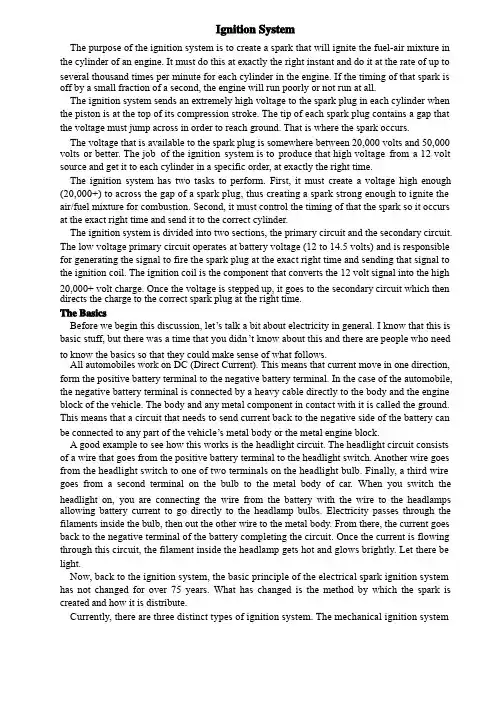
Ignition SystemThe purpose of the ignition system is to create a spark that will ignite the fuel-air mixture in the cylinder of an engine. It must do this at exactly the right instant and do it at the rate of up to several thousand times per minute for each cylinder in the engine. If the timing of that spark is off by a small fraction of a second, the engine will run poorly or not run at all.The ignition system sends an extremely high voltage to the spark plug in each cylinder when the piston is at the top of its compression stroke. The tip of each spark plug contains a gap that the voltage must jump across in order to reach ground. That is where the spark occurs.The voltage that is available to the spark plug is somewhere between 20,000 volts and 50,000 volts or better. The job of the ignition system is to produce that high voltage from a 12 volt source and get it to each cylinder in a specific order, at exactly the right time.The ignition system has two tasks to perform. First, it must create a voltage high enough (20,000+) to across the gap of a spark plug, thus creating a spark strong enough to ignite the air/fuel mixture for combustion. Second, it must control the timing of that the spark so it occurs at the exact right time and send it to the correct cylinder.The ignition system is divided into two sections, the primary circuit and the secondary circuit. The low voltage primary circuit operates at battery voltage (12 to 14.5 volts) and is responsible for generating the signal to fire the spark plug at the exact right time and sending that signal to the ignition coil. The ignition coil is the component that converts the 12 volt signal into the high 20,000+ volt charge. Once the voltage is stepped up, it goes to the secondary circuit which then directs the charge to the correct spark plug at the right time.The BasicsBefore we begin this discussion, let’’s talk a bit about electricity in general. I know that this is Before we begin this discussion, letbasic stuff, but there was a time that you didn’’t know about this and there are people who need basic stuff, but there was a time that you didnto know the basics so that they could make sense of what follows.All automobiles work on DC (Direct Current). This means that current move in one direction, form the positive battery terminal to the negative battery terminal. In the case of the automobile, the negative battery terminal is connected by a heavy cable directly to the body and the engine block of the vehicle. The body and any metal component in contact with it is called the ground. This means that a circuit that needs to send current back to the negative side of the battery can be connected to any part of the vehicle’’s metal body or the metal engine block.be connected to any part of the vehicleA good example to see how this works is the headlight circuit. The headlight circuit consists of a wire that goes from the positive battery terminal to the headlight switch. Another wire goes from the headlight switch to one of two terminals on the headlight bulb. Finally, a third wire goes from a second terminal on the bulb to the metal body of car. When you switch the headlight on, you are connecting the wire from the battery with the wire to the headlamps allowing battery current to go directly to the headlamp bulbs. Electricity passes through the filaments inside the bulb, then out the other wire to the metal body. From there, the current goes back to the negative terminal of the battery completing the circuit. Once the current is flowing through this circuit, the filament inside the headlamp gets hot and glows brightly. Let there be light.Now, back to the ignition system, the basic principle of the electrical spark ignition system has not changed for over 75 years. What has changed is the method by which the spark is created and how it is distribute.Currently, there are three distinct types of ignition system. The mechanical ignition systemwas used prior to 1975. It was mechanical and electrical and used no electronics. By understanding these early system, it will be easier to understand the new electronic andcomputer controlled ignition system, so don’’t skip over it. The electronic ignition system started computer controlled ignition system, so donfinding its way to production vehicles during the early 70s and became popular when better control and improved reliability became important with the advent of emission controls. Finally, the distributor less ignition system became available in the mid 80s. This system was always computer controlled and contained no moving parts, so reliability was greatly improved. Most of these systems required no maintenance except replacing the spark plugs at intervals from 60,000 to over 100,000 miles.Let’’s take a detailed look at each system and see how they work.LetThe Mechanical Ignition SystemThe distributor is the nerve center of the mechanical ignition system and has two tasks to perform. First, it is responsible for triggering coil to generate a spark at the precise instant that it is required (which varies depending how fast the engine is turning and how much load it is under). Second, the distributor is responsible for directing that spark to the proper cylinder (which is why it is called a distributor).The circuit that powers the ignition system is simple and straight forward. When you insert the key in the ignition switch and turn the key to the Run position, you are sending current from the battery through a wire directly to the positive (+) side of the ignition coil. Inside the coil is a series of copper windings that loop around the coil over a hundred times before exiting out the negative (-) side of the coil. From there, a wire takes this current over to the distributor and is connected to a special on/off switch, called the points. When the points are closed, this current goes directly to ground. When current flows from the ignition switch, through the windings in the coil, then to ground, it builds a strong magnetic field inside the coil.The points are made up of a fixed contact point that is fastened to a plate inside the distributor, and a movable contact point mounted on the end of a spring loaded arm. The movable point rides on a 4, 6, or 8 lobe cam (depending on the number of cylinder in the engine) that is mounted on a rotating shaft inside the distributor. This distributor cam rotates in time with the engine, making one complete revolution for every two revolutions of the engine. As it rotates, the cam pushes the points open and closed. Every time the points open, the flow of current is interrupted through the coil, thereby collapsing the magnetic field and releasing a high voltage surge through the secondary coil windings. This voltage surge goes out the top of the coil and through the high-tension coil wire.Now, we have the voltage necessary to fire the spark plug, but we still have to get it to the correct cylinder. The coil wire goes from the coil directly to the distributor cap. Under the cap is a rotor that is mounted on top of the rotating shaft. The rotor has a metal strip on the top that is in constant contact with the center terminal of the distributor cap. It receives the high voltage surge from the coil wire and sends it to the other end of the rotor which rotates past each spark plug terminal inside the cap. As the rotor turns on the shaft, it sends the voltage to the correct spark plug wire, which in turn sends it to the spark plug. The voltage enters the spark plug at the terminal at the top and travels down the core until it reaches the tip. It then jumps across the tip of the spark plug, creating a spark suitable to ignite the fuel-air mixture inside that cylinder. The description I just provided is the simplified version, but should be helpful to visualize the process, but we left out a few things that make up this type of ignition system. For instance, we didn’’t talk about the condenser that is connected to the point, nor did we talk about the system didnto advance the timing. Let’’s take a look at each section and explore it in more detail.to advance the timing. LetThe Ignition SwitchThere are two separate circuits that go from the ignition switch to the coil. One circuit runs through a resistor in order to step down the voltage about 15% in order to protect the points from premature wear. The other circuit sends full battery voltage to the coil. The only time this circuit is used is during cranking. Since the starter draws a considerable amount of current to crank the engine, additional voltage is needed to power the coil. So when the key is turned to the spring-loaded start position, full battery voltage is used. As soon as the engine is running, the driver releases the key to the run position which directs current through the primary resistor to the coil.On some vehicles, the primary resistor is mounted on the firewall and is easy to replace if it fails. On other vehicles, most notably vehicles manufactured by GM, the primary resister is a special resister wire and is bundled in the wiring harness with other wires, making it more difficult to replace, but also more durable.The DistributorWhen you remove the distributor cap from the top of the distributor, you will see the points and condenser. The condenser is a simple capacitor that can store a small amount of current. When the points begin to open the current, flowing through the points looks for an alternative path to ground. If the condenser were not there, it would try to jump across the gap of the point as they begin to open. If this were allowed to happen, the points would quickly burn up and you would hear heavy static on the car radio. To prevent this, the condenser acts like a path to ground. It really is not, but by the time the condenser is saturated, the points are too far apart for the small amount of voltage to jump across the wide point gap. Since the arcing across the opening points is eliminated, the points last longer and there is no static on the radio from point arcing.The points require periodic adjustments in order to keep the engine running at peek efficiency. This is because there is a rubbing block on the points that is in contact with the cam and this rubbing block wears out over time changing he point gap. There are two ways that the points can be measured to see if they need an adjustment. One way is by measuring the gap between the open points when the rubbing block is on the high point of the cam. The other way is by measuring the dwell electrically. The dwell is the amount, in degrees of cam rotation that the points stay closed.On some vehicles, points are adjusted with the engine off and the distributor cap removed. A mechanic will loosen the fixed point and move it slightly, then retighten it in the correct position using a feeler gauge to measure the gap. On other vehicles, most notably GM cars, there is a window in the distributor where a mechanic can insert a tool and adjust the points using a dwell meter while the engine is running. Measuring dwell is much more accurate than setting the points with a feeler gauge.Points have a life expectancy of about 10,000 miles at which time have to be replaced. This is done during a routine major tune up, points, condenser, and the spark plugs are replaced, the timing is set and the carburetor is adjusted. In some cases, to keep the engine running efficiently, a minor tune up would be performed at 5,000 mile increments to adjust the point and reset the timing.Ignition CoilThe ignition coil is nothing more that an electrical transformer. It contains both primary and secondary winding circuit. The coil primary winding contains 100 to 150 turns of heavy copper wire. This wire must be insulated so that the voltage does not jump from loop to loop, shortingit out. If this happened, it could not create the primary magnetic field that is required. The primary circuit wire goes into the coil through the positive terminal, loops around the primary windings, then exits through the negative terminal.The coil secondary winding circuit contains 15,000 to 30,000 turns of fine copper wire, which also must be insulated from each other. The secondary windings sit inside the loops of the primary windings. To further increase the coils magnetic field the windings are wrapped around a soft iron core. To withstand the heat of the current flow, the coil is filled with oil which helps keep it cool.The ignition coil is the heart of the ignition system. As current flows through the coil a strong magnetic field is build up. When the current is shut off, the collapse of this magnetic field to the secondary windings induces a high voltage which is released through the large center terminal. This voltage is then directed to the spark plugs through the distributor.Ignition Timing The timing is set by loosening a hold-down screw and rotating the body of the distributor. Since the spark is triggered at the exact instant that the points begin to open, rotating the distributor body (which the point are mounted on) will change the relationship between the position and the position of the distributor cam, which is on the shaft that is geared to the engine rotation.While setting the initial or base timing is important, for an engine to run properly, the timing needs to change depending on the speed of the engine and the load that it is under. If we can move the plate that the points are mounted on, or we could change the position of the distributor cam in relation to the gear that drives it, we can alter the timing dynamically to suit the needs of the engine.Ignition Wires These cables are designed to handle 20,000 to more than 50,000 volts, enough voltage to toss you across the room if you were to be exposed to it. The job of the spark plug wires is to get that enormous power to the spark plug without leaking out. Spark plug wires have to endure the heat of a running engine as well as the extreme changes in the weather. In order to do their job, spark plug wires are fairly thick, with most of that thickness devoted to insulation with a very thin conductor running down the center. Eventually, the insulation will succumb to the elements and the heat of the engine and begins to harden, crack, dry out, or otherwise break down. When that happens, they will not be able to deliver the necessary voltage to the spark plug and a misfire will occur. That is what is meant by “Not running on all cylinders cylinders””. To correct this problem, the spark plug wires would have to be replaced.Spark plug wires are routed around the engine very carefully. Plastic clips are often used to keep the wires separated so that they do not touch together. This is not always necessary, especially when the wires are new, but as they age, they can begin to leak and crossfire on damp days causing hard starting or a rough running engine.Spark plug wires go from the distributor cap to the spark plugs in a very specific order. This is called the is called the ““firing order firing order”” and is part of the engine design. Each spark plug must only fire at the end of the compression stroke. Each cylinder has a compression stroke at a different time, so it is important for the individual spark plug wire to be routed to the correct cylinder.For instance, a popular V8 engine firing order is 1, 8, 4, 3, 6, 5, 7, 2. The cylinders are numbered from the front to the rear with cylinder #1 on the front-left of the engine. So the cylinders on the left side of the engine are numbered 1, 3, 5, 7while the right side are numbered 2, 4, 6, 8. On some engine, the right bank is 1, 2, 3, 4 while the left bank is 5, 6, 7, 8. A repairmanual will tell you the correct firing order and cylinder layout for a particular engine.The next thing we need to know is what direction the distributor is rotating in, clockwise or counter-clockwise, and which terminal on the distributor caps that #1 cylinder is located. Once we have this information, we can begin routing the spark plug wires.If the wires are installed incorrectly, the engine may backfire, or at the very least, not run on all cylinders. It is very important that the wires are installed correctly.Spark PlugsThe ignition system system’’s sole reason for being is to service the spark plug. It must provide sufficient voltage to jump the gap at the tip of the spark plug and do it at the exact right time, reliably on the order of thousands of times per minute for each spark plug in the engine.The modern spark plug is designed to last many thousands of miles before it requires replacement. These electrical wonders come in many configurations and heat ranges to work properly in a given engine. The heat range of a spark plug dictates whether it will be hot enough to burn off any residue that collects on the tip, but not so hot that it will cause pre-ignition in the engine. Pre-ignition is caused when a spark plug is so hot, that it begins to glow and ignite the fuel-air mixture prematurely, before the spark. Most spark plugs contain a resistor to suppress radio interference. The gap on a spark plug is also important and must be set before the spark plug is installed in the engine. If the gap is too wide, there may not be enough voltage to jump the gap, causing a misfire. If the gap is too small, the spark may be inadequate to ignite a lean fuel-air mixture also causing a misfire.The Electronic Ignition SystemThis section will describe the main differences between the early point & condenser systems and the newer electronic systems. If you are not familiar with the way an ignition system works in general, I strongly recommend that you first read the previous section The Mechanical Ignition System.In the electronic ignition system, the points and condenser were replaced by electronics. On these systems, there were several methods used to replace the points and condenser in order to trigger the coil to fire. One method used a metal wheel with teeth, usually one for each cylinder. This is called an armature. A magnetic pickup coil senses when a tooth passes and sends a signal to the control module to fire the coil.Other systems used an electric eye with a shutter wheel to send a signal to the electronics that it was time to trigger the coil to fire. These systems still need to have the initial timing adjusted by rotating the distributor housing.The advantage of this system, aside from the fact that it is maintenance free, is that the control module can handle much higher primary voltage than the mechanical point. V control module can handle much higher primary voltage than the mechanical point. Voltage can oltage can even be stepped up before sending it to the coil, so the coil can create a much hotter spark, on the order of 50,000 volts that is common with the mechanical systems. These systems only have a single wire from the ignition switch to the coil since a primary resistor is not longer needed. On some vehicles, this control module was mounted inside the distributor where the points used to be mounted. On other designs, the control module was mounted outside the distributor with external wiring to connect it to the pickup coil. On many General Motors engines, the control module was inside the distributor and the coil was mounted on top of the distributor for a one piece unitized ignition system. GM called it high energy ignition or HEI for short.The higher voltages that these systems provided allow the use of a much wider gap on the spark plugs for a longer, fatter spark. This larger sparks also allowed a leaner mixture for betterfuel economy and still insure a smooth running engine.The early electronic systems had limited or no computing power, so timing still a centrifugal and vacuum advance built into the distributor.On some of the later systems, the inside of the distributor is empty and all triggering is performed by a sensor that watches a notched wheel connected to either the crankshaft or the camshaft. These devices are called crankshaft position sensor or camshaft position sensor. In these systems, the job of the distributor is solely to distribute the spark to the correct cylinder through the distributor cap and rotor. The computer handles the timing and any timing advance necessary for the smooth running of the engine.The Distributor Ignition SystemNewer automobiles have evolved from a mechanical system (distributor) to a completely solid state electronic system with no moving parts. These systems are completely controlled by the on-board computer. In place of the distributor, there are multiple coils that each serves one or two spark plugs. A typical 6 cylinder engine has 3 coils that are mounted together in a coil pack””. A spark plug wire comes out of each side of the individual coil and goes to the “packappropriate spark plug. The coil fires both spark plugs at the same time. One spark plug fires on the compression stroke igniting the fuel-air mixture to produce power while the other spark plug fires on the exhaust stroke and does nothing. On some vehicles, there is an individual coil for each cylinder mounted directly on top of the spark plug. This design completely eliminates the high tension spark plug wires for even better reliability. Most of these systems use spark plugs that are designed to last over 100,000 miles, which cuts down on maintenance costs.参考文献:[1] 王欲进,张红伟汽车专业英语[M]. 北京:北京大学出版社,中国林业出版社,2007.8,55—67点火系统点火系统的作用是产生点燃发动机气缸里可燃混合物的火花。
汽车类论文 英汉互译

英文资料原文及中文翻译稿学院:XXXXXXXXXX专业:XXXXXXXX学生:XXXXXXXXPrevention of the abnormal wear of type measures1 ensure the tire pressureThe standard car tire pressure, determines the correct use of automobile tire performance. Proper pressure can ensure the tread and the road surface to form the largest contact surface. Insufficient air pressure of tire natural enemies. When the tire pressure is insufficient driving caused several phenomenons, often lead to malignant collision rollover accidents. (1) matrix are not optimal for maintaining the stress state of the tread surface and the ground can not form optimal contact state, in faster steering, wheel loses grip can rotate normally, and the locking, rigid sliding vehicle out of control.(2) tire deformation, fetal surface drainage ditch congestion, the water surface easy to form the tire" water " phenomenon.(3) the tire uneven stress, prolong the brake distance. (4) Tire due to structural damage and leakage collapse even burst.(5) forming a tire overloading traffic phenomena. If the wheel pressure is too low, large deformation of rolling resistance is increased, and an increase in engine power and fuel consumption. Excessive tire pressure, tire rigid becomes large, and the ground contact surface is small, tire wear speed; high pressure also easy puncture, especially when the temperature is too high. Therefore shall keep the tire pressure is in the normal range, check the tire pressure to the tire pressure gauge value as the basis, the insufficient air pressure should be added to high pressure gas, should release the excess gas and then measure the air pressure, every day before going out with Tommy bar, a long screwdriver with wooden handle moderately smooth instruments percussion tire check the tires and tire pressure or kicking the tire tread and pneumatic tire deformation of perception, and perception of hub bearing tightness on safe driving is very advantageous.2 ensure the tire temperatureTire pressure and tire temperature is compatible. When the automobile runs, sectional deformation, and the formation of deflection, the tires have internal friction, cause tire tread temperature rise, heat, the air inside the type expands when it is heated, causing the tire pressure is elevated. So that the tire more easily sidewall wear or dry.3 caring capacity and reasonableOverload driving, will increase the load of the tire, the tire ground pressure increases, and the tire's load is certain, should try to avoid overload. General car overload operation situation of truck overload is less, sometimes larger. If necessary, overload, should be controlled within 20%.A truck, in order to shipment, serious overload, such as rated load 5 tons of truck, in order to shipping overload over load to 8 tons or 10 tons of above, various tonnage limits for freight car overloads badly, for automobile tires very adverse, some automobile tire damage is overload pressure type. On straight road runs on a slightly more load on the tire less effect, in very poor road conditions to minimize overload, bumps on the road vibration is too large, and even make thegoods carriage side partial to, make car and tire impact load increased dramatically, to tire the harm is great, should reasonable loading, ensure the tire in can bear the load within a good run.4 speed normalAs the speed increases, deformation of the tire carcass of the vibration frequency, and the circumference of the tire and lateral deformation is also increased. When the vehicle speed to a certain speed, most of the energy converted into heat, so that the working temperature of tire and tire pressure increased, the tire wear intensifies. Therefore, to keep the tire recommended speed.5 peopleKeep in good condition, especially the automobile chassis technical condition is good, is to prevent tire early damage of effective measures. Keep in good condition, should make the vehicle type is subjected to a uniform weight, otherwise, each tire wear is not balanced, carrying heavy tire wear, so as to shorten the service life of the tire. As the tire is overloaded, the tire sidewall bending deformation increased and enlarge the contact area with the ground, the tire temperature rise, accelerate the shoulder wear and damage. Tire overload running, its life will be greatly reduced. Experiments show that the tire if overload 10% to 20%, type mileage will fall by 20% to40%.Therefore, the car must be in accordance with the approved loads, no overload. In addition, the car is loaded, attention should be paid to load uniform load, good are firmly fixed, avoiding the automobile in the running process of the movement of goods, causing the individual tire overload.6 ensure the tire of the regular maintenance and conversionIn order to make tires wear evenly, should periodically check the tires, and attention should be paid to automobile tire replacement, the front of the car tires than the rear tire wear relatively quickly. In a front wheel drive car, the situation is particularly evident, because the front tire must be assumed to be generated by the engine load; after a good front wheel positioning car will still appear before the tire rim wear conditions. Therefore adhere to regularly rotate the tires and achieve full vehicle tires balanced wear will greatly enhance the tire life. According to the automobile manufacturers use manual for the regular implementation of the tire rotation, also visible wear conditions. Wheel transposition method cross transposition method and cross cycle transposition method, periodic inspection car fender, wing and car cargo carriage without and tire rubbing ; always check the type nut is loose ; pay attention to check the tire and tire between any folder stone, if any should be dug in the rock and tire tread patterns debris. The rain through the muddy road tire become dirty, should be promptly cleaned. The car should not park in oil pollution on the ground, prevent the type from corrosion deterioration, and should make the spare tire to maintain normal pressure, to prepare for tire damage when replaced.7 wheel alignment and vehicle wheel dynamic balanceDetection of abnormal wear of tires have symptoms, should be timely check the front wheel positioning correctly, can use four wheel positioning or beam former ruler, protractor and other apparatus to measure the toe-in, caster and the inner angle, when necessary to be adjusted, such as the kingpin wear make angle should bereplaced .Timely check the steering rod is bent and deformed, or should be corrected or replaced, ensure that the steering function is good, camber is measurable, vehicle running stability, reducing the abrasion of types.Although the tire and wheel through the modern manufacturing process, but there are still needed to fix the internal unbalance .At the same time when the automobile is running in the process of the start and stop, turn in the slip caused by tire wear, generating wheel imbalance, the uneven wear. Lead to ride smoothly reduced comfort, when the car runs 8000 kilometers to 9000 kilometers each should be checked when the balance wheel, or as the case to check and adjust wheel dynamic balance performance, equipped with anti-skid chain wheels arranged on both sides, and shall, through the difficult section immediately after the demolition; car got stuck in the mud or deep road, should be try to avoid wheel ; summer long distance running, should be appropriate to increase the number of stops to rest, so that the tire to heat, cooling and discharging prohibited pour of buck, so as not to tire burst or other injury cold contraction.8 the road choiceMotorists should choose the relatively flat good pavement, regardless of the ability to withstand aggressive driving tires to tire life impact.When the vehicle runs normally in poor condition should pay attention to choose the road to prevent pavement stone, glass and other sharp object scrape tire or tires excessive wear, predictable in advance treatment conditions of the road as far as possible to reduce the emergency brake starting acceleration should be stable, when the automobile turns should slow down the right slow, with the bending direction of rotation, avoid sharp turning direction, in order to reduce the wear of the tire.9 good driving habitsAutomobile driving method, relates to the tire and the road surface interactions of all the stress .Incorrect or careless driving the car, will make the service life of tire dramatically shortened. Rapid acceleration, sharp braking, it will cause uneven tread wear .Without heart down and crash barrier, will be on the tire to cause harm.预防轮胎异常磨损的措施1.保证胎压标准的汽车轮胎气压,决定着汽车轮胎的正确使用性能。
汽车 专业 外文 文献 英文 翻译
外文文献原稿和译文原稿A New Type Car -- Hybrid Electric VehicleWith skyrocketing fuel prices and changes in weather patterns, many car manufacturers claimed to develop the kind of vehicles that will increase the mileage and reduce the emissions. Hybrid car is a kind of vehicle which can meet above requirements. A hybrid car features a small fuel-efficient gas engine combined with an electric motor that assists the engine.The reasons of building such a complicated machine are twofold: to reduce tailpipe emissions and to improve mileage. Firstly, hybrid cars are good for the environment. They can reduce smog by 90 percent and they use far less gasoline than conventional cars. Meanwhile, hybrid cars burn less gasoline per mile, so they release fewer greenhouse gases. Secondly, hybrid cars are economical. Hybrid cars, which run on gas and electricity, can get up to 55 to 60 miles per gallon in city driving, while a typical SUV might use three times as much gas for the same distance! There are three reasons can mainly account for that: 1) Hybrid engines are much smaller than those on conventional cars. A hybrid car engine is to accommodate the 99% of driving time when a car is not going up hills or accelerating quickly. When extra acceleration power is needed, it relies on the battery to provide additional force. 2) Hybrid gasoline engine can shut off when the car is stopped and run off their electric motor and battery.3) Hybrid cars often recover braking energy. Electric motors could take the lost kinetic energy in braking and use it to charge the battery. Furthermore, hybrids are better than all-electric cars because hybrid car batteries recharge as you drive so there is no need to plug in. Most electric cars need to be recharged every 50-100miles. Also, most electric cars cannot go faster than 50-60 mph, while hybrids can.Hybrid cars bridge the gap between electric and gasoline-powered cars by traveling further and driving faster and hybrid gas-electric cars are proving to be a feasible alternative at a time of high gas prices. So, in my opinion, hybrid cars will have a bright future.How Does Hybrid Electric Vehicle Work?You probably own a gasoline or diesel-engine car. You may have heard of electric vehicles too. A hybrid vehicle or hybrid electric vehicle (HEV) is a combination of both. Hybrid vehicles utilize two or more sources of energy for propulsion. In the case of HEVs, a combustion engine and an electric motor are used.How it works depends on the type of drive train it has. A hybrid vehicle can either have a parallel or series or parallel-series drive train.Parallel HybridThe parallel hybrid car has a gas tank, a combustion engine, transmission,electric motor, and batteries.A parallel hybrid is designed to run directly from either the combustion engine or the electric motor. It can run using both the engine and the motor. As a conventional vehicle, the parallel hybrid draws its power from the combustion engine which will then drive the transmission that turns the wheels. If it is using the electric motor, the car draws its power from the batteries. The energy from the batteries will then power the electric motor that drives the transmission and turns the wheel.Both the combustion engine and the electric motor are used at the same time during quick acceleration, on steep ascend, or when either the engine or the motor needs additional boost.Since the engine is directly connected to the wheels in a parallel drive train, it eliminates the inefficiency of converting mechanical energy into electrical energy and back. This makes a very effective vehicle to drive on the highway.Series HybridThe series hybrid car also has a gas tank, a combustion engine, transmission, electric motor, and batteries with the addition of the generator. The generator can be the electric motor or it can be another separate component.The series configuration is the simplest among the 3. The engine is not connected to the transmission rather it is connected to the electric motor. This means that the transmission can be driven only by the electric motor which draws its energy from the battery pack, the engine or the generator.A hybrid car with a series drive train is more suited for city driving conditions since the engine will not be subjected to the varying speed demands (stop, go, and idle) that contributes to fuel consumption.Series-Parallel HybridThe series-parallel configuration solves the individual problems of the parallel and series hybrid. By combining the 2 designs, the transmission can be directly connected to the engine or can be separated for optimum fuel consumption. The Toyota Prius and the Ford Escape Hybrid use this technology.Honda’s hybridFor those of you who have toyed with the idea of buying a hybrid but were discouraged by the price, you are not alone. In fact, despite the growing concern for the environment, not to mention the skyrocketing price of gas, hybrid cars still only represent a small percentage of global car sales, and a major reason for this is the cost.Hybrids are considered the wave of the future because they not only reduce emissions, addressing the issue of climate change, but they get great gas mileage, an important consideration with the current price of oil. It should be noted that hybrids can also improve the power of the engine, which compromises any advantages in fuel efficiency and emissions. Whatever the application, however, the technology makes the cars more expensive.Because of this, they are the vehicle of choice for only a small niche of people who can afford them, and they currently enjoy a special status amongst the image conscious celebrity-set. For most average consumers, however, they are not an option.That may soon change.Honda Motor Corporation, one of the largest car manufacturers in the world and a leader in fuel efficient technology, has unveiled it’s plan to introduce a low-cost hybrid by 2009. If they can pull it off, they hope to make the hybrid a more mainstream car that will be more appealing to the general public, with the ultimate goal of achieving greater sales and broader appeal than their current incarnation.This, of course, is making Detroit nervous, and may signal a need for American car makers to start making greener and more fuel efficient vehicles, something they could afford to ignore in the past because hybrid cars weren’t worth their attention (due to such a small market share) while gas-guzzling SUVs have such high profit margins.Honda, meanwhile, has had to confront a growing need to compete with Toyota, which has not only grown to be the world’s largest automaker, but makes the car that has become synonymous with the hybrid movement, the Prius. Honda is therefore faced with the seemingly insurmountable task of challenging Toyota’s dominance in the market.Concurrently, Toyota is racing to lower production costs on the Prius, as well, which would hopefully result in a lower cost to the consumer. All eyes are on a potentially favorable car buyers market in 2009.In the meantime, with even adamant global warming naysayers warming up (no pun intended) to the possibilities of an ecological disaster on the horizon, maybe it’s time that we got over our need to drive huge SUVs and start moderating our fuel consumption.Then again, as gas prices hovering around $4.00 and with no ceiling in sight, we may have little choice in the matter.Engine Operating PrinciplesMost automobile dngines are internal combustion, reciprocating 4-stroke gasoline engines, but other types have been used, including the diesel, the rotary ( Wankel ) , the 2-srtoke, and stratified charge.Reciprocating means up and down or banck and forth, It is the up and down action of a piston in the cylinder blick, or engine block. The blick is an iron or aluminum casting that contains engine cylinders and passges called water jackets for coolant circulation. The top of the block is covered with the cylinder head. Which forms the combustion chanber. The bottom of the block is covered with an oil pan or oil sump.Power is produced by the linear motion of a piston in a cylinder. However, this linear motion must be changed into rotary motion to turn the wheels of cars of trucks. The piston is attached to the top of a connecting rod by a pin, called a piston pin or wrist pin. The bottom of the connecting rod is attached to the crankshaft. The connecting rod transmits the up-and-down motion of the piston to the crankshaft, which changes it into rotary motion.The connecting rod is mounted on the crankshaft with large beaings called rodbearings. Similar bearings, called main bearings, are used to mount the crankshaft in the block. Shown in Fig. 1-1The diameter of the cylinder is called the engine bore. Displacement and compression ratio are two frequently used engine specifications. Displacement indicates engine size, and compression ratio compares the total cylinder volume to compression chamber volume.The term stroke is used to describe the movement of the iston within the cylinder, as well as the distance of piston travel. Depending on the type of engine the operating cycle may require either two or four strokes to complete. The 4-stroke engine is also called Otto cycle engine, in honor of the German engineer, Dr. Nikolaus Otto, who first applied the principle in 1876. In the 4-stroke engine, four strokes of the piston in the cylinder are required to complete one full operating cycle. Each stroke is named after the action it performs intake, compression, power, and exhaust in that order, shown in Fig1-2.1、Intake strokeAs the piston moves down, the vaporized mixture of fuel and air enters the cylinder through open intake valve. To obtain the maximum filling of the cylinder the intake valve opens about 10°before t.b.c., giving 20°overlap. The inlet valve remains open until some 50°after b.d.c. to take advantage of incoming mixture.2、 Compression strokeThe piston turns up, the intake valve closes, the mixture is compressed within the combustion chamber, while the pressure rise to about 1Mpa, depending on various factors including the compression ratio, throttle opening and engine speed. Near the top of the stroke the mixture is ignited by a spark which bridges the gap of the spark plug.3、 Power strokeThe expanding gases of combustion produces a rise in pressure of the gas to some 3.5Mpa, and the piston is forced down in the cylinder. The exhaust valve opens near the bottom of the stroke.4、Exhust strokeThe piston moves back up with the exhaust valve open some 50°before b.d.d., allowing the pressure within the cylinder to fall and to reduce ‘back’pressure on the piston during the exhaust stroke, and the burned gases are pushed out to prepare for the next intake stroke.The intake valve usually opens just before the exhaust stroke. This 4-stroke cycle is continuously repeared in every as long as the engineremains running.A 2-stroke engine also goes through four actions to complete one operating cycle.However, the intake and the compression actions are combined in one seroke, and the power and exhaust actions are combined in the other stroke. The term2-stroke cycle or 2-stroke is preferred to the term 2-cycle, which is really not accurate.In automobile engines, all pistons are attached to a single crankshaft. The more cylinders an engine has, the more power strokes produced for cach revolution. This means that an 8-cylinder engine runs more smoothly bdcause the power atrokes arecloser together in time and in degrees of engine rotation.The cylinders of multi-cylinder automotive engines arranged in one of three ways. 1、Inline engines use a single block of cylinder.Most 4-cylinder and any 6-cylinder engines are of this design. The cylinders do not have to be vertical. They can be inclined either side.2、V-type engines use two equal bands of cylinders, usually inclined 60degrees or 90degrees from the cach other. Most V-type engines have 6 or 8 cylinders, although V-4 and V-12 engines have been built.3、Horizontally opposed or pancake engines have two equal banks of cylinders 180degreeas apart. These space saving engine designs are often air-cooled, and are found in the Chevrolet Carvair, Porsches, Subaus, and V olkswagens. Subaus design is liquid cooled.Late-model V olkswagen vans use a liquid-cooled version of the air cooled VWhorizontally opposed engine.译文新型汽车----混合动力汽车在油价飞涨的今天,汽车制造商被要求发展一种排放低,行驶里程长的汽车。
汽车车辆专业前桥外文文献翻译中英文翻译外文翻译
外文文献(一)外文原文Front axle general is in the front of the bus, also known as steering axle or drive bridge. Automobile front axle is the last important assemblies, including the steering knuckle kingpin, steering, front beam and other components. Front axle through the suspension and frame, used to support the ground and the frame between the vertical load, but also bear the braking force and lateral force and the force of torque, and ensure that the steering rotation right movement. The axle is connected with the frame through the suspension, support most of the weight of vehicle, and wheel traction or braking force, as well as the lateral force after suspension to frame. In the car used in the steering bridge, the stress condition is more complex, so it should have enough strength. In order to ensure the wheel turns to the correct positioning of angle, make manipulation of light and reduce tire wear, steering bridge should have enough stiffness. In addition, should also try to reduce the weight of the bridge. In short, because of the automobile in the running process of the front axle, the abominable working environment, complicated working condition, the load is alternating load, thus the parts easy to fatigue cracking and even rupture phenomenon. This requires that the structural design must have enough strength, stiffness and resistance to fatigue failure of the ability.The front axle is the main load-bearing parts: the front axle, my company has a tubular and forging type two structural forms, but mainly to forging type mainly. The front ends of each with a fist shape bold part as the kingpin of the site installation. In both sides of the spring support for partial surface, used for the installation of steel plate spring and accessories. Need note here is: U type bolt passes through the front mounting holes need matter beneath the back nut in, often can appear with the front axle sleeve back band interference problem. Why can appear such problem? Design is a problem, because the front dorsal ribs affects front axle load, therefore must have a certain size requirements, and if both before and after the U bolt distance design is too small, not enough gap assembly will appear above problem. Two technical problems, technical problems in two cases. The first is the front dorsal rib symmetry is not good or mounting hole symmetrical degree andeasy to cause the problem; the second is that some host plant in order to avoid the vulnerable, without taking into account the reality of the product and blind to the sleeve outer diameter. Kingpin: is the impact of vehicle performance of main parts. Kingpin has stop groove, pin lock bolt through the stop groove masterPin fixed on the front axle kingpin bore, so that it can't move can not move axially. Knuckle pin machining accuracy is very high, my company is one of the parts of key control. Steering knuckle: steering knuckle is the main steering part of front axle. It uses the main pin and the front axle is hinged by a pair of axle bearing supporting hub combination, to achieve the function of turning. Brake assembly: is the realization of the wheel brake main component, a brake oil and gas brake two forms. Implemented in the vehicle brake command, brake friction plate through the expansion and brake drum machining surface contact friction realization of vehicle brake. Front axle brake option is very critical, if the choice is undeserved, can appear before and after the brake force is not a match, the braking force is not up to the requirements of many problems. Hub combination : by two rolling bearings mounted on the steering knuckle, drive the rotation of the wheels. At the same time with the friction plate to form a friction pair, to realize the brake wheel. Arm: straight rod arm, tie rod arm, respectively, and a straight rod assembly and the tie rod assembly. Formed a steering mechanism and a steering trapezoidal mechanism. The steering mechanism to complete the vehicle steering, steering trapezoid determines the vehicle inside and outside corner is reasonable. The tie rod assembly: is to adjust the beam before the main parts. The rod body is made of seamless steel tube manufacturing, both ends of the spherical hinge joint structure is the joint assembly, by a thread after the installation of the tie rod arm, the rod body is adjustable, so as to adjust the toe. Front axle under the front of the car weight, the car forward thrust from the frame to the wheel, and with the steering device arranged on parts make joint type connection, the implementation of the automobile steering. The front axle is the use of both ends of it through the main pin and the steering knuckle is connected to the steering knuckle, swing to realize vehicle direction.In order to make the running vehicle has good linear driving ability, front axle should meet the following requirements: in order to make the running vehicle has good linear driving ability, front axle should meet the following requirements:1sufficient strength,in order to ensure the reliable bearing wheel and frame ( or monocoque ) between the work force. 2 correct positioning of the wheels, so that the steering wheel movement stability, convenient operation and reduce tire wear. Front wheel positioning includes kingpin inclination, caster, camber and toe-in. 3sufficient rigidity, the force deformation small, ensure the main pin and a steering wheel positioned right angle remains constant. 4knuckle and master pin, steering and front axle between the friction should be as small as possible, to ensure that the steering operation for portability, and has sufficient abrasion resistance. 5 steering wheel shimmy should be as small as possible, in order to ensure the vehicle normal, stable exercise. 6 front axle quality should be as small as possible, in order to reduce unsprung mass, improve vehicle ride comfort.1mini car front axle 1mini car front mini car front suspension generally adopt the independent suspension structure. Front axle load is relatively small, the structure is simple. Mini car front axle usually disconnected movable joint structure, which is composed of a front axle body, strengthen the transverse swing arm, arm etc.. 2 car front axle2 car front axle front axle suspension with Mcpherson car. It bears the driving and steering functions, the suspension is connected with the vehicle body, and the lower end of the wheel bearing housing connected, wheel camber is through the suspension and the bearing shell of the connecting bolt to adjust, auxiliary frame through the elastic part by controlling the arm, ball hinge connected with suspension, improve the driving stability and ride comfort. 3off-road vehicle front axle3off-road vehicle front axle Off-road vehicle steering and driving front axle has two tasks, it is known as the steering driving axle. And it generally drive the movable bridge, with a main driver, differential and the axle shaft. The difference is, due to the need, half shaft is divided into two segments, and by a universal joint, while the main pin are made under paragraph two. The 4truck front axle 4truck front axle truck front axle with I-shaped cross section is mainly used to improve the front bending strength. The upper two plus wide plane, to support the steel plate spring. The front ends each having a fist shape portion, which has a through hole, as a kingpin only. Main pin and left steering knuckle hinge, with a threaded wedge pin crossed with the main pin hole of vertical through holes on the lock pin wedge surface, the main pin is fixed in the axle hole, so that it cannot rotate.In general, common material needed to define the material properties including: elastic modulus, Poisson's ratio, density, specific heat, thermal expansion coefficient. The front axle is mainly composed of two parts, material composition, i.e., front axle and steering knuckle such as zero Department of materials. The front axle is adopted as the material of45 steel, steering knuckle materials using 40Cr.Torsion bar of automobile front independent suspension is the key component, is a slender rod, the induction quenching process is the manufacturing process difficult point, this paper introduces the torsion bar quenching inductor and its process test results, determined using half ring type inductor continuous quenching technology, this method can meet the technical requirements and the quantities of torsion bar production.The forging forging molding, not only greater deformation, but also requires a certain deformation force,Therefore the selection of J53series double disc friction press comparative economics, this series press combined slipping flywheel, combined slipping flywheel can provide highly deformed large forgings with enough to form, and can provide for forgings will required deformation capacity, and not to overload, the series press equipment investment, the cost of the mold and forging cost than die forging hammer and the forging crank press cheap cheap host. At present, the domestic automobile front axle machining process are the following: (1) of two plane milling plate spring seat; the drill two spring seat plane ten holes; the rough milling of two main pin hole of upper and lower end surfaces; the fine mill main pin hole of upper and lower end surfaces; the drilling and reaming main pin hole; the broaching the main pin hole; the main pin hole on the lower end of the countersink reaming pin holes;. In this scheme, the following questionQuestions:1 adopting main pin hole positioning countersink on the lower end, and the end surface of the main pin hole verticality can not be guaranteed, the main pin hole size height can not be guaranteed to the main pin hole; the positioning of the drill pin hole, drill through the cross intersection holes, easy cutting phenomenon, students offset, causing the main pin hole and the locking pin hole center distance can not be guaranteed. (2) of two plane milling plate spring seat; the drill two spring seat plane ten holes; the drilling and reaming pin holes on the rough milling of a main pin hole on upper end; the fine mill main pin hole of upperand lower end surfaces; the drilling and reaming main pin hole. In this scheme, there are the following problems: the process is used to drill the locking pin hole after the drill main pin hole, and the pin - fL: fL size and position size is the key size, kingpin is difficult to ensure the accuracy of the first; fine mill main pin hole of the upper and lower ends after processing the main pin hole, end relative to the main pin hole verticality is difficult to guarantee. (3) of two plane milling plate spring seat; the drill two spring seat plane ten holes; the drilling and reaming pin holes; the rough milling kingpin on upper end; the drilling and reaming main pin hole; the fine mill main pin hole on the lower end surface. In this scheme, there are the following problems : the main pin hole and the pin hole cross intersecting hole size tolerance of0.1mm is not easy to maintain; to adopt the reaming main pin hole, the dimensional tolerances are not easy to be ensured; the final finish milling main pin hole on the lower end surface. The main pin hole and upper and lower end verticality is not easy to guarantee; the main pin hole size can not be guaranteed.Along with our country transportation enterprise rapid development, auto transport carrying capacity and running speed are continually increasing with. So people to the safe operation of the automobile is more and more attention, so the automobile axle design also raised taller requirement. As a result of foreign automobile development starts early, technical inputs, thus technically far ahead of China market, but also there are many insufficient places, still need to improve, technology also needs a breakthrough. Steam car industry as our focus on the development of pillar industries, its prospect is very wide. At present, auto parts production has certain potential, but most enterprises in product research, development and other aspects of the defect, especially lack of less product independent development capacity, can not adapt to the system support, delivery of modules, to participate in international division of labor. Because of this, in the future development, Chinese enterprises should actively absorb the international advanced automotive technology, and constantly improve the self body lines, such as braking systems, steering systems, expand the industry of product variety, improve the integral technology level, increase the strong technological development capability, urges the enterprise faster development, adapt to the trend of globalization of automobile industry.100 years ago, the car was just beginning, the steering is modelled on the carriageand bicycle steering mode, using a joystick or a handle to make the front wheel deflection, thus realizes the steering. Due to the manipulation of effort and unreliable, so often fatal accident. The first horseless pull four wheel vehicle comes out, have a front axle and a front wheel assembly, the assembly being mounted on the crankshaft, front axle center around a point of rotation, using a rod connecting the front axle, focus, through the floor and extends upward, the wheel is fastened on the rod end, in order to manipulate the car. This device in a vehicle speed not exceeding the speed, or very good, but when the vehicle speed is increased, the driver asks to improve steering accuracy, in order to reduce tire wear, prolong the service life of tyre. In 1817, the Germans Lincoln Spang Jay presented similar to the modern automobile, the front wheel with knuckle and beam connection, he developed a kind of automobile front wheel on the main shaft to allow independent rotary structure, which is connected with the steering wheel, steering knuckle and a rotatable pin and front axle, thereby the invention of modern steering trapezoidal mechanism.Since China's reform and opening up, execute in the country the household contract responsibility system reform, make the rural economy is all-time and active. Rural freight traffic and population flow increased dramatically, speeding up the transportation mechanization into rural classicsEconomic development urgent need, it is also the needs of the market that has Chinese distinguishing feature of transport machinery -- emerge as the times require small truck. It has solved the countryside transportation need, fill the villages, townships, towns and urban transportation network is blank, active rural economics, for the surplus rural labor force to find a way out, so that tens of thousands of farmers to be on comparatively well-off road.Small truck manufacturing process is simple, cheap, purchase a car farmers generally in a year or so we can recover the cost. In addition, the highway construction has promoted the rapid development of small truck, the98% villages are on the road, so that the small truck with play.We want to develop a small truck to optimize the design, to make new products, diversification of varieties to meet a variety of needs. In a small truck design, how the complex road conditions to ensure the smooth running of the car quickly, is a serious problem. Then there is the subject of research and design.Automobile front axle driving system important constituent, it is connected with the frame through the suspension, steering wheel mounted at both ends, used to support frame and transmission wheel and frame between a variety of force, and drives the steering knuckle swing to realize vehicle steering. Using the hinge device causes the wheel to deflect a certain angle, so as to realize the steering of a vehicle axle called steering bridge, general vehicle used for steering bridge bridge, the front for steering bridge. Steering bridge not only can make the left and right wheels arranged at the front end to deflect a certain angle to realize the steering, should also be able to bear vertical load and by the road, the brake force is exerted on the longitudinal force and lateral force and the force formed by the moment. Therefore, the steering bridge must have sufficient strength and rigidity. Wheel steering process of internal friction between the pieces should be as small as possible, and to keep the vehicle steering light and the direction stability.Steering axle is generally composed of front axle, steering knuckle, steering knuckle arm, steering knuckle pin and the hub.Front axle general is in the front of the bus, also known as steering axle or drive bridge. The suspension is connected with the frame, used to support the ground and the frame between the vertical load, but also bear the braking force and lateral force and the force moment, and ensure that the steering rotation right movement. In the car used in the steering bridge, stress is more complex, so it should have enough strength. In order to ensure the correct positioning of the steering wheel angle, make the manipulation of light and reduce tire wear, steering bridge should have enough stiffness. In addition, should also try to reduce the weight of the bridge.Front axle under the front of the car weight, the car forward thrust from the frame to the wheel, and the steering device on parts make joint type connection, the implementation of the automobile steering. The cross-country vehicle front axle but also bear and rear axle the same driving task. General cargo vehicle with front engine rear drive arrangement, the front for steering bridge.Automobile front axle design should ensure adequate design strength, to ensure reliable bear acting force between wheel and frame; ensure the adequate rigidity, so that the wheel positioning parameters constant; ensure that the steering wheel have thecorrect localization angle, so that the steering wheel movement stability, convenient operation and reduce the tire friction; steering bridge quality as small as possible, in order to reduce non spring quality, improve the ride comfort of vehicles.译文前桥一般位于汽车的前部,也称转向桥或从动桥。
车辆工程毕业论文英文版
车辆工程毕业论文英文版Title: An Overview of Vehicle EngineeringAbstract:This paper provides an overview of vehicle engineering as a field of study and research. It highlights the significance of vehicle engineering in the automotive industry and its role in designing, developing, and manufacturing vehicles. The paper discusses various aspects of vehicle engineering, including vehicle dynamics, powertrain systems, chassis design, and safety features. Additionally, it explores the future trends and challenges in the field.1. Introduction:Vehicle engineering is a multidisciplinary field that encompasses various aspects of mechanical engineering, electrical engineering, and automotive technology. It involves the design, development, and manufacturing of automobiles, with a focus on optimizing their performance, safety, efficiency, and sustainability.2. Vehicle Dynamics:One of the key areas of vehicle engineering is vehicle dynamics, which deals with the study of forces andmotions affecting a vehicle's behavior. Factors such as acceleration, braking, steering, and handling characteristics are analyzed to ensure optimal driving performance and safety. Vehicle dynamics also play a crucial role in the development of advanced driver-assistance systems and autonomous vehicles.3. Powertrain Systems:Another significant aspect of vehicle engineering is powertrain systems, which consist of the engine, transmission, and drivetrain components. The efficiency, reliability, and performance of these systems greatly impact the overall vehicle performance. Advancements in powertrain technologies, such as hybrid and electric propulsion systems, are crucial for achieving increased fuel efficiency and reduced emissions.4. Chassis Design:Chassis design focuses on the structural framework of the vehicle and its components, including suspension, steering, and braking systems. It plays a critical role in ensuring vehicle stability, ride comfort, and handling. The use of innovative materials and advanced manufacturing techniques has led to lighter and stronger chassis designs, improving fuel efficiency and overall vehicle performance.5. Safety Features:Vehicle engineering also involves the integration of various safety features to protect occupants and pedestrians. These include anti-lock braking systems, electronic stability control, airbags, and collision avoidance systems. The development and implementation of advanced safety technologies aim to reduce the likelihood and severity of accidents, improving overall road safety.6. Future Trends and Challenges:The field of vehicle engineering is constantly evolving, driven by advances in technology and changing market demands. Future trends include the development of autonomous vehicles, electric and hydrogen fuel technologies, and the integration of artificial intelligence in vehicle systems. However, along with these advancements come challenges such as improving battery technology, addressing cybersecurity concerns, and adapting existing infrastructure for advanced technologies.Conclusion:Vehicle engineering is a crucial field within the automotive industry, encompassing various disciplines and aspects of vehicle design, development, and manufacturing. The optimization of performance, safety,efficiency, and sustainability remains the key focus for vehicle engineers. Advancements in vehicle dynamics, powertrain systems, chassis design, and safety features contribute to the continuous improvement of automobiles. Looking ahead, the field continues to face new opportunities and challenges as technologies and market demands evolve.。
车辆工程外文翻译
(本文截取的是一篇国外学生的毕业论文中的一段论文名字是“A Comprehensive Thermal Management System Model for Hybrid Electric Vehicles”)The automotive industry is facing unprecedented challenges due to energy and environmental issues. The emission regulation is becoming strict and the price of oil is increasing. Thus, the automotive industry requires high-efficiency powertrains for automobiles to reduce fuel consumption and emissions. Among high-efficiency powertrain vehicles, Hy-brid Electric Vehicles (HEVs) are under development and in production as one potential solution to these problems. Thus, one of the most critical objectives of the HEV development is improving fuel economy. There are many ways of maximizing the fuel econo-my of a vehicle such as brake power regeneration,efficient engine operation,parasitic loss minimization,reduction of vehicle aerodynamic drag, and engine idle stop. Figure 1 compares the balance of the energy of a conventional vehicle with a hybrid electric vehicle。
汽车专业毕业论文翻译中英文(全)AUTOMOBILE
Mark Steffka, B.S.E., M.S., is with the Electromagnetic Compatibility (EMC) Engineering Group of General Motors (GM) Pow ertrain and is a faculty member of two universities in the Detroit, Michigan, area. He has over 25 years of industry experience in the design, development, and testing of military, aerospace and automotive electronics, including power, control, and radio frequency (RF) systems. Since 2000, he has been an adjunct lecturer at the University of Michigan-Dearborn, in the Electrical and Computer Engineering (ECE) department for the undergraduate and graduate classes on EMC, and was a Co-Principal Investigator for a United States’ National Science Foundation grant which resulted in the establishment of the campus’ EMC laboratory. For the college’s Engineering Professional Development office he is the instructor for engineering continuing education courses on “Automotive EMC” and “Antennas”. He is the recipient of faculty and alumni awards from the University of Michigan – Dearborn, College of Engineering and Computer Science, for his contributions to engineering education and the EMC curriculum. At the University of Detroit –Mercy he is an adjunct professor and teaches an undergraduate and graduate engineering course on EMC. He is a member of Institute of Electrical and Electronics Engineers(IEEE), has served as a session chair for the IEEE EMC Symposium and a technical session organizer for the Society of Automotive Engineers (SAE) World Congress. He has been a speaker at IEEE and SAE conferences held in the United States and international locations.His publications have covered topics on EMC, RFI, and was a co-author of the book“Automotive Electromagnetic Compatibility”. He has held an amateur radio license since 1975, with the call sign WW8MS, is a Life Member of ARRL, the National Association for Amateur Radio, and serves on the ARRL EMC Committee.马克Steffka,疯牛病,硕士,是与电磁兼容性(EMC)工程集团,通用汽车(GM)的动力,是两个在密歇根州底特律地区的大学任教。
- 1、下载文档前请自行甄别文档内容的完整性,平台不提供额外的编辑、内容补充、找答案等附加服务。
- 2、"仅部分预览"的文档,不可在线预览部分如存在完整性等问题,可反馈申请退款(可完整预览的文档不适用该条件!)。
- 3、如文档侵犯您的权益,请联系客服反馈,我们会尽快为您处理(人工客服工作时间:9:00-18:30)。
Drive force control of a parallel-series hybrid systemAbstractSince each component of a hybrid system has its own limit of performance, the vehicle power depends on the weakest component. So it is necessary to design the balance of the components. The vehicle must be controlled to operate within the performance range of all the components. We designed the specifications of each component backward from the required drive force. In this paper we describe a control method for the motor torque to avoid damage to the battery, when the battery is at a low state of charge. Society of Automotive Engineers of Japan, Inc. and Elsevier Science B.V. All rights reserved.1. IntroductionIn recent years, vehicles with internal combustion engines have increasingly played an important role as a means of transportation, and are contributing much to the development of society. However, vehicle emissions contribute to air pollution and possibly even global warming, which require effective countermeasures. Various developments are being made to reduce these emissions, but no further large improvements can be expected from merely improving the current engines and transmissions. Thus, great expectations are being placed on the development of electric, hybrid and natural gas-driven vehicles. Judging from currently applicable technologies, and the currently installed infrastructure of gasoline stations, inspection and service facilities, the hybrid vehicle, driven by the combination of gasoline engine and electric motor, is considered to be one of the most realistic solutions.Generally speaking, hybrid systems are classified as series or parallel systems. At Toyota, we have developed the Toyota Hybrid System (hereinafter referred to as the THS) by combining the advantages of both systems. In this sense the THS could be classified as a parallel-series type of system. Since the THS constantly optimizes engine operation, emissions are cleaner and better fuel economy can be achieved. During braking, Kinetic energy is recovered by the motor, thereby reducing fuel consumption and subsequent CO 2 emissions.Emissions and fuel economy are greatly improved by using the THS for the power train system. However, the THS incorporates engine, motor, battery and other components, each of which has its own particular capability. In other words, the driving force must be generated within the limits of each respective component. In particular, since the battery output varies greatly depending on its level of charge, the driving force has to be controlled with this in mind.This report clarifies the performance required of the respective THS components based on the driving force necessary for a vehicle. The method of controlling the driving force, both when the battery has high and low charge, is also described.2. Toyota hybrid system (THS) [1,2]As Fig. 1 shows, the THS is made up of a hybrid transmission, engine and battery.2.1. Hybrid transmissionThe transmission consists of motor, generator, power split device and reduction gear. The power split device is a planetary gear. Sun gear, ring gear and planetary carrier are directly connected to generator, motor and engine, respectively. The ring gear is also connected to the reduction gear. Thus, engine power is split into the generator and the driving wheels. With this type of mechanism, therevoluti ons of each of the respective axes are related as follows. Here, the gear ratio betwee n the sun gear and the—MEJthanical PowerElectrical PowsrFig. 1. Schematic of Toyota hybrid system (THS).ring gear is p :2-上'where Ne is the engine speed, Ng the gen erator speed and Nm the motor speed.Torque tra nsferred to the motor and the gen erator axes from the engine is obta ined as follows:motor axis torque:二 ------- Te.r 1 +pwhere Te is the engine torque.The drive shaft is connected to the ring gear via a reduction gear. Consequently, motor speed and vehicle speed are proporti on al. If the reducti on gear ratio is n , the axle torque is obta ined as follows:aide torque : (■-_-—Te + Tm jff. (4(where Tm is the motor torque.As show n above, the axle torque is proporti onal to the total torque of the engine and the motor on the motor axis. Accordi ngly, we will refer to motor axis torque in stead of axle torque.2.2. EngineA gasoline engine having a displacement of 1.5 l specially designed for the THS is adopted [3]. This engine has high expansion ratio cycle, variable valve timing system and other mechanisms in order to improve engine efficiency and realize cleaner emissions. In particular, a large reduction in friction is achieved by setting the maximum speed at 4000 rpm (= Ne max).2.3. BatteryAs sealed nickel metal hydride battery is adopted. The advantages of this type of battery are highpower density and long life. this battery achieves more than three times the power density of those developed for conven ti onal electric vehicles [4].3. Required driving force and performanceThe THS offers excellent fuel economy and emissions reduction. But it must have the ability to:2iHybrift transmissionoutput en ough driv ing force for a vehicle. This secti on discusses the running performa nee required of the vehicle and the essential items required of the respective components. Road conditions such as slopes, speed limits and the required speed to pass other vehicles determine the power performance required by the vehicle. Table 1 indicates the power performance n eeded in Japa n. 3.1. Planetary gear ratio pThe planetary gear ratio (p ) has almost no effect on fuel economy and/or emissions. This is becausethe required engine power (i.e. engine condition) depends on vehicle speed, driving force and batterycondition, and not on the planetary gear ratio. Conversely, it is largely limited by the degree of in stallability in the vehicle and man ufacturi ng aspects, leav ing little room for desig n. In the curre ntly developed THS, p =0.385.3.2. Maximum engine powerSince the battery cannot be used for cruising due to its limited power storage capacity, most driving is relia nt on engine power only. Fig. 2 shows the power required by a vehicle equipped with the THS, based on its driv ing resista nce. Accord in gly, the power that is required for cruis ing on a level road at 140 km/h or climbing a 5% slope at 105 km/h will be 32 kW. If the transmission loss is taken into account, the engine requires 40 kW (= Pe max) of power. The THS uses an engine with maximum power of 43 kW in order to get good vehicle performance while maintaining good fuel economy.TjhJe 1ui red lieitkms Ebr Yfhi 讨己IkmRcquiriMi abdiiy CniLsin^ iiminiLjin AbiJal^lew uphill rc^ad AbUily faruphillroad 3l higJi speed 30% {11 ) 5% (3 > it 105 km h5% (3 ) it 130 krn-li nnttintancnuft33 Maximum gen erator torqueAs described in Section 2, the maximum engine speed is 4000 rpm (= Ne max). To attain maximumtorque at this speed, maximum engine torque is obtained as follows:1000 x maxl2TT '60f x Ar ma\ From Eq. (3), the maximum torque on the gen erator axis will be as follows:- --- Te msx = 26-5 (Nm). i + p2(kJ-琢.3 Required dnvc torque st the moio-r 日ELE ”Te mat = 95.5 (Nm).Vehicle Speed (kni/h} Fig. Z Rirquired drive power.5% slof>eI 思啊I Hoad 1 議 0 kni/h105 km/hBo 140 km/1A chicle Sjta^ed (koi/h} 一日也.EH<SSNS nnE-h-.This is the torque at which the generator can operate without being driven to over speed. Actually, highertorque is required because of acceleration/deceleration of generator speed and dispersion of engine an d/orgen erator torque. By add ing 40% torque margin to the gen erator, the n ecessary torque is calculated asfollows:---- Te ma\x. L4 = 7 JTIJK- 37,1 (Nm|. + p3.4. Maximum motor torqueFrom Fig. 3, it can be see n that the motor axis n eeds to have a torque of 304 Nm to acquire the 30% slope climb ing performa nee. This torque merely bala nces the vehicle on the slope. To obta in en ough starting and accelerating performanee, it is necessary to have additional torque of about 70 Nm, or about370 Nm in total.From Eq. (2), the transmitted torque from the engine is obtained as follows:y!—Te max = 70.0 (Nm).Con seque ntly, a motor torque of 300 Nm (=T m max) is n ecessary.3.5. Maximum battery powerAs Fig. 2 shows, driv ing power of 49 kW is n eeded for climb ing on a 5%slope at 130 km/h. Thus, thenecessary battery power is obtained by subtracting the engine-generated power from this. As alreadydiscussed, if an engine hav ing the mini mum required power is in stalled, it can only provide 32 kW ofpower, so the required battery power will be 17 kW. If the possible loss that occurs whe n the batterysupplies power to the motor is take n into accou nt, battery power of 20 kW will be n eeded. Thus, it isnecessary to determine the battery capacity by targeting this output on an actual slope. Table 2 lists therequired battery specificati ons.Table 3 summarizes the specifications actually adopted by the THS and the requirements determ inedby the above discussi on. The required items represe nt an example whe n mini mum engine power isselected. In other words, if the engine is changed, each of the items have to be changed accord in gly.Tub-le 2Required batter) KpecificatiansItem.Value2SS VPower20 IcWEnergy 1.8 kWhTable 3Required and. actual E-pcciOralions of the TI1W compDaienEsSpcciiication Required vdlue THSt inline EH髯imum pox弋丁44)k.WCicncnit口:r m^ximuinni lorquc17.1 Nm Ss N]nhi 口tor maiimium torque Nm305 Mmliallery mdiiinnium21 LWuodl erwrgy(inKtantantnusI LH kWh4. Driving force con trol The THS requires controls not necessary for conventional or electric vehicles in order to control the engine, motor and generator cooperatively. Fig. 4 outlines the control system. Fig. 4. Control diagram of the THS.In puts of con trol system are accelerator positi on, vehicle speed (motor speed), gen erator speed and available battery power. Outputs are the engin e-required power, gen erator torque and motor torque.First, drive torque demanded by the driver (converted to the motor axis) is calculated from theaccelerator position and the vehicle speed. The necessary drive power is calculated from this torque and the motor speed. Required power for the system is the total of the required drive power, the required power to charge the battery and the power loss in the system. If this total required power exceeds the prescribedvalue, it becomes required engine power. If it is below the prescribed value, the vehicle runs on the battery without using the engine power. Next, the most efficient engine speed for gen erati ng engine power iscalculated; this is the engine target speed. The target speed for the gen erator is calculated using Eq.⑴ with engine target speed and motor speed. The generator torque is determ ined by PID con trol. Engine torque can be calculated in reverse by using Eq. (3) and the torque transferred from the engine to the motor axis can be calculated from (2). The motor torque is obtained by subtracting this torque from the initiallycalculated drive torque. Since it is not possible to produce a torque whereby the motor con sumpti on power exceeds the total of the gen erator-ge nerated power and the power supplied by the battery, it is n ecessary to con trol the motor power (torque) with in this total power. Fig. 5 shows the control method. The sum of the power form the generator and the available battery power become the power that can be used by the motor. The available motor torque can be obtained by dividing this combined power by the motor speed. When the motor speed is low, if the calculated motor torque exceeds the motor specificati on of torque the motortorque is determ ined by the specification. By controlling the motor torque requirement with this limited torque, the motor con sumpti on power can be con trolled to within the available power. If the available battery power is large eno ugh, the available motor torque hardly limits the motor torque. Con versely, whe n the charge is low, the motor torque is frequently limited.Fig. 6 shows the respective maximum drive torque of the battery, the engine, and the engine plus thebattery while running based on the controls above, when the THS has the components as specifiedAccelomlor PoddPxitiQ 口 Trq.1 h Acc. SpeedM-olor 、 Motor Tortjue Motor f by Power ------ kA Avnilflible Ballery Power , L __ Power Genera SpwdRequired Drive Torque At Mow Axk Vehicle (Motor) 9peed Driwt Tgrgue fr^m Engine Genera lor . ContToller **Battery SJharg'e PowerRequired Power Engine Powf r Motor SpeedPID (kmtrolTarget hjlBltK! Tar^eLGanfiratOf Spood. Geinerftlflr * T&rq«5__in Secti on 3.5. Con clusi onsThis paper discussed the control of drive power in the Toyota Hybrid System. The followingcon clusi ons were obta in ed:The performa nee required for each comp onent can be determ ined by reversely calculati ng powerperforma nee required for a vehicle.The available battery power varies according to its state of charge. However, by limiting the motortorque, the battery power can be con trolled to within the battery's available power.混合动力系统驱动力的串并联控制摘要由于混合动力系统的每个部分都有自己的极限性能,所以汽车动力取决于最脆弱的哪一个组成部分。