自动化专业毕业论文外文文献翻译
自动化专业毕业论文外文文献翻译
目录Part 1 PID type fuzzy controller and parameters adaptive method (1)Part 2 Application of self adaptation fuzzy-PID control for main steam temperature control system in power station (7)Part 3 Neuro-fuzzy generalized predictive control of boiler steam temperature ..................................................................... (13)Part 4 为Part3译文:锅炉蒸汽温度模糊神经网络的广义预测控制21Part 1 PID type fuzzy controller and Parametersadaptive methodWu zhi QIAO, Masaharu MizumotoAbstract: The authors of this paper try to analyze the dynamic behavior of the product-sum crisp type fuzzy controller, revealing that this type of fuzzy controller behaves approximately like a PD controller that may yield steady-state error for the control system. By relating to the conventional PID control theory, we propose a new fuzzy controller structure, namely PID type fuzzy controller which retains the characteristics similar to the conventional PID controller. In order to improve further the performance of the fuzzy controller, we work out a method to tune the parameters of the PID type fuzzy controller on line, producing a parameter adaptive fuzzy controller. Simulation experiments are made to demonstrate the fine performance of these novel fuzzy controller structures.Keywords: Fuzzy controller; PID control; Adaptive control1. IntroductionAmong various inference methods used in the fuzzy controller found in literatures , the most widely used ones in practice are the Mamdani method proposed by Mamdani and his associates who adopted the Min-max compositional rule of inference based on an interpretation of a control rule as a conjunction of the antecedent and consequent, and the product-sum method proposed by Mizumoto who suggested to introduce the product and arithmetic mean aggregation operators to replace the logical AND (minimum) and OR (maximum) calculations in the Min-max compositional rule of inference.In the algorithm of a fuzzy controller, the fuzzy function calculation is also a complicated and time consuming task. Tagagi and Sugeno proposed a crisp type model in which the consequent parts of the fuzzy control rules are crisp functional representation or crisp real numbers in the simplified case instead of fuzzy sets . With this model of crisp real number output, the fuzzy set of the inference consequence willbe a discrete fuzzy set with a finite number of points, this can greatly simplify the fuzzy function algorithm.Both the Min-max method and the product-sum method are often applied with the crisp output model in a mixed manner. Especially the mixed product-sum crisp model has a fine performance and the simplest algorithm that is very easy to be implemented in hardware system and converted into a fuzzy neural network model. In this paper, we will take account of the product-sum crisp type fuzzy controller.2. PID type fuzzy controller structureAs illustrated in previous sections, the PD function approximately behaves like a parameter time-varying PD controller. Since the mathematical models of most industrial process systems are of type, obviously there would exist an steady-state error if they are controlled by this kind of fuzzy controller. This characteristic has been stated in the brief review of the PID controller in the previous section.If we want to eliminate the steady-state error of the control system, we can imagine to substitute the input (the change rate of error or the derivative of error) of the fuzzy controller with the integration of error. This will result the fuzzy controller behaving like a parameter time-varying PI controller, thus the steady-state error is expelled by the integration action. However, a PI type fuzzy controller will have a slow rise time if the P parameters are chosen small, and have a large overshoot if the P or I parameters are chosen large. So there may be the time when one wants to introduce not only the integration control but the derivative control to the fuzzy control system, because the derivative control can reduce the overshoot of the system's response so as to improve the control performance. Of course this can be realized by designing a fuzzy controller with three inputs, error, the change rate of error and the integration of error. However, these methods will be hard to implement in practice because of the difficulty in constructing fuzzy control rules. Usually fuzzy control rules are constructed by summarizing the manual control experience of an operator who has been controlling the industrial process skillfully and successfully. The operator intuitively regulates the executor to control the process by watching theerror and the change rate of the error between the system's output and the set-point value. It is not the practice for the operator to observe the integration of error. Moreover, adding one input variable will greatly increase the number of control rules, the constructing of fuzzy control rules are even more difficult task and it needs more computation efforts. Hence we may want to design a fuzzy controller that possesses the fine characteristics of the PID controller by using only the error and the change rate of error as its inputs.One way is to have an integrator serially connected to the output of the fuzzy controller as shown in Fig. 1. In Fig. 1,1K and 2K are scaling factors for e and ~ respectively, and fl is the integral constant. In the proceeding text, for convenience, we did not consider the scaling factors. Here in Fig. 2, when we look at the neighborhood of NODE point in the e - ~ plane, it follows from (1) that the control input to the plant can be approximated by(1)Hence the fuzzy controller becomes a parameter time-varying PI controller, itsequivalent proportional control and integral control components are BK2D and ilK1 P respectively. We call this fuzzy controller as the PI type fuzzy controller (PI fc). We can hope that in a PI type fuzzy control system, the steady-state error becomes zero.To verify the property of the PI type fuzzy controller, we carry out some simulation experiments. Before presenting the simulation, we give a description of the simulation model. In the fuzzy control system shown in Fig. 3, the plant model is a second-order and type system with the following transfer function:)1)(1()(21++=s T s T K s G (2) Where K = 16, 1T = 1, and 2T = 0.5. In our simulation experiments, we use thediscrete simulation method, the results would be slightly different from that of a continuous system, the sampling time of the system is set to be 0.1 s. For the fuzzy controller, the fuzzy subsets of e and d are defined as shown in Fig. 4. Their coresThe fuzzy control rules are represented as Table 1. Fig. 5 demonstrates the simulation result of step response of the fuzzy control system with a Pl fc. We can see that the steady-state error of the control system becomes zero, but when the integration factor fl is small, the system's response is slow, and when it is too large, there is a high overshoot and serious oscillation. Therefore, we may want to introduce the derivative control law into the fuzzy controller to overcome the overshoot and instability. We propose a controller structure that simply connects the PD type and the PI type fuzzy controller together in parallel. We have the equivalent structure of that by connecting a PI device with the basic fuzzy controller serially as shown in Fig.6. Where ~ is the weight on PD type fuzzy controller and fi is that on PI type fuzzy controller, the larger a/fi means more emphasis on the derivative control and less emphasis on the integration control, and vice versa. It follows from (7) that the output of the fuzzy controller is(3)3. The parameter adaptive methodThus the fuzzy controller behaves like a time-varying PID controller, its equivalent proportional control, integral control and derivative control components are respectively. We call this new controller structure a PID type fuzzy controller (PID fc). Figs. 7 and 8 are the simulation results of the system's step response of such control system. The influence of ~ and fl to the system performance is illustrated. When ~ > 0 and/3 = 0, meaning that the fuzzy controller behaves like PD fc, there exist a steady-state error. When ~ = 0 and fl > 0, meaning that the fuzzy controller behaves like a PI fc, the steady-state error of the system is eliminated but there is a large overshoot and serious oscillation.When ~ > 0 and 13 > 0 the fuzzy controller becomes a PID fc, the overshoot is substantially reduced. It is possible to get a comparatively good performance by carefully choosing the value of αandβ.4. ConclusionsWe have studied the input-output behavior of the product-sum crisp type fuzzy controller, revealing that this type of fuzzy controller behaves approximately like a parameter time-varying PD controller. Therefore, the analysis and designing of a fuzzy control system can take advantage of the conventional PID control theory. According to the coventional PID control theory, we have been able to propose some improvement methods for the crisp type fuzzy controller.It has been illustrated that the PD type fuzzy controller yields a steady-state error for the type system, the PI type fuzzy controller can eliminate the steady-state error. We proposed a controller structure, that combines the features of both PD type and PI type fuzzy controller, obtaining a PID type fuzzy controller which allows the control system to have a fast rise and a small overshoot as well as a short settling time.To improve further the performance of the proposed PID type fuzzy controller, the authors designed a parameter adaptive fuzzy controller. The PID type fuzzy controller can be decomposed into the equivalent proportional control, integral control and the derivative control components. The proposed parameter adaptive fuzzy controller decreases the equivalent integral control component of the fuzzy controller gradually with the system response process time, so as to increase the damping of the system when the system is about to settle down, meanwhile keeps the proportional control component unchanged so as to guarantee quick reaction against the system's error. With the parameter adaptive fuzzy controller, the oscillation of the system is strongly restrained and the settling time is shortened considerably.We have presented the simulation results to demonstrate the fine performance of the proposed PID type fuzzy controller and the parameter adaptive fuzzy controller structure.Part 2 Application of self adaptation fuzzy-PID control for main steam temperature control system inpower stationZHI-BIN LIAbstract: In light of the large delay, strong inertia, and uncertainty characteristics of main steam temperature process, a self adaptation fuzzy-PID serial control system is presented, which not only contains the anti-disturbance performance of serial control, but also combines the good dynamic performance of fuzzy control. The simulation results show that this control system has more quickly response, better precision and stronger anti-disturbance ability.Keywords:Main steam temperature;Self adaptation;Fuzzy control;Serial control1. IntroductionThe boiler superheaters of modem thermal power station run under the condition of high temperature and high pressure, and the superheater’s temperature is highest in the steam channels.so it has important effect to the running of the whole thermal power station.If the temperature is too high, it will be probably burnt out. If the temperature is too low ,the efficiency will be reduced So the main steam temperature mast be strictly controlled near the given value.Fig l shows the boiler main steam temperature system structure.Fig.1 boiler main steam temperature systemIt can be concluded from Fig l that a good main steam temperature controlsystem not only has adequately quickly response to flue disturbance and load fluctuation, but also has strong control ability to desuperheating water disturbance. The general control scheme is serial PID control or double loop control system with derivative. But when the work condition and external disturbance change large, the performance will become instable. This paper presents a self adaptation fuzzy-PID serial control system. which not only contains the anti-disturbance performance of serial control, but also combines the good dynamic character and quickly response of fuzzy control .1. Design of Control SystemThe general regulation adopts serial PID control system with load feed forward .which assures that the main steam temperature is near the given value 540℃in most condition .If parameter of PID control changeless and the work condition and external disturbance change large, the performance will become in stable .The fuzzy control is fit for controlling non-linear and uncertain process. The general fuzzy controller takes error E and error change ratio EC as input variables .actually it is a non-linear PD controller, so it has the good dynamic performance .But the steady error is still in existence. In linear system theory, integral can eliminate the steady error. So if fuzzy control is combined with PI control, not only contains the anti-disturbance performance of serial control, but also has the good dynamic performance and quickly response.In order to improve fuzzy control self adaptation ability, Prof .Long Sheng-Zhao and Wang Pei-zhuang take the located in bringing forward a new idea which can modify the control regulation online .This regulation is:]1,0[,)1(∈-+=αααEC E UThis control regulation depends on only one parameter α.Once αis fixed .the weight of E and EC will be fixed and the self adaptation ability will be very small .It was improved by Prof. Li Dong-hui and the new regulation is as follow;]1,0[,,,3,)1(2,)1(1,)1(0,)1({321033221100∈±=-+±=-+±=-+=-+=ααααααααααααE EC E E EC E E EC E E EC E UBecause it is very difficult to find a self of optimum parameter, a new method is presented by Prof .Zhou Xian-Lan, the regulation is as follow:)0(),ex p(12>--=k ke αBut this algorithm still can not eliminate the steady error .This paper combines this algorithm with PI control ,the performance is improved .2. Simulation of Control System3.1 Dynamic character of controlled objectPapers should be limited to 6 pages Papers longer than 6 pages will be subject to extra fees based on their length .Fig .2 main steam temperature control system structureFig 2 shows the main steam temperature control system structure ,)(),(21s W s W δδare main controller and auxiliary controller,)(),(21s W s W o o are characters of the leading and inertia sections,)(),(21s W s W H H are measure unit.3.2 Simulation of the general serial PID control systemThe simulation of the general serial PID control system is operated by MATLAB, the simulation modal is as Fig.3.Setp1 and Setp2 are the given value disturbance and superheating water disturb & rice .PID Controller1 and PID Controller2 are main controller and auxiliary controller .The parameter value which comes from references is as follow :667.37,074.0,33.31)(25)(111111122===++===D I p D I p p k k k s k sk k s W k s W δδFig.3. the general PID control system simulation modal3.3 Simulation of self adaptation fuzzy-PID control system SpacingThe simulation modal is as Fig 4.Auxiliary controller is:25)(22==p k s W δ.Main controller is Fuzzy-PI structure, and the PI controller is:074.0,33.31)(11111==+=I p I p k k s k k s W δFuzzy controller is realized by S-function, and the code is as fig.5.Fig.4. the fuzzy PID control system simulation modalFig 5 the S-function code of fuzzy control3.4 Comparison of the simulationGiven the same given value disturbance and the superheating water disturbance,we compare the response of fuzzy-PID control system with PID serial control system. The simulation results are as fig.6-7.From Fig6-7,we can conclude that the self adaptation fuzzy-PID control system has the more quickly response, smaller excess and stronger anti-disturbance.4. Conclusion(1)Because it combines the advantage of PID controller and fuzzy controller, theself adaptation fuzzy-PID control system has better performance than the general PID serial control system.(2)The parameter can self adjust according to the error E value. so this kind of controller can harmonize quickly response with system stability.Part 3 Neuro-fuzzy generalized predictive controlof boiler steam temperatureXiangjie LIU, Jizhen LIU, Ping GUANAbstract: Power plants are nonlinear and uncertain complex systems. Reliable control of superheated steam temperature is necessary to ensure high efficiency and high load-following capability in the operation of modern power plant. A nonlinear generalized predictive controller based on neuro-fuzzy network (NFGPC) is proposed in this paper. The proposed nonlinear controller is applied to control the superheated steam temperature of a 200MW power plant. From the experiments on the plant and the simulation of the plant, much better performance than the traditional controller is obtained.Keywords: Neuro-fuzzy networks; Generalized predictive control; Superheated steam temperature1. IntroductionContinuous process in power plant and power station are complex systems characterized by nonlinearity, uncertainty and load disturbance. The superheater is an important part of the steam generation process in the boiler-turbine system, where steam is superheated before entering the turbine that drives the generator. Controlling superheated steam temperature is not only technically challenging, but also economically important.From Fig.1,the steam generated from the boiler drum passes through the low-temperature superheater before it enters the radiant-type platen superheater. Water is sprayed onto the steam to control the superheated steam temperature in both the low and high temperature superheaters. Proper control of the superheated steam temperature is extremely important to ensure the overall efficiency and safety of the power plant. It is undesirable that the steam temperature is too high, as it can damage the superheater and the high pressure turbine, or too low, as it will lower the efficiency of the power plant. It is also important to reduce the temperaturefluctuations inside the superheater, as it helps to minimize mechanical stress that causes micro-cracks in the unit, in order to prolong the life of the unit and to reduce maintenance costs. As the GPC is derived by minimizing these fluctuations, it is amongst the controllers that are most suitable for achieving this goal.The multivariable multi-step adaptive regulator has been applied to control the superheated steam temperature in a 150 t/h boiler, and generalized predictive control was proposed to control the steam temperature. A nonlinear long-range predictive controller based on neural networks is developed into control the main steam temperature and pressure, and the reheated steam temperature at several operating levels. The control of the main steam pressure and temperature based on a nonlinear model that consists of nonlinear static constants and linear dynamics is presented in that.Fig.1 The boiler and superheater steam generation process Fuzzy logic is capable of incorporating human experiences via the fuzzy rules. Nevertheless, the design of fuzzy logic controllers is somehow time consuming, as the fuzzy rules are often obtained by trials and errors. In contrast, neural networks not only have the ability to approximate non-linear functions with arbitrary accuracy, they can also be trained from experimental data. The neuro-fuzzy networks developed recently have the advantages of model transparency of fuzzy logic and learning capability of neural networks. The NFN is have been used to develop self-tuning control, and is therefore a useful tool for developing nonlinear predictive control. Since NFN is can be considered as a network that consists of several local re-gions, each of which contains a local linear model, nonlinear predictive control based onNFN can be devised with the network incorporating all the local generalized predictive controllers (GPC) designed using the respective local linear models. Following this approach, the nonlinear generalized predictive controllers based on the NFN, or simply, the neuro-fuzzy generalized predictive controllers (NFG-PCs)are derived here. The proposed controller is then applied to control the superheated steam temperature of the 200MW power unit. Experimental data obtained from the plant are used to train the NFN model, and from which local GPC that form part of the NFGPC is then designed. The proposed controller is tested first on the simulation of the process, before applying it to control the power plant.2. Neuro-fuzzy network modellingConsider the following general single-input single-output nonlinear dynamic system:),1(),...,(),(),...,1([)(''+-----=uy n d t u d t u n t y t y f t y ∆+--/)()](),...,1('t e n t e t e e (1)where f[.]is a smooth nonlinear function such that a Taylor series expansion exists, e(t)is a zero mean white noise and Δis the differencing operator,''',,e u y n n n and d are respectively the known orders and time delay of the system. Let the local linear model of the nonlinear system (1) at the operating point )(t o be given by the following Controlled Auto-Regressive Integrated Moving Average (CARIMA) model:)()()()()()(111t e z C t u z B z t y z A d ----+∆= (2) Where )()(),()(1111----∆=z andC z B z A z A are polynomials in 1-z , the backward shift operator. Note that the coefficients of these polynomials are a function of the operating point )(t o .The nonlinear system (1) is partitioned into several operating regions, such that each region can be approximated by a local linear model. Since NFN is a class of associative memory networks with knowledge stored locally, they can be applied to model this class of nonlinear systems. A schematic diagram of the NFN is shown in Fig.2.B-spline functions are used as the membership functions in theNFN for the following reasons. First, B-spline functions can be readily specified by the order of the basis function and the number of inner knots. Second, they are defined on a bounded support, and the output of the basis function is always positive, i.e.,],[,0)(j k j j k x x λλμ-∉=and ],[,0)(j k j j k x x λλμ-∈>.Third, the basis functions form a partition of unity, i.e.,.][,1)(min,∑∈≡j mam j k x x x x μ(3)And fourth, the output of the basis functions can be obtained by a recurrence equation.Fig. 2 neuro-fuzzy network The membership functions of the fuzzy variables derived from the fuzzy rules can be obtained by the tensor product of the univariate basis functions. As an example, consider the NFN shown in Fig.2, which consists of the following fuzzy rules: IF operating condition i (1x is positive small, ... , and n x is negative large),THEN the output is given by the local CARIMA model i:...)()(ˆ...)1(ˆ)(ˆ01+-∆+-++-=d t u b n t y a t y a t yi i a i in i i i a )(...)()(c i in i b i in n t e c t e n d t u b c b -+++--∆+ (4)or )()()()()(ˆ)(111t e z C t u z B z t yz A i i i i d i i ----+∆= (5) Where )()(),(111---z andC z B z A i i i are polynomials in the backward shift operator 1-z , and d is the dead time of the plant,)(t u i is the control, and )(t e i is a zero mean independent random variable with a variance of 2δ. The multivariate basis function )(k i x a is obtained by the tensor products of the univariate basis functions,p i x A a nk k i k i ,...,2,1,)(1==∏=μ (6)where n is the dimension of the input vector x , and p , the total number of weights in the NFN, is given by,∏=+=nk i i k R p 1)( (7)Where i k and i R are the order of the basis function and the number of inner knots respectively. The properties of the univariate B-spline basis functions described previously also apply to the multivariate basis function, which is defined on the hyper-rectangles. The output of the NFN is,∑∑∑=====p i i i p i ip i i i a y aa yy 111ˆˆˆ (8) 3. Neuro-fuzzy modelling and predictive control of superheatedsteam temperatureLet θbe the superheated steam temperature, and θμ, the flow of spray water to the high temperature superheater. The response of θcan be approximated by a second order model:The linear models, however, only a local model for the selected operating point. Since load is the unique antecedent variable, it is used to select the division between the local regions in the NFN. Based on this approach, the load is divided into five regions as shown in Fig.3,using also the experience of the operators, who regard a load of 200MW as high,180MW as medium high,160MW as medium,140MW as medium low and 120MW as low. For a sampling interval of 30s , the estimated linear local models )(1-z A used in the NFN are shown in Table 1.Fig. 3 Membership function for local modelsTable 1 Local CARIMA models in neuro-fuzzy modelCascade control scheme is widely used to control the superheated steam temperature. Feed forward control, with the steam flow and the gas temperature as inputs, can be applied to provide a faster response to large variations in these two variables. In practice, the feed forward paths are activated only when there are significant changes in these variables. The control scheme also prevents the faster dynamics of the plant, i.e., the spray water valve and the water/steam mixing, from affecting the slower dynamics of the plant, i.e., the high temperature superheater. With the global nonlinear NFN model in Table 1, the proposed NFGPC scheme is shown in Fig.4.Fig. 4 NFGPC control of superheated steam temperature with feed-for-ward control.As a further illustration, the power plant is simulated using the NFN model given in Table 1,and is controlled respectively by the NFGPC, the conventional linear GPC controller, and the cascaded PI controller while the load changes from 160MW to 200MW.The conventional linear GPC controller is the local controller designed for the“medium”operating region. The results are shown in Fig.5,showing that, as expected, the best performance is obtained from the NFGPC as it is designed based on a more accurate process model. This is followed by the conventional linear GPC controller. The performance of the conventional cascade PI controller is the worst, indicating that it is unable to control satisfactory the superheated steam temperature under large load changes. This may be the reason for controlling the power plant manually when there are large load changes.Fig.5 comparison of the NFGPC, conventional linear GPC, and cascade PI controller.4. ConclusionsThe modeling and control of a 200 MW power plant using the neuro-fuzzy approach is presented in this paper. The NFN consists of five local CARIMA models.The out-put of the network is the interpolation of the local models using memberships given by the B-spline basis functions. The proposed NFGPC is similarly constructed, which is designed from the CARIMA models in the NFN. The NFGPC is most suitable for processes with smooth nonlinearity, such that its full operating range can be partitioned into several local linear operating regions. The proposed NFGPC therefore provides a useful alternative for controlling this class of nonlinear power plants, which are formerly difficult to be controlled using traditional methods.Part 4 为Part3译文:锅炉蒸汽温度模糊神经网络的广义预测控制Xiangjie LIU, Jizhen LIU, Ping GUAN摘要:发电厂是非线性和不确定性的复杂系统。
生产自动化毕业论文中英文资料外文翻译文献
生产自动化毕业论文中英文资料外文翻译文献外文资料:Production AutomationCharles L. Philips, Royce D. Harbor. FeedbackControl Systems. Prentic Hall, Inc..2000Abstract:Automation is a widely used term in manufacturing. In this context, automation can be defined as a technology concerned with the application of mechanical, electronic, and computer-based systems to operate and control production. Examples of this techno logy include:• Automatic machine tools to process parts.• Automated transfer lines and similar sequential production systems.• Automatic assembly machines.• Industrial robots.• Automatic material handling and storagesystems.• Automated inspection systems for qualitycontrol.• Feedback control and computer process control.• Computer systems that automate procedures for planning, data collection, and decision making to support manufacturing activities.Keywords: Automation manufacturing mechanical computerAutomated production systems can be classified into two basic categories: fixed automation and programmable automation.Fixed AutomationFixed automation is what Harder was referring to when he coined the word automation. Fixed automation refers to production systems in which the sequence of processing or assembly operations is fixed by the equipment configuration and cannot be readily changed without altering the equipment. Although each operation in the sequence is usually simple, the integration and coordination of many simple operations into a single system makes fixed automation complex. Typical features of fixed automation include 1. high initial investment for custom-engineered equipment, 2. high production rates, 3. application to products in which high quantities are to be produced, and 4. relative inflexibility in accommodating product changes.Fixed automation is economically justifiable for products with high demand rates. The high initial investment in the equipment can be divided over a large number of units, perhaps millions, thus making the unit cost low compared with alternative methods of production. Examples of fixed automation include transfer lines for machining, dial indexing machines, and automated assembly machines. Much of the technology in fixed automation was developed in the automobile industry; the transfer line (dating to about (1920) is an example.Programmable AutomationFor programmable automation, the equipment is designed in such a way that the sequence of production operations is controlled by a program, i. e., a set of coded instructions that can be read and interpreted by the system. Thus the operation sequence can be readily changed to permit different product configurations to be produced on the same equipment. Some of the features that characterize programmable automation include 1. high investment in general-purpose programmable equipment, 2. lower production rates than fixed automation, 3. flexibility to deal with changes in product configuration, and 4. suited to low and / or medium production of similar products or parts (e. g. part families). Examples of programmable automation include numerically controlled machine tools, industrial robots, and programmable logic controllers.Programmable production systems are often used to produceparts or products in batches. They are especially appropriate when repeat orders for batches of the same product are expected. To produce each batch of a new product, the system must be programmed with the set of machine instructions that correspond to that product. The physical setup of the equipment must also be changed; special fixtures must be attached to the machine, and the appropriate tools must be loaded. This changeover procedure can be time-consuming. As a result, the usual production cycle for a given batch includes 1. a (3 period during which the setup and reprogramming is accomplished and 2. a period in which the batch is processed. The setup-reprogramming period constitutes nonproductive time of the automated system.The economics of programmable automation require that as the setup-reprogramming time increases, the production batch size must be made larger so as to spread the cost of lost production time over a larger number of units. Conversely, if setup and reprogramming time can be reduced to zero, the batch size can be reduced to one. This is the theoretical basis for flexible automation, an extension of programmable automation. A flexible automated system is one that is capable of producing a variety of products (or parts) with minimal lost time for changeovers from one product to the next. The time toreprogram the system and alter the physical setup is minimal and results in virtually no lost production time. Consequently, the system is capable of producing various combinations and schedules of products in a continuous flow, rather than batch production with interruptions between batches. The features of flexible automation are 1. high investment for a custom-engineered system, 2. continuous production of mixtures of products, 3. ability to change product mix to accommodate changes in demand rates for the different products made, 4. medium production rates, and 5- flexibility to deal with product design variations.Flexible automated production systems operate in practice by one or more of the following approaches: 1. using part family concepts, by which the parts made on the system are limited in variety; 2. reprogramming the system in advance and /or off-line, so that reprogramming does not interrupt production; 3. downloading existing programs to the system to produce previouslymade parts for which programs are already prepared;) 4. using quick-change fixtures so that physical setup time is minimized;5. using a family of fixtures that have been designed for a limited number of part styles; and6. equipping the system with a large number of quick-change tools that include the variety of processing operations needed to produce the part family. For these approaches to be successful, the variation in the part styles produced on a flexible automated production system is usually) more limited than a batch-type programmable automation system. Examples of flexible automation are the flexible manufacturing systems for performing machining operations that date back to the late 1960s.Automation StrategiesA number of fundamental strategies exist for improving productivity in manufacturing operations. These strategies often involve the use of automation technology and are, therefore, called automation strategies. Indicating the likely effects of each strategy on operating factors such as cycle time, nonproductive time, manufacturing lead time, and other production parameters.Numerical controlNumerical control (often abbreviated NC) can be defined as a form of programmable automation in which the process is controlled by numbers, letters, and symbols. In NC, the numbers form a program of instructions designed for a particular workpart or job. When the job changes, the program of instructions is changed. This capability to change the program for each new job is what gives NC its flexibility. It is much easier to write new programs than to make major changes in the production equipment.NC equipment is used in all areas of metal parts fabrication and comprises roughly 15% of the modern machine tools in industry today. Since numerically controlled machines are considerably more expensive than their conventional counterparts, the asset value of industrial NC machine tools is proportionally much larger than their numbers. Equipment utilizing numerical control has been designed to perform such diverse operations as drilling, milling, turning, grinding, sheet metal press working, spot welding, arcwelding, riveting, assembly, drafting, inspection, and parts handling. And this is by no means a complete list. Numerical control should be considered as a possible mode of controlling the operation for any production situation possessing the following characteristics:1. Similar workparts in terms of raw material (e. g., metal stock for machining).2. The workparts are produced in various sizes and geometries.3. The workparts are produced in batches of small to medium-sized quantities.4. A sequence of similar processing steps is required to complete the operation on each workpiece.Many machining jobs meet these conditions. The machined workparts are metal, they are specified in many different sizes and shapes, and most machined parts produced in industry today are made in small to medium-size lot sizes. To produce each part, a sequence of drilling operations may be required, or a series of turning or milling operations. The suitability of NC for these kinds of jobs is the reason for the tremendous growth of numerical control in the metalworking industry over the last 25 years.Basic Components of an NC SystemAn operational numerical control system consists of the following three basic components:1. Program of instructions.2. Controller unit, also called machine control unit (MCU).3. Machine tool or other controlled process.The general relationship among the three components is illustrated. The program of instructions serves as the input to the controller unit, which in turn commands) the machine tool or other process to be controlled.Program of instructionsThe program of instructions is the detailed step-by-step set of directions which tell the Wm machine tool what to do. It is coded in numerical or symbolic form on some type of input medium that can be interpreted by the controller unit. The most common input medium is i-inch-wide punched tape. Over the years, other forms of input media have (been used, including punched cards, magnetic tape, and even 35-mm motion picture film.There are two other methods of input to the NC system which should be mentioned. The first is by manual entry of instructional data to the controller unit. This is time-consuming and is rarely used except as an auxiliary means of control or when only one or a very limited number of parts are to be made. The second method of input is by means of a direct link with a computer. This is called direct numerical control, or DNC.The program of instructions is prepared by someone called a part programmer. The programmer's job is to provide a set of detailed instructions by which the sequence of processing steps is to be performed. For a machining operation, the processing steps 4 involve the relative movement of the machine tool table and the cutting tool.Controller unitThe second basic component of the NC system is the controller unit. This consists of the electronics and hardware that read and interpret the program of instructions and convert it into mechanical actions of the machine tool. The typical elements of the controller unit include the tape reader, a data buffer, signal output channels to the machine tool, feedback channels from the machine tool, and the sequence controls to coordinate the overall operation of the foregoing elements.The tape reader is an electrical-mechanical device for winding and reading the punched tape containing the program of instructions. The data contained on the tape are read into the data buffer. The purpose of this device is to store the input instructions in logical blocks of information. A block of information usually represents one complete step in the sequence of processing elements. For example, one block may be the data required to move the machine table to a certain position and drill a hole at that location.The signal output channels are connected to the servomotors and other controls in the machine tool. Through these channels, the instructions are sent to the machine tool from the controller unit. To make certain that the instructions have been properly executed by the machine, feedback data are sent back to the controller via the feedback channels. The most important function of this return loop is to assure that the table and workpart have$ been properly located with respect to the tool. Most NC machine tools in use today are provided with position feedback controls for this purpose and are referred to as closed-loop systems. However, in recent years there has been a growth in the use of open-loop systems, which do not make use of feedback signals to the controller unit. The advocates of the open-loop concept claim that the reliability of the system is great enough that feedback controls are not needed and are an unnecessary extra cost.Sequence controls coordinate the activities of the other elements of the controller unit. The tape reader is actuated to read data into the buffer from the tape, signals are sent to and from the machine tool, and so on. These types of operations must be synchronized and this is the function of the sequence controls.Another element of the NC system, which may be physically part of the controller unit or part of the machine tool, is the control panel. The control panel or control console contains the dials and switches by which the machine operator runs the NC system. It may also contain data displays to provide information to the operator. Although the NC system is an automatic system, the human operator is still needed to turn the machine on and off, to change tools (some NC systems have automatic tool changers), to load and unload the machine, and to perform various other duties. To be able to discharge these duties, the operator must be able to control the system, and this is done through the control panel.Machine toolThe third basic component of an NC system is the machine tool or other controlled process. It is the part of the NC system which performs useful work. In the most common example of an NC system, one designed to perform machining operations, the machine tool consists of the worktable and spindle as well as the motors and controls necessary to drive them. It also includes the cutting tools, work fixtures, and other auxiliary equipment needed in the machining operation.Transfer MachinesThe highest degree of automation obtainable with special-purpose, multifunction machines is achieved by using transfer machines. Transfer machines are essentially acombination of individual workstations arranged in the required sequence, connected by work transfer devices, and integrated with interlocked controls. Workpieces are automatically transferred between the stations, which are equipped with horizontal, vertical, or angular units to perform machining, gagging, workpiece repositioning, assembling, washing, or other operations. The two major classes of transfer machines are rotary and in-line types.An important advantage of transfer machines is that they permit the maximum number of operations to be performed simultaneously. There is relatively no limitation on (the number of workpiece surfaces or planes that can be machined, since devices can be interposed in transfer machines at practically any point for inverting, rotating, or orienting the workpiece, so as to complete the machining operations. Work repositioning also minimizes the need for angular machining heads and allows operations to be performed in optimum time. Complete processing from rough castings or forgings to finished parts is often possible.One or more finished parts are produced on a transfer machine with each index of the transfer system that moves the parts from station to station. Production efficiencies of such machines generally range from 50% for a machine producing a variety of different parts to 85% for a machine producing one part, in high production, depending upon the workpiece and how the machine is operated (materials handling method, maintenance procedures, etc.)All types of machining operations, such as drilling, tapping, reaming, boring, and milling, are economically combined on transfer machines. Lathe-type operations such as turning and facing are also being performed on in-line transfer machine, with the workpieces being rotated in selected machining stations. Turning operations are performed in lathe-type segments in which multiple tool holders are fed on slides mounted on tunnel-type bridge units. Workpieces are located on centers and rotated by chucks at each turning station. Turning stations with CNC are available for use on in-line transfer machines. The CNC units allow the machine cycles to be easily altered to accommodate changes in workpiece design and can also be used for automatic tooladjustments.Maximum production economy on transfer lines is often achieved by assembling parts to the workpieces during their movement through the machine. Such items as bushings, seals, Welch plugs, and heat tubes can be assembled and then machined or tested during the transfer machining sequence. Automatic nut torturing following the application of part subassemblies can also be carried out.Gundrilling or reaming on transfer machines is an ideal application provided that proper machining units are employed and good bushing practices are followed. Contour boring and turning of spherical seats and other surfaces can be done with tracer controlled single-point inserts, thus eliminating the need for costly special form tools. In-process gaging of reamed or bored holes and automatic tool setting are done on transfer machines to maintain close tolerances.Less conventional operations sometimes performed on transfer machines include grinding, induction heating of ring gears for shrink-fit pressing on flywheels, induction hardening of valve seats, deep rolling to apply compressive preloads, and burnishing.Transfer machines have long been used in the automotive industry for producing identical components at high production rates with a minimum of manual part handling. In addition to decreasing labor requirements, such machines ensure consistently uniform high-quality parts at lower cost. They are no longer confined just to rough machining and now often eliminate the need for subsequent operations such as grinding and honing.More recently, there has been an increasing demand for transfer machines to handle lower volumes of similar or even different parts in smaller sizes, with means for quick changeover between production runs. Built-in flexibility, the ability to rearrange and interchange machining units, and the provision of idle stations increases the cost of any transfer machine, but such features are economically feasible when product redesigns are common. Many such machines are now being used in no automotive applications for lower production requirements.Special features now available to reduce the time required for part changeover include I standardized dimensions, modularconstruction, interchangeable fixtures mounted on master pallets that remain on the machine, interchangeable fixture components, the ability to lock out certain stations for different parts by means of selector switches, and programmable controllers. Product design is also important and common transfer and clamping surfaces should be provided on different parts whenever possible.Programmable Logic ControllersA programmable logic controller (PLC) is a solid-state device used to control machine motion or process operation by means of a stored program. The PLC sends output control signals and receives input signals through input/output (I/O) devices. A PLC controls outputs in response to stimuli at the inputs according to the logic prescribed by the stored program. The inputs are made up of limit switches, pushbuttons, and thumbwheels switches, pulses, analog signals, ASCII serial data, and binary or BCD data from absolute position encoders. The outputs are voltage or current levels to drive end devices such as solenoids, motor starters, relays, lights, and so on. Other output devices include analog devices, digital BCD displays, ASCII compatible devices, servo variable-speed drives, and even computers.Programmable controllers were developed (circa in 1968) when General Motors Corp, and other automobile manufacturers were experimenting to see if there might be an alternative to scrapping all their hardwired control panels of machine tools and other production equipment during a model changeover. This annual tradition was necessary because rewiring of the panels was more expensive than buying new ones.The automotive companies approached a number of control equipment manufacturers and asked them to develop a control system that would have a longer productive life without major rewiring, but would still be understandable to and repairable by plant personnel. The new product was named a "programmable controller".The processor part of the PLC contains a central processing unit and memory. The central processing unit (CPU) is the "traffic director" of the processor, the memory stores information. Coming into the processor are the electrical signals from the input devices, as conditioned by the input module to voltage levelsacceptable to processor logic. The processor scans the state of I / O and updates outputs based on instructions stored in the memory of the PLC. For example, the processor may be programmed so that if an input connected to a limit switch is true (limit switch closed), then a corresponding output wired to an output module is to be energized. This output might be a solenoid, for example.The processor remembers this command through its memory and compares on each scan to see if that limit switch is, in fact, closed. If it is closed, the processor energizes the solenoid by turning on the output module.The output device, such as a solenoid or motor starter, is wired to an output module's terminal, and it receives its shift signal from the processor, in effect, the processor is performing a long and complicated series of logic decisions. The PLC performs such decisions sequentially and in accordance with the stored program. Similarly, analog I / O allows the processor to make decisions based on the magnitude of a signal, rather than just if it is on or off. For example, the processor may be programmed to increase or decrease the steam flow to a boiler (analog output) based on a comparison of the actual temperature in the boiler {analog input) to the desired temperature. This is often performed by utilizing the built-in PID (proportional, integral, derivative) capabilities of the processor.Because a PLC is "software based", its control logic functions can be changed by reprogramming its memory. Keyboard programming devices facilitate entry of the revised program, which can be designed to cause an existing machine or process to operate in a different sequence or to respond to different levels of, or combinations of stimuli. Hardware modifications are needed only if additional, changed, or relocated input / output devices are involved.中文翻译:生产自动化摘要:自动化是一个在制造业中广泛使用的术语。
电气工程及其自动化专业_外文文献_英文文献_外文翻译_plc方面.
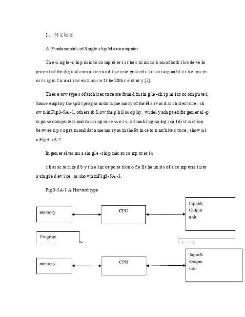
1、外文原文A: Fundamentals of Single-chip MicrocomputerTh e si ng le -c hi p m ic ro co mp ut er i s t he c ul mi na ti on of both t h e de ve lo pm en t of the dig it al com pu te r an d th e in te gr at ed c i rc ui t arg ua bl y t h e tow m os t s ig ni f ic an t i nv en ti on s o f t he 20th c e nt ur y [1].Th es e tow type s of arch it ec tu re are foun d in sin g le -ch i p m i cr oc om pu te r. Som e empl oy the spli t prog ra m/da ta me mo ry of the H a rv ar d ar ch it ect u re , sh ow n in Fig.3-5A -1, oth ers fo ll ow the p h il os op hy , wi del y ada pt ed for gen er al -p ur po se com pu te rs and m i cr op ro ce ss o r s, o f ma ki ng no log i ca l di st in ct ion be tw ee n p r og ra m and dat a me mo ry as in the Pr in ce to n arch ite c tu re , show n i n Fig.3-5A-2.In gen er al ter ms a sin gl e -chi p mic ro co mp ut er i sc h ar ac te ri zed b y t he i nc or po ra ti on of a ll t he un it s of a co mp uter i n to a sin gl e d ev i ce , as sho wn inFi g3-5A -3.Fig.3-5A-1 A Harvard typeFig.3-5A-2. A conventional Princeton computerFig3-5A-3. Principal features of a microcomputerRead only memory (ROM.R OM is usua ll y for the pe rm an ent,n o n-vo la ti le stor a ge of an app lic a ti on s pr og ra m .M an ym i cr oc om pu te rs and m are inte nd e d for high -v ol um e ap pl ic at ions a n d he nc e t h e eco n om ic al man uf act u re of th e de vic e s re qu ir es t h at t he cont en t s o f t he prog ra m me m or y be co mm it t ed perm a ne ntly d u ri ng the man ufa c tu re of ch ip s .Cl ea rl y, thi s im pl ie s a r i go ro us app ro ach to ROM cod e deve l op me nt sin ce cha ng es can not b e mad e afte r manu f a c tu re .Th is dev e lo pm en t proc ess may invo lv e e m ul at io n us in g aso ph is ti ca te d de ve lo pm en t sy ste m wit h a h a rd wa re emu la tio n cap ab il it y as w el l as the use o f po we rf ul s o ft wa re too ls.So me man uf act u re rs pro vi de add it io na l RO M opt i on s by i n cl ud in g in their ra n ge dev ic es wit h (or int en de d fo r use wit h u s er pro gr am ma ble me mo ry. Th e sim p le st of th es e is usu al ly d e vi ce whi ch can op er at e in a micro p ro ce ssor mod e by usi ng som e o f the inp ut /outp u t li ne s as an ad dr es s an d da ta b us fora c ce ss in g ex te rna l mem or y. Thi s t y pe of de vi ce can beh av ef u nc ti on al ly as th e sing le chip mi cr oc om pu te r from whi ch it is d e ri ve d al be it wit h re st ri ct ed I/O and a mod if ied ex te rn al c i rc ui t. The use of thes e d ev ic es is com mo n eve n in prod uc ti on c i rc ui ts wher e t he vo lu me does no tj us ti f y t h e d ev el o pm en t c osts o f c us to m o n -ch i p R OM [2];t he re c a n s ti ll bea s ignif i ca nt saving i n I /O and o th er c h ip s com pa re d to a conv en ti on al mi c ro pr oc es sor b a se d ci rc ui t. Mor e ex ac t re pl ace m en t fo r RO M dev i ce s ca n be o b ta in ed in th e fo rm of va ri an ts w it h 'p ig gy -b ack 'E P RO M(Er as ab le pro gr am ma bl e ROM s oc ke ts or dev ic e s with EPROM i n st ea d o f RO M 。
自动化专业英语原文和翻译
自动化专业英语原文和翻译Title: Original Text and Translation of Automation Professional EnglishIntroduction:In the field of automation, it is essential to have a good command of professional English, as many resources and documents are written in English. In this article, we will explore the original text and translation of automation professional English, providing a comprehensive guide for those looking to improve their language skills in this area.1. Original Text and Translation of Automation Terminology1.1 The original text of automation terminology includes terms such as PLC (Programmable Logic Controller), HMI (Human-Machine Interface), and SCADA (Supervisory Control and Data Acquisition).1.2 The translation of these terms into other languages must be accurate and consistent to ensure clear communication in an international context.1.3 It is important for professionals in the automation industry to be familiar with these terms in both English and their native language to facilitate effective communication with colleagues and clients.2. Original Text and Translation of Automation Standards2.1 Automation standards, such as ISO 9001 and IEC 61131, are crucial for ensuring quality and safety in automation systems.2.2 Translating these standards accurately is essential to ensure compliance with regulations and best practices in different countries.2.3 Professionals in the automation industry should be well-versed in the original text of these standards and their translations to ensure the successful implementation of automation projects worldwide.3. Original Text and Translation of Automation Documentation3.1 Automation documentation, including user manuals, technical specifications, and maintenance guides, is often written in English.3.2 Translating this documentation accurately is essential to ensure that users and technicians can understand and operate automation systems effectively.3.3 Professionals in the automation industry should be proficient in both the original text and translated versions of documentation to facilitate training, troubleshooting, and maintenance of automation systems.4. Original Text and Translation of Automation Research Papers4.1 Research papers on automation topics are often published in English-language journals and conferences.4.2 Translating these papers accurately is crucial for sharing knowledge and advancements in the field of automation with a global audience.4.3 Professionals in the automation industry should be able to read and understand original research papers in English and be familiar with translations in other languages to stay informed about the latest developments in the field.5. Original Text and Translation of Automation Software5.1 Automation software, such as CAD (Computer-Aided Design) and CAM (Computer-Aided Manufacturing) programs, often have interfaces and documentation in English.5.2 Translating this software accurately is essential for ensuring that engineers and technicians can use these tools effectively.5.3 Professionals in the automation industry should be proficient in both the original text and translated versions of automation software to maximize their productivity and efficiency in their work.Conclusion:In conclusion, having a good command of professional English in the field of automation is essential for effective communication, compliance with standards, and staying informed about the latest developments. By understanding the original text and translations of automation terminology, standards, documentation, research papers, and software, professionals in the industry can enhance their language skills and excel in their careers.。
自动化专业英语原文和翻译
自动化专业英语原文和翻译Automation in the Field of EngineeringIntroduction:Automation plays a crucial role in various industries, and the field of engineering is no exception. In this document, we will explore the importance of automation in engineering and its impact on various aspects of the industry. We will also provide a detailed analysis of the benefits and challenges associated with automation in engineering. Additionally, we will discuss the significance of specialized English language skills in the automation profession and provide a translated version of the content in Chinese.Importance of Automation in Engineering:Automation has revolutionized the engineering industry by enhancing productivity, efficiency, and accuracy. It involves the use of advanced technologies and systems to control and monitor various engineering processes. Automation enables engineers to streamline operations, reduce manual labor, and improve overall performance. It plays a vital role in areas such as manufacturing, construction, energy, transportation, and telecommunications.Benefits of Automation in Engineering:1. Increased Productivity: Automation eliminates repetitive and mundane tasks, allowing engineers to focus on more complex and strategic activities. This leads to increased productivity and faster project completion.2. Improved Efficiency: Automated systems can perform tasks more efficiently than humans, resulting in reduced errors and improved quality of work.3. Enhanced Safety: Automation reduces the risk of accidents and injuries by replacing manual labor with machines in hazardous environments.4. Cost Savings: By automating processes, companies can reduce labor costs, minimize waste, and optimize resource utilization, leading to significant cost savings.5. Better Decision-Making: Automation provides engineers with real-time data and analytics, enabling them to make informed decisions and optimize processes for better outcomes.Challenges of Automation in Engineering:1. Initial Investment: Implementing automation systems requires a significant upfront investment in technology, infrastructure, and training.2. Technological Complexity: Automation involves advanced technologies such as robotics, artificial intelligence, and machine learning, which require specialized knowledge and expertise to operate and maintain.3. Workforce Adaptability: Automation may lead to job displacement and require the workforce to acquire new skills to adapt to the changing industry landscape.4. Cybersecurity Risks: With increased reliance on interconnected systems, the risk of cyber threats and data breaches becomes a significant concern in automated engineering environments.Importance of Specialized English Language Skills in Automation:English language proficiency is crucial for professionals in the automation field due to the global nature of the industry. Engineers need to communicate effectively with colleagues, clients, and stakeholders from different countries. Additionally, technical documentation, research papers, and industry standards are often written in English. Proficiency in specialized English terminology related to automation is essential for clear and accurate communication.Translation in Chinese (简体中文翻译):工程自动化的重要性:自动化在各个行业中都发挥着重要作用,工程领域也不例外。
(自动化专业)毕业论文文献翻译中英文对照
(自动化专业)毕业论文文献翻译中英文对照毕业设计外文资料翻译题目可编程控制器技术讨论与未来发展专业电气工程及其自动化PLC technique discussion and future developmentK. Begain, M. ErmelChair for Telecommunications, Dresden University of Technology,01062 Dresden, GermanyAbstract: Programmable Logic Controllers (PLC), a computing device invented by Richard E.Morley in 1968, have been widely used in industry including manufacturing systems, transportation systems, chemical process facilities, and many others. At that time, the PLC placed the hardwired logic with soft-wired logic or so-called relay ladder logic(RLL), a programming language visually resembling the hardwired logic, and reduced thereby the configuration time from 6 months down to 6 days [Moody and Morley,1999].Although PC based control has started to come into place, PLC based control will remain the technique to which the majority of industrial applications will adhere due to its higher performance, lower price, and superior reliability in harsh environments. Moreover, according to a study on the PLC market of Frost and Sullivan [1995], an increase of the annual sales volume to 15 million PLCs per year with the hardware value of more than 8 billion US dollars has been predicted, though the prices of computing hardware is steadily dropping. The inventor of the PLC, Richard E Morley, fairly considers the PLC market as a 5-billion industry at the present time.Key Words:PLC ,performance ,market1 IntroductionAlong with the development of the ages, the technique that is nowadays is also gradually perfect, the competition plays more more strong; the operation that list depends the artificial has already can't satisfied with the current manufacturing industry foreground, also can't guarantee the request of the higher quantity and high new the image of the technique business enterprise.The people see in produce practice, automate brought the tremendous convenience and the product quantities for people up of assurance, also eased the personnel's labor strength, reduce the establishment on the personnel. The target control of the hard realization in many complicated production lines, whole and excellent turn, the best decision etc., well-trained operation work, technical personnel or expert, governor but can judge and operate easily, can acquire the satisfied result. The research target of the artificial intelligence makes use of the calculator exactly to carry out, imitate these intelligences behavior, moderating the work through person's brain and calculators, with the mode that person's machine combine, for resolve the very complicated problem to look for the best pathWe come in sight of the control that links after the electric appliances in various situation, that is already the that time generation past, now of after use in the mold a perhaps simple equipments of grass-roots control that the electric appliances can do for the low level only;And the PLC emergence also became the epoch-making topic, adding the vivid software control through a very and stable hardware, making the automation head for the new high tide.2 PLC characteristics and containment2.1 The PLC biggest characteristicsThe PLC biggest characteristics lie in: The electrical engineering teacher already no longer electric hardware up too many calculationses of cost, as long as order the importation that the button switch or the importation of the sensors order to link the PLC up can solve problem, pass to output to order the conjunction contact machine or control the start equipments of the big power after the electric appliances, but the exportation equipments direct conjunction of the small power can.Figure 1. Open frame PLC2.2 PLC internal containmentPLC internal containment have CPU, and take to have an I/ O for expand of exterior to connect a people's address and saving machine three big pieces to constitute, CPU core is from an or many is tired to add the machine to constitute, mathematics that they have the logic operation ability, and can read the procedure save the contents of the machine to drive the homologous saving machine and I/ Os to connect after pass the calculation; The I/ O add inner part is tired the input and output system of the machine and exterior link, and deposit the related data into the procedure saving machine or data saving machine; The saving machine can deposit the data that the I/ O input in the saving machine, and in work adjusting to become tired to add the machine and I/ Os to connect, saving machine separately saving machine RAM of the procedure saving machine ROM and datas, the ROM can can do deposit of the data permanence in the saving machine, but RAM only for the CPU computes the temporary calculation usage of hour of buffer space.Figure 2. PLC input and output circuits2.3 PLC advantageThe PLC anti- interference is very and excellent, our root need not concern its service life and the work situation bad, these all problems have already no longer become the topic that we fail, but stay to our is a concern to come to internal resources of make use of the PLC to strengthen the control ability of the equipments for us, make our equipments more gentle.PLC language is not we imagine of edit collected materials the language or language of Cs to carry on weaving the distance, but the trapezoid diagram that the adoption is original after the electric appliances to control, make the electrical engineering teacher while weaving to write the procedure very easy comprehended the PLC language, and a lot of non- electricity professional also very quickly know and go deep into to the PLC.3 HMIIs PLC one of the advantage above and only, this is also one part that the people comprehend more and easily, in a lot of equipmentses, the people have already no longer hoped to see too many control buttons, they damage not only and easily and produce the artificial error easiest, small is not a main error perhaps you can still accept; But lead even is a fatal error greatly is what we can't is tolerant of. New technique always for bringing more safe and convenient operation for us, make we a lot of problems for face on sweep but light, do you understand the HMI? Says the HMI here you basically not clear what it is, also have no interest understanding, change one inside text explains it into the touch to hold or man-machine interface you knew, it combines with the PLC to our larger space.HMI the control not only only is reduced the control press button, increase the vivid of the control, more main of it is can sequence of, and at can the change data input to output the feedback with data, control in the temperature curve of imitate but also can keep the manifestation of view to come out. And can write the function help procedure through a plait to provide the help of various what lies in one's power, the one who make operate reduces the otiose error. Currently the HMI factory is also more and more, the function is also more and more strong, the price is also more and more low, the noodles of the usage are wide more and more. The HMI foreground can say that think ° to be good very.4 PLC correspondence and data transmissionAt a lot of situations, the list is is a smooth movement that can't guarantee theequipments by the control of the single machine, but pass the information exchanges of the equipments and equipments to attain the result that we want. For example fore pack and the examination of the empress work preface, we will arrive wrapping information feedback to examine the place, and examine the information of the place to also want the feedback to packing. Pass the information share thus to make both the chain connect, becoming a total body, the match of your that thus make is more close, at each other attain to reflect the result that mutually flick.The PLC correspondence has already come more more body now its value, at the PLC and correspondence between PLCs, can pass the communication of the information and the share of the datas to guarantee that of the equipments moderates mutually, the result that arrive already to repair with each other. Data conversion the adoption RS232 between PLC connect to come to the transmission data, but the RS232 pick up a people and can guarantee 10 meters only of deliver the distance, if in the distance of 1000 meters we can pass the RS485 to carry on the correspondence, the longer distance can pass the MODEL only to carry on deliver.The PLC data transmission is just to be called a form to it in a piece of and continuous address that the data of the inner part delivers the other party, we, the PLC of the other party passes to read data in the watch to carry on the operation. If the data that data in the watch is a to establish generally, that is just the general data transmission, for example today of oil price rise, I want to deliver the price of the oil price to lose the oil ally on board, that is the share of the data; But take data in the watch for an instruction procedure that controls the PLC, that had the difficulty very much, for example you have to control one pedestal robot to press the action work that you imagine, you will draw up for it the form that a procedure combine with the data sends out to pass by.Figure 3. PLC connection with experiments board.4.1 Form of information transmission4.1.1 Simplex and DuplexThe form that information transport contain Simplex, the Half duplex and the Full duplex.The meaning of the Simplex also is to say both, a can send out only, but a can receive only, for example a spy he can receive the designation of the superior only, but can't give the superior reply; Half duplex is also 2 and can can send out similar to accept the data, but can't send out and accept at the same time, for example when you make a phone call is to can't answer the phone, the other party also; But the Half duplex is both can send out and accept the data, and can send out and accept at the same time. Be like the Internet is a typical example.4.1.2 Synchronous and AsynchronousThe process that information transport also has synchronous and asynchronous: The data line and the clock lines are synchronous when synchronous meaning lie in sending out the data, is also the data signal and the clock signals to be carry on by the CPU to send out at the same time, this needs to all want the specialized clock signal each other to carry on the transmission and connect to send, and is constrained, the characteristics of this kind of method lies in its speed very quick, but correspond work time of take up the CPU and also want to be long oppositely, at the same time the technique difficulty also very big. Itsrequest lies in can'ting have an error margins in a datas deliver, otherwise the whole pieceaccording to compare the occurrence mistake, this on the hardware is a bigger difficulty. Applied more and more extensive in some appropriative equipmentses, be like the appropriative medical treatment equipments, the numerical signal equipments...etc., in compare the one data deliver, its result is very good.And asynchronous is an application the most extensive, this receive benefit in it of technique difficulty is opposite and want to be small, at the same time not need to prepare the specialized clock signal, its characteristics to lie in, its data is partition, the long-lost send out and accept, be the CPU is too busy of time can grind to a stop sex to work, also reduced the difficulty on the hardware, the data throw to lose at the same time opposite want to be little, we can pass the examination of the data to observe whether the data that we send out has the mistake or not, be like strange accidentally the method, tired addition and eight efficacies method etc., can use to helps whether the data that we examine to send out have or not the mistake occurrence, pass the feedback to carry on the discriminator.4.1.3 Parallel and SerialA line of transmission of the information contain a string of and combine the cent of: The usual PLC is 8 machines, certainly also having 16 machines. We can be an at the time of sending out the data a send out to the other party, also can be 88 send out the data to the other party, an and 8 differentiationses are also the as that we say to send out the data and combine sends out the data. A speed is more and slowly, but as long as 2 or three lines can solve problem, and can use the telephone line to carry on the long range control. But combine the oscular transmission speed is very quick of, it is a string of oscular of 25600%, occupy the advantage in the short distance, the in view of the fact TTL electricity is even, being limited by the scope of one meter generally, it combine unwell used for the data transmission of the long pull, thus the cost is too expensive.Under a lot of circumstances we are total to like to adopt the string to combine the conversion chip to carry on deliver, under this kind of circumstance not need us to carry on to depositted the machine to establish too and complicatedly, but carry on the data exchanges through the data transmission instruction directly, but is not a very viable way in the correspondence, because the PLC of the other party must has been wait for your data exportation at the time of sending out the data, it can't do other works.4.2 InterruptWhen you are reading the book, you hear someone knock on door, you stop to start up of affair, open the door and combine to continue with the one who knock on door a dialogue, the telephone of this time rang, you signal hint to connect a telephone, afterconnecting the telephone through, return overdo come together knock on door to have a conversation, after dialogue complete, you continue again to see your book, this kind of circumstance we are called the interruption to it, it has the authority, also having sex of have the initiative, the PLC had such function .Its characteristics lie in us and may meet the urgently abrupt affairs in the operation process of the equipments, we want to stop to start immediately up of work, the whereabouts manages the more important affair, this kind of circumstance is we usually meet of, PLC while carry out urgent mission, total will keep the current appearance first, for example the address of the procedure, CPU of tired add the machine data etc., be like to to stick down which the book that we see is when we open the door the page or simply make a mark, because we treat and would still need to continue immediately after book of see the behind. The CPU always does the affair that should do according to our will, but your mistake of give it an affair, it also would be same to do, this we must notice.The interruption is not only a, sometimes existing jointly with the hour several inside break, break off to have the preferred Class, they will carry out the interruption of the higher Class according to person's request. This kind of breaks off the medium interruption to also became to break off the set. The Class that certainly break off is relevant according to various resources of CPU with internal PLC, also following a heap of capacity size of also relevant fasten.The contents that break off has a lot of kinds, for example the exterior break off, correspondence in of send out and accept the interruption and settle and the clock that count break off, still have the WDT to reset the interruption etc., they enriched the CPU to respond to the category while handle various business. Speak thus perhaps you can't comprehend the internal structure and operation orders of the interruption completely also, we do a very small example to explain.4.3 Emergency stop buttonEach equipments always will not forget a button, it also is at we meet the urgent circumstance use of, that is nasty to stop the button. When we meet the Human body trouble and surprised circumstances we as long as press it, the machine stops all operations immediately, and wait for processing the over surprised empress recover the operation again.Nasty stop the internal I/ O of the internal CPU of the button conjunction PLC to connect up, be to press button an exterior to trigger signal for CPU, the CPU carries on to the I/ O to examine again, being to confirm to have the exterior to trigger the signal, CPU protection the spot breaks off procedure counts the machine turn the homologous exteriorI/ O automatically in the procedure to go to also, be exterior interruption procedure processing complete, the procedure counts the machine to return the main procedure to continue to work.Have 1:00 can what to explain is we generally would nasty stop the button of exterior break off to rise to the tallest Class, thus guarantee the safety.4.4 PLC Counting functionWhen we are work a work piece, giving the PLC a signal, counting PLC inner part the machine add 1 to compute us for a day of workload, a count the machine and can solve problem in brief, certainly they also can keep the data under the condition of dropping the electricity, urging the data not to throw to lose, this is also what we hope earnestly.The PLC still has the function that the high class counts the machine, being us while accept some datas of high speed, the high speed that here say is the data of the in all aspects tiny second class, for example the bar code scanner is scanning the data continuously, calculating high-speed signal of the data processor DSP etc., we will adopt the high class to count the machine to help we carry on count. It at the PLC carries out the procedure once discover that the high class counts the machine to should of interruption, will let go of the work on the hand immediately. The trapezoid diagram procedure that passes by to weave the distance again explains the high class for us to carry out procedure to count machine would automatic performance to should of work, thus rise the Class that the high class counts the machine to high one Class.You heard too many this phrases perhaps:" crash", the meaning that is mostly is a workload of CPU to lead greatly, the internal resources shortage etc. the circumstance can't result in procedure circulate. The PLC also has the similar circumstance, there is a watchdog WDT in the inner part of PLC, we can establish time that a procedure of WDT circulate, being to appear the procedure to jump to turn the mistake in the procedure movement process or the procedure is busy, movement time of the procedure exceeds WDT constitution time, the CPU turn but the WDT reset the appearance. The procedure restarts the movement, but will not carry on the breakage to the interruption.Figure 4. Overall board design.5 PLC development in the futureThe PLC development has already entered for network ages of correspondence from the mode of the one, and together other works control the net plank and I/ O card planks to carry on the share easily. A state software can pass all se hardwares link, more animation picture of keep the view to carries on the control, and cans pass the Internet to carry on the control in the foreign land, the blast-off that is like the absolute being boat No.5 is to adopt this kind of way to make airship go up the sky.The development of the higher layer needs our continuous effort to obtain.The PLC emergence has already affected a few persons fully, we also obtained more knowledge and precepts from the top one experience of the generation, coming to the continuous development PLC technique, push it toward higher wave tide.References[1] R. Alur, C. Courcoubetis, and D. Dill. Model-Checking for Real-Time Systems.In Fifth Annual IEEE Symp. on Logic in Computer Science, pages 414{425.IEEE Press, 1990. [2] R. Alur and D.L. Dill. A theory of timed automata. Theoret. Comput. Sci.,126:183{235, 1994.[3] R. Alur, T. Henzinger, and E. Sontag, editors. Hybrid Systems III, volume 1066 of Lecture Notes in Computer Science. Springer-Verlag, 1996.[4] J. Bengtsson, K.G. Larsen, F. Larsson, P. Pettersson, and Wang Yi. Uppaal {a ToolSuite for Automatic Verification of Real-Time Systems. In Alur et al.[3]. 232{243.[5] D. Bosscher, I. Polak, and F. Vaandrager. Verification of an Audio Control Protocol. InH. Langmaack, W.-P. de Roever, and J. Vytopil, editors, Formal Techniques in Real-Time and Fault-Tolerant Systems, volume 863 of Lecture Notes in Computer Science, pages 170{192. Springer-Verlag, 1994.PLC technique discussion and future development, 2010, 130(9): 2436-2443.可编程控制器技术讨论与未来发展K.培根, M. 厄米尔通信教授, 德累斯顿科技大学,01062德累斯顿,德国摘要可编程逻辑控制器(PLC)是Richard E.Morley在1968年发明的一种具备运算功能的设备,现已被广泛的应用到工业中,包括制造系统、交通系统、化工过程设备等。
自动化专业单片机相关外文文献英文文献外文翻译中英对照
使用本科生毕业论文V外文翻译)译文名称:MCS -51系列单片机地功能和结构专业:自动化班次:学员:指导教员:评阅人:完成时间:2018年11月30日Structure and function of the MCS-51 seriesStructure and function of the MCS-51 series one-chip computer is a name of a piece of on e-chip computer series which In tel Compa ny produces. This compa ny in troduced 8 top-grade on e-chip computers of MCS-51 series in 1980 after introducing 8 one-chip computers of MCS-48 series in 1976. It belong to a lot of kinds this line of on e-chip computer the chips have,such as 8051,8031, 8751, 80C51BH, 80C31BH,etc., their basic composition, basic performance and in structi on system are all the same. 8051 daily represe ntatives-51 serial on e-chip computers b5E2RGbCAPAn one-chip computer system is made up of several following parts: ( 1> One microprocessor of 8 (CPU>. ( 2> At slice data memory RAM (128B/256B>,it use not depositting not can reading /data that write, such as result not middle of operati on, final result and data wan ted to show, etc. ( 3> Procedure memory ROM/EPROM (4KB/8KB >, is used to preserve the procedure , some initial data and form in slice. But does not take ROM/EPROM within some on e-chip computers, such as 8031 , 8032, 80C ,etc.. (4> Four 8 run side by side I/O in terface P0 four P3, each mouth can use as introduction , may use as exporting too. ( 5> Two timer / counter, each timer / coun ter may set up and count in the way, used to count to the exter nal in cide nt, can set up into a timing way too, and can according to count or result of timing realize the control of the computer. ( 6> Five cut off cutting off the control system of the source . ( 7> One all duplexing serial I/O mouth of UART (uni versal asynchronous receiver/tra nsmitter (UART> >, is it realize on e-chip computer or on e-chip computer and serial com muni catio n of computer to use for. ( 8> Stretch oscillator and clock produce circuit, quartz crystal finely tune electric capacity n eed outer. Allow oscillati on freque ncy as 12 megahertas now at most. Every the above-me nti oned part was joined through the in side data bus .Among them, CPU is a core of the one-chip computer, it is the control of the computer and comma nd cen tre, made up of such parts as arithmeticunit and使用controller , etc.. The arithmetic unit can carry on 8 persons of arithmetic operation and unit ALU of logic operation while including one, the 1 storing device temporarilies of 8, stori ng device 2 temporarily, 8's accumulatio n device ACC, register B and procedure stateregister PSW, etc. Pers on who accumulate ACC count by 2 in put ends en tered of check ing etc. temporarily as one operation often, come from person who store 1 operation is it is it make operation to go on to count temporarily , operation result and loopback ACC withanother one. In addition, ACC is often regarded as the transfer station of data tran smissi on on 8051 in side . The same as gen eral microprocessor, it is the busiest register. Help rememberi ng that agree ing with A expresses in the order. The con troller in cludes the procedure coun ter , the order is depositted, the order decipher, the oscillator and timing circuit, etc. The procedure counter is made up of coun ter of 8 for two, amounts to 16. Itis a byte address coun ter of the procedure in fact, the content is the next IA that will carried out in PC. The content which cha nges it can cha nge the directi on that the procedure carries out . Shake the circuit in 8051 one-chip computers, only need outer quartz crystal and freque ncy to fin ely tune the electric capacity, its freque ncy range is its12MHZ of 1.2MHZ. This pulse signal, as 8051 basic beats of working, namely the minimum unit of time. 8051 is the same as other computers, the work in harmony under the control of the basic beat, just like an orchestra accord ing to the beat play that is comma nded&nqFDPw There are ROM (procedure memory , can only read > and RAM in 8051 slices (data memory, can is it can write > two to read, they have each in depe ndent memory address space, dispose way to be the same with gen eral memory of computer. Procedure 8051 memory and 8751 slice procedure memory capacity 4KB, address begin from 0000H, used for preserving the procedure and form con sta nt. Data 8051- 8751 8031 of memory data memory 128B, address false 00FH, use for middle result to deposit operation, the data are stored temporarily and the data are buffered etc.. In RAM of this 128B,使用there is unit of 32 byteses that can be appo in ted as the job register, this and gen eral microprocessor is differe nt, 8051 slice RAM and job register rank one formation the same to arrange the location. It is not very the same that the memory of MCS-51 series one-chip computer and general computer disposes the way in additi on. Gen eral computer for first address space, ROM and RAM can arrange in differe nt space with in the range of this address at will, n amely the addresses of ROM and RAM, with distributing different address space ina formation. While visiting the memory, corresponding and only an address Memory unit, canROM, it can be RAM too, and by visiting the order similarly. This kind of memory structure is called the structure of Princeton. 8051 memories are divided into procedure memory space and data memory space on the physics structure, there are four memory spaces in all: The procedure stores in one and data memory space outside data memory and one in procedure memory space and one outside one, the structure forms of this kind of procedure device and data memory separated form data memory, called Harvard structure. But use the an gle from users, 8051 memory address space is divided into three kin ds: (1> In the slice, arrange blocks of FFFFH , 0000H of locati on , in unison outside the slice (use 16 addresses>. (2> The data memory address space outside one of 64KB, the address is arran ged from 0000H 64KB FFFFH (with 16 addresses> too to the location. (3> Data memory address space of 256B (use 8 addresses>. Three above-mentioned memory space addresses overlap, for distinguishing and designing the order symbol of different data transmission in the instruction system of 8051: CPU visit slice, ROM order spend MOVC , visit block RAM order uses MOVX outside the slice, RAM order uses MOV to visit in slice. DXDiTa9E3d8051 one-chip computer have four 8 walk abreast I/O port, call P0, P1, P2 and P3. Each port is 8 accurate two-way mouths, accounts for 32 pins altogether. Every one I/O line can be used as introduction and exported in depe nden tly. Each port in cludes a latch (n amely special fun cti on register >,使用one exports the driver and a introduction buffer . Make data can latch when outputting, data can buffer when making introduction , but four function of passway these self-same. Expa nd among the system of memory outside hav ing slice, four port these may serve as accurate two-way mouth of I/O in com mon use. Expand among the system of memory outside having slice, P2 mouth see high 8 address off= P0 mouth is a two-way bus, send the in troduct ion of 8 low addresses and data / export in timesharingr crpuDGiTThe circuit of 8051 on e-chip computers and four I/O ports is very ingenious in design. Familiar with I/O port logical circuit, not only help to use ports correctly and rati on ally, and will in spire to desig ning the peripheral logical circuit of on e-chip computer to some exte nt. Load ability and in terface of port have certa in requireme nt, because output grade, P0 of mouth and P1 end output, P3 of mouth grade differe nt at structure, so,the load ability and in terface of its door dema nd to have nothing in com mon with each other. P0 mouth is differe nt from other mouths, its output grade draws the resistance supremly. When using it as the mouth in com mon use to use, output grade is it leak circuit to turn on, is it is it urge NMOS draw the resistance on taking to be outer with it while in putt ing to go out to fail. When being used as in troductio n, should write "1" to a latch first. Every one with P0 mouth can drive 8 Model LS TTL load to export. P1 mouth is an accurate two-way mouth too, used as I/O in com mon use. Different from P0 mouth output of circuit its, draw load resistance link with power on in side have. In fact, the resista nce is that two effects are in charge of FET and together: One FET is in charge of load, its resistance is regular. Another one can is it lead to work with close at two state, make its Preside nt resista nce value cha nge approximate 0 or group value heavy two situation very. When it is 0 that the resistance is approximate , can draw the pin to the high level fast。
电气工程与自动化毕业论文中英文资料外文翻译
电气工程与自动化毕业论文中英文资料外文翻译The Transformer on load ﹠Introduction to DC MachinesIt has been shown that a primary input voltage 1V can be transformed to any desired open-circuit secondary voltage 2E by a suitable choice of turns ratio. 2E is available for circulating a load current impedance. For the moment, a lagging power factor will be considered. The secondary current and the resulting ampere-turns 22N I will change the flux, tending to demagnetize the core, reduce m Φ and with it 1E . Because the primary leakage impedance drop is so low, a small alteration to 1Ewill cause an appreciable increase of primary current from 0I to a new value of 1Iequal to ()()i jX R E V ++111/. The extra primary current and ampere-turns nearly cancel the whole of the secondary ampere-turns. This being so , the mutual flux suffers only a slight modification and requires practically the same net ampere-turns 10N I as on no load. The total primary ampere-turns are increased by an amount 22N I necessary to neutralize the same amount of secondary ampere-turns. In thevector equation , 102211N I N I N I =+; alternatively, 221011N I N I N I -=. At full load,the current 0I is only about 5% of the full-load current and so 1I is nearly equalto 122/N N I . Because in mind that 2121/N N E E =, the input kV A which is approximately 11I E is also approximately equal to the output kV A, 22I E .The physical current has increased, and with in the primary leakage flux towhich it is proportional. The total flux linking the primary ,111Φ=Φ+Φ=Φm p , isshown unchanged because the total back e.m.f.,(dt d N E /111Φ-)is still equal and opposite to 1V . However, there has been a redistribution of flux and the mutual component has fallen due to the increase of 1Φ with 1I . Although the change is small, the secondary demand could not be met without a mutual flux and e.m.f.alteration to permit primary current to change. The net flux s Φlinking thesecondary winding has been further reduced by the establishment of secondaryleakage flux due to 2I , and this opposes m Φ. Although m Φ and 2Φ are indicatedseparately , they combine to one resultant in the core which will be downwards at theinstant shown. Thus the secondary terminal voltage is reduced to dt d N V S /22Φ-=which can be considered in two components, i.e. dt d N dt d N V m //2222Φ-Φ-=orvectorially 2222I jX E V -=. As for the primary, 2Φ is responsible for a substantiallyconstant secondary leakage inductance222222/Λ=ΦN i N . It will be noticed that the primary leakage flux is responsible for part of the change in the secondary terminal voltage due to its effects on the mutual flux. The two leakage fluxes are closely related; 2Φ, for example, by its demagnetizing action on m Φ has caused the changes on the primary side which led to the establishment of primary leakage flux.If a low enough leading power factor is considered, the total secondary flux and the mutual flux are increased causing the secondary terminal voltage to rise with load. p Φ is unchanged in magnitude from the no load condition since, neglecting resistance, it still has to provide a total back e.m.f. equal to 1V . It is virtually the same as 11Φ, though now produced by the combined effect of primary and secondary ampere-turns. The mutual flux must still change with load to give a change of 1E and permit more primary current to flow. 1E has increased this time but due to the vector combination with 1V there is still an increase of primary current.Two more points should be made about the figures. Firstly, a unity turns ratio has been assumed for convenience so that '21E E =. Secondly, the physical picture is drawn for a different instant of time from the vector diagrams which show 0=Φm , if the horizontal axis is taken as usual, to be the zero time reference. There are instants in the cycle when primary leakage flux is zero, when the secondary leakage flux is zero, and when primary and secondary leakage flux is zero, and when primary and secondary leakage fluxes are in the same sense.The equivalent circuit already derived for the transformer with the secondary terminals open, can easily be extended to cover the loaded secondary by the addition of the secondary resistance and leakage reactance.Practically all transformers have a turns ratio different from unity although such an arrangement is sometimes employed for the purposes of electrically isolating one circuit from another operating at the same voltage. To explain the case where 21N N ≠ the reaction of the secondary will be viewed from the primary winding. The reaction is experienced only in terms of the magnetizing force due to the secondary ampere-turns. There is no way of detecting from the primary side whether 2I is large and 2N small or vice versa, it is the product of current and turns which causesthe reaction. Consequently, a secondary winding can be replaced by any number of different equivalent windings and load circuits which will give rise to an identical reaction on the primary .It is clearly convenient to change the secondary winding to an equivalent winding having the same number of turns 1N as the primary.With 2N changes to 1N , since the e.m.f.s are proportional to turns, 2212)/('E N N E = which is the same as 1E .For current, since the reaction ampere turns must be unchanged 1222'''N I N I = must be equal to 22N I .i.e. 2122)/(I N N I =.For impedance , since any secondary voltage V becomes V N N )/(21, and secondary current I becomes I N N )/(12, then any secondary impedance, including load impedance, must becomeI V N N I V /)/('/'221=. Consequently,22212)/('R N N R = and 22212)/('X N N X = . If the primary turns are taken as reference turns, the process is called referring to the primary side.There are a few checks which can be made to see if the procedure outlined is valid.For example, the copper loss in the referred secondary winding must be the same as in the original secondary otherwise the primary would have to supply a differentloss power. ''222R I must be equal to 222R I . )222122122/()/(N N R N N I •• does infact reduce to 222R I .Similarly the stored magnetic energy in the leakage field)2/1(2LI which is proportional to 22'X I will be found to check as ''22X I . The referred secondary 2212221222)/()/(''I E N N I N N E I E kVA =•==.The argument is sound, though at first it may have seemed suspect. In fact, if the actual secondary winding was removed physically from the core and replaced by the equivalent winding and load circuit designed to give the parameters 1N ,'2R ,'2X and '2I , measurements from the primary terminals would be unable to detect any difference in secondary ampere-turns, kVA demand or copper loss, under normal power frequency operation.There is no point in choosing any basis other than equal turns on primary andreferred secondary, but it is sometimes convenient to refer the primary to the secondary winding. In this case, if all the subscript 1’s are interchanged for the subscript 2’s, the necessary referring constants are easily found; e.g. 2'1R R ≈,21'X X ≈; similarly 1'2R R ≈ and 12'X X ≈.The equivalent circuit for the general case where 21N N ≠ except that m r hasbeen added to allow for iron loss and an ideal lossless transformation has been included before the secondary terminals to return '2V to 2V .All calculations of internal voltage and power losses are made before this ideal transformation is applied. The behaviour of a transformer as detected at both sets of terminals is the same as the behaviour detected at the corresponding terminals of this circuit when the appropriate parameters are inserted. The slightly different representation showing the coils 1N and 2N side by side with a core in between is only used for convenience. On the transformer itself, the coils are , of course , wound round the same core.Very little error is introduced if the magnetising branch is transferred to the primary terminals, but a few anomalies will arise. For example ,the current shown flowing through the primary impedance is no longer the whole of the primary current.The error is quite small since 0I is usually such a small fraction of 1I . Slightlydifferent answers may be obtained to a particular problem depending on whether or not allowance is made for this error. With this simplified circuit, the primary and referred secondary impedances can be added to give:221211)/(Re N N R R += and 221211)/(N N X X Xe +=It should be pointed out that the equivalent circuit as derived here is only valid for normal operation at power frequencies; capacitance effects must be taken into account whenever the rate of change of voltage would give rise to appreciablecapacitance currents, dt CdV I c /=. They are important at high voltages and atfrequencies much beyond 100 cycles/sec. A further point is not the only possible equivalent circuit even for power frequencies .An alternative , treating the transformer as a three-or four-terminal network, gives rise to a representation which is just as accurate and has some advantages for the circuit engineer who treats all devices as circuit elements with certain transfer properties. The circuit on this basiswould have a turns ratio having a phase shift as well as a magnitude change, and the impedances would not be the same as those of the windings. The circuit would not explain the phenomena within the device like the effects of saturation, so for an understanding of internal behaviour .There are two ways of looking at the equivalent circuit:(a) viewed from the primary as a sink but the referred load impedance connected across '2V ,or(b) viewed from the secondary as a source of constant voltage 1V with internal drops due to 1Re and 1Xe . The magnetizing branch is sometimes omitted in this representation and so the circuit reduces to a generator producing a constant voltage 1E (actually equal to 1V ) and having an internal impedance jX R + (actually equal to 11Re jXe +).In either case, the parameters could be referred to the secondary winding and this may save calculation time .The resistances and reactances can be obtained from two simple light load tests. Introduction to DC MachinesDC machines are characterized by their versatility. By means of various combination of shunt, series, and separately excited field windings they can be designed to display a wide variety of volt-ampere or speed-torque characteristics for both dynamic and steadystate operation. Because of the ease with which they can be controlled , systems of DC machines are often used in applications requiring a wide range of motor speeds or precise control of motor output.The essential features of a DC machine are shown schematically. The stator has salient poles and is excited by one or more field coils. The air-gap flux distribution created by the field winding is symmetrical about the centerline of the field poles. This axis is called the field axis or direct axis.As we know , the AC voltage generated in each rotating armature coil is converted to DC in the external armature terminals by means of a rotating commutator and stationary brushes to which the armature leads are connected. The commutator-brush combination forms a mechanical rectifier, resulting in a DCarmature voltage as well as an armature m.m.f. wave which is fixed in space. The brushes are located so that commutation occurs when the coil sides are in the neutral zone , midway between the field poles. The axis of the armature m.m.f. wave then in 90 electrical degrees from the axis of the field poles, i.e., in the quadrature axis. In the schematic representation the brushes are shown in quarature axis because this is the position of the coils to which they are connected. The armature m.m.f. wave then is along the brush axis as shown.. (The geometrical position of the brushes in an actual machine is approximately 90 electrical degrees from their position in the schematic diagram because of the shape of the end connections to the commutator.)The magnetic torque and the speed voltage appearing at the brushes are independent of the spatial waveform of the flux distribution; for convenience we shall continue to assume a sinusoidal flux-density wave in the air gap. The torque can then be found from the magnetic field viewpoint.The torque can be expressed in terms of the interaction of the direct-axis air-gapflux per pole d Φ and the space-fundamental component 1a F of the armature m.m.f.wave . With the brushes in the quadrature axis, the angle between these fields is 90 electrical degrees, and its sine equals unity. For a P pole machine 12)2(2a d F P T ϕπ=In which the minus sign has been dropped because the positive direction of thetorque can be determined from physical reasoning. The space fundamental 1a F ofthe sawtooth armature m.m.f. wave is 8/2π times its peak. Substitution in above equation then givesa d a a d a i K i m PC T ϕϕπ==2 Where a i =current in external armature circuit;a C =total number of conductors in armature winding;m =number of parallel paths through winding;Andm PC K aa π2=Is a constant fixed by the design of the winding.The rectified voltage generated in the armature has already been discussedbefore for an elementary single-coil armature. The effect of distributing the winding in several slots is shown in figure ,in which each of the rectified sine waves is the voltage generated in one of the coils, commutation taking place at the moment when the coil sides are in the neutral zone. The generated voltage as observed from the brushes is the sum of the rectified voltages of all the coils in series between brushesand is shown by the rippling line labeled a e in figure. With a dozen or socommutator segments per pole, the ripple becomes very small and the average generated voltage observed from the brushes equals the sum of the average values ofthe rectified coil voltages. The rectified voltage a e between brushes, known also asthe speed voltage, ism d a m d a a W K W m PC e ϕϕπ==2 Where a K is the design constant. The rectified voltage of a distributed winding has the same average value as that of a concentrated coil. The difference is that the ripple is greatly reduced.From the above equations, with all variable expressed in SI units:m a a Tw i e =This equation simply says that the instantaneous electric power associated with the speed voltage equals the instantaneous mechanical power associated with the magnetic torque , the direction of power flow being determined by whether the machine is acting as a motor or generator.The direct-axis air-gap flux is produced by the combined m.m.f. f f i N ∑ of the field windings, the flux-m.m.f. characteristic being the magnetization curve for the particular iron geometry of the machine. In the magnetization curve, it is assumed that the armature m.m.f. wave is perpendicular to the field axis. It will be necessary to reexamine this assumption later in this chapter, where the effects of saturation are investigated more thoroughly. Because the armature e.m.f. is proportional to flux times speed, it is usually more convenient to express the magnetization curve in termsof the armature e.m.f. 0a e at a constant speed 0m w . The voltage a e for a given fluxat any other speed m w is proportional to the speed,i.e. 00a m m a e w w e =Figure shows the magnetization curve with only one field winding excited. This curve can easily be obtained by test methods, no knowledge of any design details being required.Over a fairly wide range of excitation the reluctance of the iron is negligible compared with that of the air gap. In this region the flux is linearly proportional to the total m.m.f. of the field windings, the constant of proportionality being the direct-axis air-gap permeance.The outstanding advantages of DC machines arise from the wide variety of operating characteristics which can be obtained by selection of the method of excitation of the field windings. The field windings may be separately excited from an external DC source, or they may be self-excited; i.e., the machine may supply its own excitation. The method of excitation profoundly influences not only the steady-state characteristics, but also the dynamic behavior of the machine in control systems.The connection diagram of a separately excited generator is given. The required field current is a very small fraction of the rated armature current. A small amount of power in the field circuit may control a relatively large amount of power in the armature circuit; i.e., the generator is a power amplifier. Separately excited generators are often used in feedback control systems when control of the armature voltage over a wide range is required. The field windings of self-excited generators may be supplied in three different ways. The field may be connected in series with the armature, resulting in a shunt generator, or the field may be in two sections, one of which is connected in series and the other in shunt with the armature, resulting in a compound generator. With self-excited generators residual magnetism must be present in the machine iron to get the self-excitation process started.In the typical steady-state volt-ampere characteristics, constant-speed primemovers being assumed. The relation between the steady-state generated e.m.f. a Eand the terminal voltage t V isa a a t R I E V -=Where a I is the armature current output and a R is the armature circuitresistance. In a generator, a E is large than t V ; and the electromagnetic torque T is acountertorque opposing rotation.The terminal voltage of a separately excited generator decreases slightly with increase in the load current, principally because of the voltage drop in the armature resistance. The field current of a series generator is the same as the load current, so that the air-gap flux and hence the voltage vary widely with load. As a consequence, series generators are not often used. The voltage of shunt generators drops off somewhat with load. Compound generators are normally connected so that the m.m.f. of the series winding aids that of the shunt winding. The advantage is that through the action of the series winding the flux per pole can increase with load, resulting in a voltage output which is nearly constant. Usually, shunt winding contains many turns of comparatively heavy conductor because it must carry the full armature current of the machine. The voltage of both shunt and compound generators can be controlled over reasonable limits by means of rheostats in the shunt field. Any of the methods of excitation used for generators can also be used for motors. In the typical steady-state speed-torque characteristics, it is assumed that the motor terminals are supplied froma constant-voltage source. In a motor the relation between the e.m.f. a E generated inthe armature and the terminal voltage t V isa a a t R I E V +=Where a I is now the armature current input. The generated e.m.f. a E is nowsmaller than the terminal voltage t V , the armature current is in the oppositedirection to that in a motor, and the electromagnetic torque is in the direction to sustain rotation of the armature.In shunt and separately excited motors the field flux is nearly constant. Consequently, increased torque must be accompanied by a very nearly proportional increase in armature current and hence by a small decrease in counter e.m.f. to allow this increased current through the small armature resistance. Since counter e.m.f. is determined by flux and speed, the speed must drop slightly. Like the squirrel-cage induction motor ,the shunt motor is substantially a constant-speed motor having about 5 percent drop in speed from no load to full load. Starting torque and maximum torque are limited by the armature current that can be commutatedsuccessfully.An outstanding advantage of the shunt motor is ease of speed control. With a rheostat in the shunt-field circuit, the field current and flux per pole can be varied at will, and variation of flux causes the inverse variation of speed to maintain counter e.m.f. approximately equal to the impressed terminal voltage. A maximum speed range of about 4 or 5 to 1 can be obtained by this method, the limitation again being commutating conditions. By variation of the impressed armature voltage, very wide speed ranges can be obtained.In the series motor, increase in load is accompanied by increase in the armature current and m.m.f. and the stator field flux (provided the iron is not completely saturated). Because flux increases with load, speed must drop in order to maintain the balance between impressed voltage and counter e.m.f.; moreover, the increase in armature current caused by increased torque is smaller than in the shunt motor because of the increased flux. The series motor is therefore a varying-speed motor with a markedly drooping speed-load characteristic. For applications requiring heavy torque overloads, this characteristic is particularly advantageous because the corresponding power overloads are held to more reasonable values by the associated speed drops. Very favorable starting characteristics also result from the increase in flux with increased armature current.In the compound motor the series field may be connected either cumulatively, so that its.m.m.f.adds to that of the shunt field, or differentially, so that it opposes. The differential connection is very rarely used. A cumulatively compounded motor has speed-load characteristic intermediate between those of a shunt and a series motor, the drop of speed with load depending on the relative number of ampere-turns in the shunt and series fields. It does not have the disadvantage of very high light-load speed associated with a series motor, but it retains to a considerable degree the advantages of series excitation.The application advantages of DC machines lie in the variety of performance characteristics offered by the possibilities of shunt, series, and compound excitation. Some of these characteristics have been touched upon briefly in this article. Stillgreater possibilities exist if additional sets of brushes are added so that other voltages can be obtained from the commutator. Thus the versatility of DC machine systems and their adaptability to control, both manual and automatic, are their outstanding features.中文翻译负载运行的变压器及直流电机导论通过选择合适的匝数比,一次侧输入电压1V 可任意转换成所希望的二次侧开路电压2E 。
电气工程及其自动化专业 外文文献 英文文献 外文翻译 plc方面
1、外文原文(复印件)A: Fundamentals of Single-chip MicrocomputerTh e si ng le-ch i p mi cr oc om pu ter is t he c ul mi nat i on o f bo th t h e d ev el op me nt o f th e d ig it al com p ut er an d t he int e gr at ed ci rc ui ta r gu ab ly th e t ow m os t s i gn if ic ant i nv en ti on s o f t h e 20t h c en tu ry[1].Th es e to w typ e s of a rc hi te ctu r e ar e fo un d i n s in gl e-ch ip m i cr oc om pu te r. So m e em pl oy t he sp l it p ro gr am/d ata me mo ry o f th e H a rv ar d ar ch it ect u re, sh ow n i n -5A, ot he rs fo ll ow th e ph i lo so ph y, w i de ly a da pt ed fo r g en er al-p ur pos e c om pu te rs an d m i cr op ro ce ss or s, o f m a ki ng no lo gi c al di st in ct io n b e tw ee n p ro gr am a n d da t a m em ory a s i n th e Pr in cet o n ar ch it ec tu re,sh ow n in-5A.In g en er al te r ms a s in gl e-chi p m ic ro co mp ut er i sc h ar ac te ri zed b y the i nc or po ra tio n of al l t he uni t s o f a co mp ut er i n to a s in gl e dev i ce, as s ho wn in Fi g3-5A-3.-5A-1 A Harvard type-5A. A conventional Princeton computerFig3-5A-3. Principal features of a microcomputerRead only memory (ROM).R OM i s u su al ly f or th e p er ma ne nt, n o n-vo la ti le s tor a ge o f an a pp lic a ti on s pr og ra m .M an ym i cr oc om pu te rs an d mi cr oc on tr ol le r s a re in t en de d fo r h ig h-v ol ume a p pl ic at io ns a nd h en ce t he e co nom i ca l ma nu fa ct ure of t he d ev ic es r e qu ir es t ha t the co nt en ts o f the pr og ra m me mo ry b e co mm it te dp e rm an en tl y d ur in g th e m an uf ac tu re o f c hi ps . Cl ear l y, th is im pl ie sa ri g or ou s a pp roa c h t o R OM co de d e ve lo pm en t s in ce c ha ng es ca nn otb e m ad e af te r man u fa ct ur e .T hi s d e ve lo pm en t pr oce s s ma y in vo lv e e m ul at io n us in g a s op hi st ic at ed deve lo pm en t sy st em w i th a ha rd wa re e m ul at io n ca pa bil i ty a s we ll a s th e u se of po we rf ul so ft wa re t oo ls.So me m an uf act u re rs p ro vi de ad d it io na l RO M opt i on s byi n cl ud in g i n th ei r ra ng e de vi ce s wi th (or i nt en de d fo r us e wi th) u s er pr og ra mm ab le m em or y. Th e s im p le st of th es e i s us ua ll y d ev ice w h ic h ca n op er ate in a m ic ro pr oce s so r mo de b y usi n g so me o f th e i n pu t/ou tp ut li ne s as a n ad dr es s an d da ta b us f or acc e ss in g e xt er na l m e mo ry. T hi s t ype o f d ev ic e c an b e ha ve fu nc ti on al l y a s t he si ng le c h ip mi cr oc om pu te r fr om wh ic h i t i s de ri ve d a lb eit w it h r es tr ic ted I/O an d a mo di fie d e xt er na l ci rcu i t. T he u se o f t h es e RO Ml es sd e vi ce s is c om mo n e ve n in p ro du ct io n c ir cu it s wh er e t he v ol um e do es n o t ju st if y th e d e ve lo pm en t co sts of c us to m on-ch i p RO M[2];t he re c a n st il l b e a si g ni fi ca nt s a vi ng in I/O a nd ot he r c hi ps co mp ar ed t o a c on ve nt io nal mi cr op ro ce ss or b as ed c ir cu it. M o re e xa ctr e pl ac em en t fo r RO M d ev ic es c an b e o bt ai ne d in t he f o rm o f va ri an ts w i th 'pi gg y-ba ck'EP RO M(Er as ab le p ro gr am ma bl e ROM)s oc ke ts o rd e vi ce s w it h EP ROM i ns te ad o f R OM 。
生产自动化毕业论文中英文资料外文翻译文献
生产自动化毕业论文中英文资料外文翻译文献随着科技的不断进步和人们对效率的追求,生产自动化已经成为现代工业的重要组成部份。
生产自动化通过引入先进的机械和电子设备,以及自动化控制系统,实现了生产过程的自动化和智能化。
本文将介绍一些关于生产自动化的研究和应用的外文翻译文献。
1. 文献一:《生产自动化的发展与趋势》这篇文献介绍了生产自动化的发展历程和未来的趋势。
文章指出,生产自动化的发展可以追溯到20世纪初,随着电子技术和计算机技术的不断进步,生产自动化得到了快速发展。
未来,生产自动化将更加注重智能化和柔性化,以适应不断变化的市场需求。
2. 文献二:《生产自动化在汽车创造业中的应用》这篇文献探讨了生产自动化在汽车创造业中的应用。
文章指出,汽车创造业是生产自动化的典型应用领域之一。
通过引入机器人和自动化生产线,汽车创造商可以大大提高生产效率和产品质量。
此外,生产自动化还可以减少人力成本和人为错误。
3. 文献三:《生产自动化对工作环境和员工的影响》这篇文献研究了生产自动化对工作环境和员工的影响。
文章指出,尽管生产自动化可以提高生产效率,但它也带来了一些负面影响。
例如,自动化设备的噪音和振动可能对员工的健康造成影响。
此外,自动化还可能导致一些工人失去工作机会。
因此,为了最大限度地发挥生产自动化的优势,必须采取适当的安全措施和培训计划。
4. 文献四:《生产自动化在食品加工行业中的应用》这篇文献讨论了生产自动化在食品加工行业中的应用。
文章指出,食品加工是一个复杂而繁琐的过程,生产自动化可以大大提高生产效率和产品质量。
通过引入自动化设备和控制系统,食品加工商可以减少人为错误和污染风险。
此外,生产自动化还可以实现对食品生产过程的精确控制和监测。
5. 文献五:《生产自动化在医药创造业中的应用》这篇文献探讨了生产自动化在医药创造业中的应用。
文章指出,医药创造是一个高度精细和复杂的过程,生产自动化可以提高生产效率和产品质量的同时,确保药品的安全和一致性。
- 1、下载文档前请自行甄别文档内容的完整性,平台不提供额外的编辑、内容补充、找答案等附加服务。
- 2、"仅部分预览"的文档,不可在线预览部分如存在完整性等问题,可反馈申请退款(可完整预览的文档不适用该条件!)。
- 3、如文档侵犯您的权益,请联系客服反馈,我们会尽快为您处理(人工客服工作时间:9:00-18:30)。
目录Part 1 PID type fuzzy controller and parameters adaptivemethod ........ 1 Part 2 Application of self adaptation fuzzy-PIDcontrol for main steamtemperature control system in power station错误~未定义书签。
7Part 3 Neuro-fuzzy generalized predictive control of boiler steam temperature ........................................................ .......... (13)Part 4 为Part3译文:锅炉蒸汽温度模糊神经网络的广义预测控制21Part 1 PID type fuzzy controller and Parametersadaptive methodWu zhi QIAO, Masaharu MizumotoAbstract: The authors of this paper try to analyze the dynamic behavior of the product-sum crisp type fuzzy controller, revealing that this type of fuzzy controller behaves approximately like a PD controller that may yield steady-state error for the control system. By relating to the conventional PID control theory, we propose a new fuzzy controller structure, namely PID type fuzzy controller which retains the characteristics similar to the conventional PID controller. In order to improve further the performance of the fuzzy controller, we work out a method to tune the parameters of the PID type fuzzy controller on line, producing a parameter adaptive fuzzy controller. Simulation experiments are made to demonstrate the fine performance of these novel fuzzy controller structures.Keywords: Fuzzy controller; PID control; Adaptive control1. IntroductionAmong various inference methods used in the fuzzy controller foundin literatures , the most widely used ones in practice are the Mamdani method proposed by Mamdani and his associates who adopted the Min-max compositional rule of inference based on an interpretation of a control rule as a conjunction of the antecedent and consequent, and the product-sum method proposed by Mizumoto who suggested to introduce the product and arithmetic mean aggregation operators to replace the logical AND (minimum) and OR (maximum) calculations in the Min-max compositional rule of inference.In the algorithm of a fuzzy controller, the fuzzy function calculation is also a complicated and time consuming task. Tagagi and Sugeno proposed a crisp type model in which the consequent parts of the fuzzy control rules are crisp functional representation or crisp real numbers in the simplified case instead of fuzzy sets . With this model of crisp real number output, the fuzzy set of the inference consequence will1be a discrete fuzzy set with a finite number of points, this can greatly simplify the fuzzy function algorithm.Both the Min-max method and the product-sum method are often applied with the crisp output model in a mixed manner. Especially the mixed product-sum crisp model has a fine performance and the simplestalgorithm that is very easy to be implemented in hardware system and converted into a fuzzy neural network model. In this paper, we will take account of the product-sum crisp type fuzzy controller. 2. PID typefuzzy controller structureAs illustrated in previous sections, the PD function approximately behaves like a parameter time-varying PD controller. Since the mathematical models of most industrial process systems are of type, obviously there would exist an steady-state error if they are controlled by this kind of fuzzy controller. This characteristic has been stated in the brief review of the PID controller in the previous section.If we want to eliminate the steady-state error of the control system, we can imagine to substitute the input (the change rate of error or the derivative of error) of the fuzzy controller with the integration of error. This will result the fuzzy controller behaving like a parameter time-varying PI controller, thus the steady-state error is expelled by the integration action. However, a PI type fuzzy controller will have a slow rise time if the P parameters are chosen small, and have a large overshoot if the P or I parameters are chosen large. So there may be the time when one wants to introduce not only the integration control butthe derivative control to the fuzzy control system, because thederivative control can reduce the overshoot of the system's response so as to improve the control performance. Of course this can be realized by designing a fuzzy controller with three inputs, error, the change rateof error and the integration of error. However, these methods will behard to implement in practice because of the difficulty in constructing fuzzy control rules. Usually fuzzy control rules are constructed by summarizing the manual control experience of an operator who has been controlling the industrial process skillfully and successfully. The operator intuitively regulates the executor to control the process by watching the2error and the change rate of the error between the system's output and the set-point value. It is not the practice for the operator to observe the integration of error. Moreover, adding one input variable will greatly increase the number of control rules, the constructing of fuzzy control rules are even more difficult task and it needs more computation efforts. Hence we may want to design a fuzzy controller that possesses the fine characteristics of the PID controller by using only the error and the change rate of error as its inputs.One way is to have an integrator serially connected to the output of the fuzzy controller as shown in Fig. 1. In Fig. 1,andare scalingfactors for e and ~ KK12respectively, and fl is the integral constant. In the proceeding text, for convenience, we did not consider the scaling factors. Here in Fig. 2, when we look at the neighborhood of NODE point in the e - ~ plane, it follows from (1) that the control input to the plant can be approximated by(1)Hence the fuzzy controller becomes a parameter time-varying PI controller, its equivalent proportional control and integral control components are BK2D and ilK1 P respectively. We call this fuzzy controller as the PI type fuzzy controller (PI fc). We can hope that ina PI type fuzzy control system, the steady-state error becomes zero.3To verify the property of the PI type fuzzy controller, we carry out some simulation experiments. Before presenting the simulation, we give a description of the simulation model. In the fuzzy control system shownin Fig. 3, the plant model is a second-order and type system with the following transfer function:K (2) G(s),(Ts,1)(Ts,1)12Where K = 16, = 1, and= 0.5. In our simulation experiments, we use the TT12discrete simulation method, the results would be slightly different from that of a continuous system, the sampling time of the system is set to be 0.1 s. For the fuzzy controller, the fuzzy subsets of e and d are defined as shown in Fig. 4. Their coresThe fuzzy control rules are represented as Table 1. Fig. 5 demonstrates the simulation result of step response of the fuzzy control system with a Pl fc. We can see that the steady-state error of thecontrol system becomes zero, but when the integration factor fl is small, the system's response is slow, and when it is too large, there is a high overshoot and serious oscillation. Therefore, we may want to introduce the derivative control law into the fuzzy controller to overcome the overshoot and instability. We propose a controller structure that simply connects the PD type and the PI type fuzzy controller together in parallel. We have the equivalent structure of that by connecting a PI device with the basic fuzzy controller serially as shown in Fig.6. Where ~ is the weight on PD type fuzzy controller and fi is that on PI type fuzzy controller, the larger a/fi means more emphasis on the derivative control and less emphasis on the integration control, and vice versa. It follows from (7) that the output of the fuzzy controller is(3)43. The parameter adaptive methodThus the fuzzy controller behaves like a time-varying PID controller, its equivalent proportional control, integral control and derivative control components are respectively. We call this new controllerstructure a PID type fuzzy controller (PID fc). Figs. 7 and 8 are the simulation results of the system's step response of such control system. The influence of ~ and fl to the system performance is illustrated. When ~ > 0 and/3 = 0, meaning that the fuzzy controller behaves like PD fc, there exist a steady-state error. When ~ = 0 and fl > 0, meaning thatthe fuzzy controller behaves like a PI fc, the steady-state error of the system is eliminated but there is a large overshoot and serious oscillation.When ~ > 0 and 13 > 0 the fuzzy controller becomes a PID fc, the overshoot is substantially reduced. It is possible to get acomparatively good performance by carefully choosing the value of ,and. ,4. Conclusions5We have studied the input-output behavior of the product-sum crisp type fuzzy controller, revealing that this type of fuzzy controller behaves approximately like a parameter time-varying PD controller. Therefore, the analysis and designing of a fuzzy control system can take advantage of the conventional PID control theory. According to the coventional PID control theory, we have been able to propose some improvement methods for the crisp type fuzzy controller.It has been illustrated that the PD type fuzzy controller yields a steady-state error for the type system, the PI type fuzzy controller can eliminate the steady-state error. We proposed a controller structure,that combines the features of both PD type and PI type fuzzy controller, obtaining a PID type fuzzy controller which allows the control system to have a fast rise and a small overshoot as well as a short settling time.To improve further the performance of the proposed PID type fuzzy controller, the authors designed a parameter adaptive fuzzy controller. The PID type fuzzy controller can be decomposed into the equivalent proportional control, integral control and the derivative control components. The proposed parameter adaptive fuzzy controller decreases the equivalent integral control component of the fuzzy controllergradually with the system response process time, so as to increase the damping of the system when the system is about to settle down, meanwhile keeps the proportional control component unchanged so as to guarantee quick reaction against the system's error. With the parameter adaptive fuzzy controller, the oscillation of the system is strongly restrained and the settling time is shortened considerably.We have presented the simulation results to demonstrate the fine performance of the proposed PID type fuzzy controller and the parameter adaptive fuzzy controller structure.6Part 2 Application of self adaptation fuzzy-PID control for main steam temperature control system inpower stationZHI-BIN LIAbstract: In light of the large delay, strong inertia, anduncertainty characteristics of main steam temperature process, a self adaptation fuzzy-PID serial control system is presented, which not only contains the anti-disturbance performance of serial control, but also combines the good dynamic performance of fuzzy control. The simulation results show that this control system has more quickly response, better precision and stronger anti-disturbance ability(Keywords:Main steam temperature;Self adaptation;Fuzzy control;Serial control1. IntroductionThe boiler superheaters of modem thermal power station run under the condition of high temperature and high pressure, and the superheater’s temperature is highest inthe steam channels(so it has important effect to the running of the whole thermal power station(If the temperature is too high, it will be probably burnt out. If the temperature is too low ,the efficiency will be reduced So the main steam temperature mast be strictly controlled near the given value(Fig l shows the boiler main steamtemperature system structure.Fig.1 boiler main steam temperature systemIt can be concluded from Fig l that a good main steam temperature control7system not only has adequately quickly response to flue disturbance and loadfluctuation, but also has strong control ability to desuperheating water disturbance.The general control scheme is serial PID control or double loop control systemwith derivative. But when the work condition and externaldisturbance changelarge, the performance will become instable. This paper presents aself adaptationfuzzy-PID serial control system. which not only contains the anti-disturbanceperformance of serial control, but also combines the good dynamic character andquickly response of fuzzy control(1. Design of Control SystemThe general regulation adopts serial PID control system with loadfeed forward(which assures that the main steam temperature is near the given value 540?in most condition(If parameter of PID control changeless and the workcondition and external disturbance change large, the performancewill become in stable(The fuzzy control is fit for controlling non-linear and uncertain process. The general fuzzy controller takes error E and error change ratio EC as input variables(actually it is a non-linear PD controller, so it has the good dynamic performance(But the steadyerror is still in existence. In linear system theory, integral can eliminate the steady error. So if fuzzy control is combined with PI control, not only contains the anti-disturbance performance of serial control, but also has the good dynamic performance and quickly response.In order to improve fuzzy control self adaptation ability, Prof(Long Sheng-Zhaoand Wang Pei-zhuang take the located in bringing forward a new idea which can modify the control regulation online(This regulation is: U,,E,(1,,)EC,,,[0,1]This control regulation depends on only one parameter.Onceisfixed(the ,,weight of E and EC will be fixed and the self adaptation abilitywill be very small(Itwas improved by Prof. Li Dong-hui and the new regulation is as follow;8,,,(1,),,0EECE00,,,(1,),,,1EECE11,{U,,,(1,),,,2EECE 22,,E,(1,)EC,E,,333,,,,,,,,[0,1]0123Because it is very difficult to find a self of optimum parameter, a new method ispresented by Prof(Zhou Xian-Lan, the regulation is as follow:2,,1,exp(,ke),(k,0)But this algorithm still can not eliminate the steady error(This paper combinesthis algorithm with PI control,the performance is improved(2. Simulation of Control System3.1 Dynamic character of controlled objectPapers should be limited to 6 pages Papers longer than 6 pages will be subject toextra fees based on their length(Fig .2 main steam temperature control system structureFig 2 shows the main steam temperature control system structure,W(s),W(s)W(s),W(s)are main controller and auxiliary controller,are characters ,1,2o1o2W(s),W(s)of the leading and inertia sections,are measure unit. H1H23.2 Simulation of the general serial PID control system9The simulation of the general serial PID control system is operated by MATLAB, the simulation modal is as Fig.3.Setp1 and Setp2 are the given value disturbance and superheating water disturb & rice .PIDController1 and PID Controller2 are main controller and auxiliary controller(The parameter value which comes from references is as follow:W(s),k,25,2p21W(s),k,k,ks 1p1I1D1,sk,3.33,k,0.074,k,37.667p1I1D1Fig.3. the general PID control system simulation modal 3.3Simulation of self adaptation fuzzy-PID control system Spacing W(s),k,25The simulation modal is as Fig 4.Auxiliary controlleris:.Main ,2p2controller is Fuzzy-PI structure, and the PI controller is:1W(s),k,k,1p1I1sk,3.33,k,0.074p1I1Fuzzy controller is realized by S-function, and the code is as fig.5.Fig.4. the fuzzy PID control system simulation modal10Fig 5 the S-function code of fuzzy control3.4 Comparison of the simulationGiven the same given value disturbance and the superheating water disturbance,we compare the response of fuzzy-PID control system with PID serial control system. The simulation results are as fig.6-7.From Fig6-7,we can conclude that the self adaptation fuzzy-PID control system has the more quickly response, smaller excess and stronger anti-disturbance(4. Conclusion(1)Because it combines the advantage of PID controller and fuzzy controller, the11self adaptation fuzzy-PID control system has better performance than the general PID serial control system.(2)The parameter can self adjust according to the error E value. so this kind of controller can harmonize quickly response with system stability(12Part 3 Neuro-fuzzy generalized predictive controlof boiler steam temperatureXiangjie LIU, Jizhen LIU, Ping GUANAbstract: Power plants are nonlinear and uncertain complex systems. Reliable control of superheated steam temperature is necessary to ensure high efficiency and high load-following capability in the operation of modern power plant. A nonlinear generalized predictive controller based on neuro-fuzzy network (NFGPC) is proposed in this paper. The proposed nonlinear controller is applied to control the superheated steam temperature of a 200MW power plant. From the experiments on the plant and the simulation of the plant, much better performance than the traditional controller is obtained.Keywords: Neuro-fuzzy networks; Generalized predictive control; Superheatedsteam temperature1. IntroductionContinuous process in power plant and power station are complex systems characterized by nonlinearity, uncertainty and load disturbance. The superheater is an important part of the steam generation process in the boiler-turbine system, where steam is superheated before enteringthe turbine that drives the generator. Controlling superheated steam temperature is not only technically challenging, but also economically important.From Fig.1,the steam generated from the boiler drum passes throughthe low-temperature superheater before it enters the radiant-type platen superheater. Water is sprayed onto the steam to control the superheated steam temperature in both the low and high temperature superheaters. Proper control of the superheated steam temperature is extremely important to ensure the overall efficiency and safety of the power plant. It is undesirable that the steam temperature is too high, as it can damage the superheater and the high pressure turbine, or too low, as it will lower the efficiency of the power plant. It is also important to reduce the temperature13fluctuations inside the superheater, as it helps to minimize mechanical stress that causes micro-cracks in the unit, in order to prolong the life of the unit and to reduce maintenance costs. As the GPC is derived by minimizing these fluctuations, it is amongst thecontrollers that are most suitable for achieving this goal.The multivariable multi-step adaptive regulator has been applied to control the superheated steam temperature in a 150 t/h boiler, and generalized predictive control was proposed to control the steam temperature. A nonlinear long-range predictive controller based onneural networks is developed into control the main steam temperature and pressure, and the reheated steam temperature at several operating levels. The control of the main steam pressure and temperature based on a nonlinear model that consists of nonlinear static constants and linear dynamics is presented in that.Fig.1 The boiler and superheater steam generation processFuzzy logic is capable of incorporating human experiences via the fuzzy rules. Nevertheless, the design of fuzzy logic controllers is somehow time consuming, as the fuzzy rules are often obtained by trials and errors. In contrast, neural networks not only have the ability to approximate non-linear functions with arbitrary accuracy, they can also be trained from experimental data. The neuro-fuzzy networks developed recently have the advantages of model transparency of fuzzy logic and learning capability of neural networks. The NFN is have been used to develop self-tuning control, and is therefore a useful tool fordeveloping nonlinear predictive control. Since NFN is can be considered as a network that consists of several local re-gions, each of which contains a local linear model, nonlinear predictive control based on14NFN can be devised with the network incorporating all the local generalized predictive controllers (GPC) designed using the respective local linear models. Following this approach, the nonlinear generalized predictive controllers based on the NFN, or simply, the neuro-fuzzy generalized predictive controllers (NFG-PCs)are derived here. The proposed controller is then applied to control the superheated steam temperature of the 200MW power unit. Experimental data obtained from the plant are used to train the NFN model, and from which local GPC that form part of the NFGPC is then designed. The proposed controller is tested first on the simulation of the process, before applying it to control the power plant.2. Neuro-fuzzy network modellingConsider the following general single-input single-output nonlinear dynamic system:''y(t),f[y(t,1),...,y(t,n),u(t,d),...,u(t,d,n,1), yu'e(t,1),...,e(t,n)],e(t)/, (1) ewhere f[.]is a smooth nonlinear function such that a Taylor series expansion exists,'''n,n,ne(t)is a zero mean whi te noise andΔis the differencing operator,and d are yuerespectively the known orders and time delay of the system. Let the local linear model of the nonlinear system (1) at the operating pointbe given by the following o(t)Controlled Auto-Regressive Integrated Moving Average (CARIMA) model: ,1,d,1,1A(z)y(t),zB(z),u(t),C(z)e(t) (2),1,1,1,1,1A(z),,A(z),B(z)andC(z)Whereare polynomials in, the backward shift zoperator. Note that the coefficients of these polynomials are a function of the operating pointo(t).The nonlinear system (1) is partitioned into several operating regions, such that each region can be approximated by a local linear model. Since NFN is a class of associative memory networks with knowledge stored locally, they can be applied to model this class of nonlinear systems. A schematic diagram of the NFN is shown in Fig.2.B-spline functions are used as the membership functions in the15NFN for the following reasons. First, B-spline functions can be readily specified by the order of the basis function and the number of inner knots. Second, they are defined on a bounded support, and the output of the basis function is always positive,jji.e.,and.Third, the basis functionsform ,(x),0,x,[,,,],(x),0,x,[,,,]kj,kjkj,kja partition of unity, i.e.,j (3) ,(x),1,x,[xx].,kmammin,jAnd fourth, the output of the basis functions can be obtained by a recurrence equation.Fig. 2 neuro-fuzzy networkThe membership functions of the fuzzy variables derived from the fuzzy rules can be obtained by the tensor product of the univariate basis functions. As an example, consider the NFN shown in Fig.2, which consists of the following fuzzy rules:xx IF operating condition i (is positive small, ... , andis negative large), n1THEN the output is given by the local CARIMA model i:ˆˆˆy(t),ay(t,1),...,ay(t,n),b,u(t,d),... ii1iiniai0ia,b,u(t,d,n),e(t),...,ce(t,n) (4) inibiinicbc,,d,,111ˆA(z)y(t),z,B(z)u(t),C(z)e(t)or (5) iiiiii,1,1,1A(z),B(z)andC(z)Whereare polynomials in the backward shift iii ,1u(t)e(t)operatorz, and d is the dead time of the plant,is the control, and is a ii2zero mean independent random variable with a variance of . The multivariate basis ,a(x)functionis obtained by the tensor products of the univariate basis functions, ik16nia,,A(x),i,1,2,...,p (6) ,ikk,1kwhere n is the dimension of the input vector x, and p, the total number of weightsin the NFN, is given by,np,(R,k) (7) ,ii,1kkRWhere and are the order of the basis function and the number of inner iiknots respectively. The properties of the univariate B-spline basis functions described previously also apply to the multivariate basis function, which is defined on the hyper-rectangles. The output of the NFN is,pˆya,iip,1iˆˆy,,ya (8) ,iip,1ia,i,1i3. Neuro-fuzzy modelling and predictive control of superheatedsteam temperature,Letbe the superheated steam temperature, and, the flow of spray water to the ,,high temperature superheater. The response ofcan be approximated by a second ,order model:K,p,,sG(s),,e (9) ,()(,1)(,1)sTsTs12,The linear models, however, only a local model for the selected operating point. Since load is the unique antecedent variable, it is used to select the division between the local regions in the NFN. Based on this approach, the load is divided into five regions as shown in Fig.3,using also the experience of the operators, who regard a load of 200MW as high,180MW as medium high,160MW as medium,140MW as medium low and 120MW as low. For a sampling interval of 30s, the estimated linear ,1A(z)local models used in the NFN are shown in Table 1.17Fig. 3 Membership function for local modelsTable 1 Local CARIMA models in neuro-fuzzy modelCascade control scheme is widely used to control the superheated steam temperature. Feed forward control, with the steam flow and the gas temperature as inputs, can be applied to provide a faster response to large variations in these two variables. In practice, the feed forward paths are activated only when there are significant changes in these variables. The control scheme also prevents the faster dynamics of the plant, i.e., the spray water valve and the water/steam mixing, from affecting the slower dynamics of the plant, i.e., the high temperature superheater. With the global nonlinear NFN model in Table 1, the proposed NFGPC scheme is shown in Fig.4.18Fig. 4 NFGPC control of superheated steam temperature with feed-for-ward control.As a further illustration, the power plant is simulated using the NFN model given in Table 1,and is controlled respectively by the NFGPC, the conventional linear GPC controller, and the cascaded PI controller while the load changes from 160MW to 200MW.The conventional linear GPC controller is the local controller designed for the“medium”operating region. The results are shown in Fig.5,showing that, as expected, the best performance is obtained from the NFGPC as it is designed based on amore accurate process model. This is followed by the conventional linear GPC controller. The performance of the conventional cascade PIcontroller is the worst, indicating that it is unable to control satisfactory the superheated steam temperature under large load changes. This may be the reason for controlling the power plant manually when there are large load changes.Fig.5 comparison of the NFGPC, conventional linear GPC, and cascade PI controller. 4. ConclusionsThe modeling and control of a 200 MW power plant using the neuro-fuzzy approach is presented in this paper. The NFN consists of fivelocal CARIMA models.19The out-put of the network is the interpolation of the local models using memberships given by the B-spline basis functions. The proposed NFGPC is similarly constructed, which is designed from the CARIMA models in the NFN. The NFGPC is most suitable for processes with smooth nonlinearity, such that its full operating range can be partitioned into several local linear operating regions. The proposed NFGPC therefore provides a useful alternative for controlling this class of nonlinearpower plants, which are formerly difficult to be controlled using traditional methods.20Part 4 为Part3译文:锅炉蒸汽温度模糊神经网络的广义预测控制Xiangjie LIU, Jizhen LIU, Ping GUAN摘要:发电厂是非线性和不确定性的复杂系统。