浮球液位计说明书
UQZ指针式顶装浮球液位计
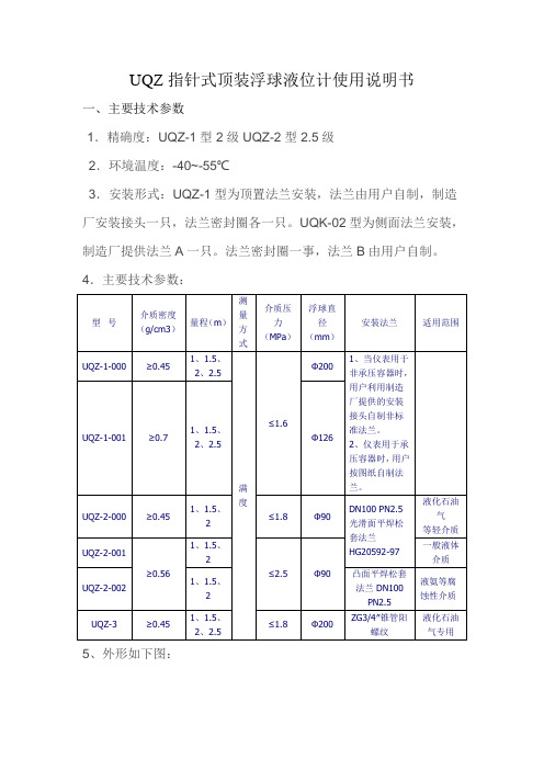
UQZ指针式顶装浮球液位计使用说明书一、主要技术参数1.精确度:UQZ-1型 2级 UQZ-2型 2.5级2.环境温度:-40~-55℃3.安装形式:UQZ-1型为顶置法兰安装,法兰由用户自制,制造厂安装接头一只,法兰密封圈各一只。
UQK-02型为侧面法兰安装,制造厂提供法兰A一只。
法兰密封圈一事,法兰B由用户自制。
4.主要技术参数:5、外形如下图:二、性能描述仪表出厂时,浮球用卡箍固定在密封管底部此时柱形磁钢在密封管顶部,与浮球脱离关系,用户在安装使用前应先拆去卡箍,将浮球缓缓推至密封管顶部,让浮球内磁球吸住密封管内的柱形磁钢,然后缓缓下移浮球,表头上指针跟着转动直至浮球到达密封管底部为止,以后在搬动仪表时注意不要让浮球在密封管上高速滑动或冲击,以免浮球和柱形磁钢脱开。
仪表用两根指针在表盘上指示液位值,长针指示厘米,其对就刻为每一小格一厘米,两者都是黑色的。
短针红色刻度线也是红色,指示米。
读数方式与时钟相仿。
仪表表头右下侧有一调零把手,通过转动表盘调零。
调零范围±5cm,松开前紧固螺钉轻轻拔动把手可以调零,调好后重新紧固螺钉。
仪表在使用时可在图板上的弧形环内涂颜色,以醒目的标注容器内不同充填区域,譬如V<10%涂黑色表示起始区:10%≤v≤80%涂绿色表示安全区,80%<>三、指针式顶装浮球液位计维护及注意事项1、仪表一般安装在量程的中点位置上。
2、UQZ-1、UQZ-2、UQZ-3系列浮球液位计应安装在其浮球上下运支时不受妨碍的位置上。
3、被测介质不应含用铁磁性杂质。
4、免浮球和柱形磁钢脱开。
5、的面扳指示为指针式,满度测量时指示数字为顺针方向排列,空度测量时指示数字为逆时针方向排列。
6、安装垂直度要符合要求,在介质存在流动时要避开急流安装,必要时可加强导杆固定或加装静止套。
7、为了防止运输时UQZ-1、UQZ-3型仪表的浮球的密封管上高速滑落或撞击,引起测量带脱出,故仪表在出厂前,用卡箍将浮球固定在密封管底部,磁钢在密封管顶部。
浮球液位计安装和使用说明注意事项范本
工作行为规范系列浮球液位计安装和使用说明注意事项(标准、完整、实用、可修改)编号:FS-QG-88984浮球液位计安装和使用说明注意事项Float level gauge installation and use instructions说明:为规范化、制度化和统一化作业行为,使人员管理工作有章可循,提高工作效率和责任感、归属感,特此编写。
浮球液位计的组成浮球液位计由浮球、插杆等组成。
浮球液位计通过连接法兰按装于容器顶上,浮球根据排开液体体积相等等原理浮于液面,当容器的液位变化时浮球也随着上下移动,由于磁性作用,浮球液位计的干簧受磁性吸合,把液面位置变化成电信号,通过显示仪表用数字显示液体的实际位置,浮球液位计从而达到液面的远距离检测和控制。
浮球液位计的注意事项浮球液位计应安装在其浮球上下运动时不受妨碍的位置上。
1.被测介质不应含有铁磁性杂质。
2.为了防止运输基本型MYFQ-JB磁性浮子液位计仪表的浮球在密封管上高速滑落或撞击,引起测量带脱出,故仪表在出厂前,用卡箍将浮球固定在密封密管底部,磁钢在密封管顶部。
用户在安装.3.使用前应先拆去卡箍,将浮球上升至密封管顶部,然后轻缓地将浮球下移,针针应作相应的转动。
4.浮球液位计的面扳指示为指针式,满度测量时指示数字为喱针方向排列,空度测量时指示数字为逆时针方向排列。
5.浮球液位计出厂时附有安装法兰,用户应有配管道法兰浮球液位计的2种浮动形式浮球液位计有两种浮动形式,一种是浮球动,导杆不动;另一种则是浮球和导杆同时动。
前一种浮球和导杆间不能有杂物,这一点选型时就要注意。
后一种要避免导杆溅上杂物,同时这种形式抗介质流动的能力较小,安装定位时要注意避免。
共同的基本要求是浮球上下运动时不能有阻碍。
安装垂直度要符合要求,在介质存在流动时要避开急流安装,必要时可加强导杆固定或加装静止套。
请输入您公司的名字Foonshion Design Co., Ltd。
浮球液位计UQDZ中文使用说明书(2012版A4)
UQD.Z型智能浮球液位变送器辽制00000252号1 前言非常感谢您选择丹东通博电器(集团)有限公司的产品。
本产品已通过国家级防爆认证,认证标志:本安型ExiaⅡCT1~T6;隔爆型ExdⅡCT1~T6。
使用前请仔细阅读使用说明书,特别是与防爆相关的环境温度等各项要求。
2 概述a) 本产品执行标准代号:Q/AMM 001-2010浮球液位变送器;b) UQD.Z型智能浮球液位变送器是模拟、数字与微处理器相结合的产品。
该变送器将模拟电压信号转换成4~20mA两线制电流输出信号,并且加载了HART协议通讯。
由于采用了HART总线技术,具有高精度,低漂移,抗干扰能力强等特点,可以实现对仪表的远程组态、监测、维护、及校准等功能,并可构成生产过程测量、监督管理系统。
c) 可广泛适用于粘稠、脏污、易燃易爆及腐蚀性介质以及其它介质液位的测量及液位信号的变送,是石油、化工、冶金、电力及轻工等工业部门生产过程控制中用于液位测量的理想仪表。
d) 型号的组成及其代表意义:3 结构特征与工作原理a)总体结构及工作原理、工作特性:UQD.Z智能浮球液位变送器主要由测量传感机构和智能变送器两大部分组成。
测量传感元件为圆球型浮球。
而变送器则采用平衡杆和平衡锤与浮球构成的力矩平衡机构,因此浮球可以自由地随液位的变化而升降。
根据不同的结构特点分为UQD.Z-90小转角型、UQD.Z-91大转角型、UQD.Z-92外浮球型三种结构,三种规格的电器性能和防爆级别均相同。
变送器具有现代流行壳体设计,造型美观且各工作腔室隔离等特点。
b)主要部件作用及其工作原理:当液位改变时,浮球的位置发生相应的变化,带动主轴转动,主轴与表头(发讯器)角位移传感器输出轴相连接,角位移传感器将浮球随液位的变化转换成相应的电信号,再由浮球控制器内部的电路将此信号转换为与液面变化成正比的标准电流信号。
c)单元结构的联系及工作原理:图 14 主要规格及技术参数4.1 主要参数·电源电压:24V DC;·输出:4~20mA叠加HART通信;·负载电阻:230~1100Ω;·阻尼时间选择:0~32秒;·测量范围:400~1200mm (小转角型);550~1600mm (大转角型) ;·公称压力:≤6.3MPa;·公称通径:DN250·精度等级:1.0级;1.5级·介质密度:≥0.55/cm3;·环境温度:-30℃~70℃;·工作温度:-30℃≤T≤225℃(无散热片);225℃<T≤450℃(带散热片);·法兰标准:HG/T20592-2009、HG/T20615-2009或按用户要求;·电源引入口:M20X1.5(内)或按用户要求;·防护等级:IP67;·诊断功能:仪表故障时,输出报警电流;·组态功能:工程单位、量程、显示、测量类型、介质密度、浮筒高度、报警等组态;·报警功能:可以设置报警上下限。
西安兴仪浮球液位计说明书
UQK-61系列悬挂式浮球液位控制器UQK-61Series Suspended Type Float ball Liquid Level Controller产品说明书Product seriesUQK-61系列悬挂式浮球液位控制器UQK-61Series Suspended Type Float ball Liquid Level Controller概要UQK-61系列悬挂式浮球液位控制器是利用浮球内藏接点来发信号的液位控制器。
球内密封一滑动磁环及一干簧转换接点,其引线为三芯橡套软电缆。
当液体到达给定位置时,浮球迅速翻转,磁环使接点动作。
浮球的固定位置及动作范围可按需要调节。
本控制器特别适用于含有固体、半固体状漂浮物的液体,粘度大的液体,不会产生被漂浮物卡死的故障。
可对生活污水池及生产废水池的水位进行测量,当然也可对清水池、水箱及水塔的水位进行测量。
一个浮球可测一个液位,也可测两个液位。
一个接线盒最多可接4个浮球。
本产品可与UQKX系列液位控制箱配套,对液位进行显示、控制及报警。
Brief IntroductionUQK-61Series Suspended Type Float ball Liquid Level Controller is the liquidlevel controller that sends signal by using the Touching point enclosed in the float ball, in which a sliding EMIFIL and a transferring Touching point of the main spring are sealed.The lead is a three-core soft cable with rubber coat.When the liquid reaches the given level,the float ball rolls over quickly,and the EMIFIL makes the Touching point work.The fixed level of float ball and the scope of the action can be adjusted according to the demands.This controller is especially applicable to the liquid containing solid and semi-solid float material or liquid of high viscosity;meanwhile,the controller can't be jammed by the float material.The product is applied to measure the water level in the sanitary sewage pools and production waste pools.It can also be used to measure the water level in the clean water pools,water tanks and water towers.One float ball can measure one or two liquid levels.One junction box can be connected up to4float balls.This product can be used together with in the UQKX Series liquid level controlling case to display,control and alarm the liquid level.型号Mode l主要技术性能Key Technical Performance1.控制范围1.Controlling Scope0.15〜10m2.控制精度2.Controlling Precision±0.02m3.工作条件3.Working Condition介质温度Medium TemperatureS球-10~+55°CBall S-10~+55°CG球-40~+150°CBall G-40~+150°C工作压力:‘’.Working Pressure:球常压Ball Normal Pressure球0.6MPaBall0.6MPa球材质F460.6MpaBall Material F460.6Mpa材质F40.25MPaMaterial F40.25MPa被测介质比重:0.65〜1.5Specific Gravity of Measured Medium:0.65~1.5触点输出:Output of Touching Point:触点形式常开、常闭、或转换型Type of Touching Point:Normally Open,Normally Closed or Switch Type触点容量220V.DC,1A220V.AC.1A(阻性)Capacity of Touching Point220V.DC’1A220V.AC.1A(Electric Resistance)主要部件材质:Materials of Main Components浮球S型ABS塑料Mode S ABS PlasticsG型不锈钢(lCrl8Ni9Ti)Mode G Stainless Steel1Crl8Ni9TiF型聚全氟乙丙烯(F46)或F4Mode F Perfluoro propene(F46)or F4重锤碳钢或铸铁,外涂保护漆(防腐型外涂4mm厚的F46材料)Movement Weight made of carbon steel or cast iron,with painted coating(anticorrosive F46material,thickness of4mm)coated outside)悬索尼龙绳(防腐型外套F4套管)Suspended Wire made of nylon rope(anticorrosive coating with F46sleeve)导线双芯软塑料护套线(出厂长度为6m,但可按用户要求加长)Lead double-corded soft plastic-sheathed flexible cord(with the producing length of6m,or longer than that in accordance with thedemands of customers)安装与接线安装图参见图5-1〜5-3有三种安装方法:1.让球体成垂直状态,电缆穿在硬塑料管或钢管中(底端需露出100〜150mm长的电缆),然后固定在指定的液位上(参见图5-2a)2.把球体直接抛入液体中,球体上端约100〜150mm处夹有一个控制液位的重锤,将球体顶端的电缆某处固定在指定的液位上,使浮球成自然垂直状态(参见图5-2b).3.把多个球体上的电缆分别穿在固定管或角钢的指定的位置上(端部需露出WO〜150mm长的电缆),然后将固定管或角钢固定好(参见图5-1)。
浮球液位计说明书

浮球液位计说明书篇一:JPF系列小型浮球液位开关说明书浮球液位开关说明书一、产品简介JPF系列浮球液位控制器是一种安全可靠、使用方便、结构简单的液位控制器,它比一般机械开关体积小、速度快、工作寿命长、与电子开关相比,它又有抗负载冲击能力强的特点,其在造船、造纸、印刷、发电机设备、石油化工、食品工业、水处理、电工、燃料工业、油压机械等方面都得到了广泛的应用。
二、工作原理在密封的不锈钢管(非导磁性)外穿过一个或多个环形磁铁的浮球,在安装一个或多个干簧管到管内,液位上下升降的同时会带动浮球一起移动,当浮球的磁铁到达管内干簧的同一水平位置时密封管内的干簧管产生吸合或断开的动作,并输出开关信号。
三、技术参数1. 触点容量:50W2. 开关电流:0.5A3. 开关电压:220V AC/24VDC4. 绝缘阻抗:>100MΩ5. 工作寿命:100万次6. 工作压力:1.0~3.0MP(常压1.0MPA)7. 工作温度:SUS:-10~200℃PP:-10~80℃(常温80-120℃)8. 介质比重:>0.55-1.09. 产品材质: SUS304/SUS316/PP/PE/PTFE四、小型浮球液位开关安装示意图注意事项:a、长度可由用户自定。
b、控制点可以做一点或二点。
c、控制点可以为N.O.或N.C.五、小型浮球液位开关接线图张家港市建胜测控仪表有限公司联系人:何建平电话0512-5537910913776266608篇二:UQZ-2指针浮球液位计说明书型浮球液位计产品说明书UQZ-2一、用途UQZ-2型浮球液位计是用于直接指示各种敞开或承压容器内液位高度的指示仪表。
仪表与工业设备上常用的玻璃管液面计相比较,它不怕破裂,示数更为清晰,尤其适宜于对玻璃管壁有粘滞作用的油污类液体介质或者有毒有害的介质的直接指示。
仪表具有不怕振动的优点,故可以安装在流动性的容器上,如槽车和液化气槽车。
该仪表不适用于对黄铜、铝、不锈钢等材质有较强腐蚀作用的介质。
LevelSite 磁性浮球液位计说明书

Level1LevelSite ® Supplemental GuideFeaturesModel LSSMin Typical SystemFigure 12from the liquid; the tank remains sealed from the surrounding environment (See Figure 2). Accidental spills from sight-glass breakage are eliminated.LevelSite® consists of 3 major components: the float housing, a magnetic float, and the rotating flagassembly. The float housing is an engineered pressure vessel which is externally mounted to the tank. The float housing is designed to handle the same temperatures andpressures found in the tank. It is fabricated from a variety of materials, depending on the application. The alloy models are usually polyvinyliden fluoride (PVDF). Other materials are available on request.The float (See Figure 3), is equipped witha permanent ring magnet assembly. Thisassembly rides at the surface of the liquidcontained within the float housing, rising and falling as the liquid in the tank rises and falls.As the float moves up and down, a magnetic flux field maintains continuous contact with the rotating flags mounted on theoutside of the float housing. Flag rotation occurs as the fluxFigure 3Standard Alloy Float has a resolution of 1/2” (12.7 mm). Rotating flags have a square profilewith embedded permanent magnets. The flux field generated by the ring magnet in the float interacts with the flag magnets causing them to rotate as the float moves up and down inside the housing. After the flags rotate to the new position, the embedded magnets lock the flags in place, making the flags less sensitive to vibration (See Figures 4 and 5).LevelSite®’s rotating flags are mounted in a housingfabricated of extruded aluminum or polycarbonate. The assembly is attached to the outside of the float housing with stainless steel clamps. The ends are sealed against dust and moisture. Since the flags are never in contact with the liquid, they never need to be cleaned and they can’t discolor. If the rotating flag assembly is accidentally crushed, there is no danger of a liquid spill.The rotating flag assembly is available in aluminum orpolycarbonate and measures 1.18”(30 mm) and 1.02” (26 mm) wide,respectively (See Figure 6).Figure 5Figure 6Level3LevelSite ® Supplemental GuideGeneral SpecificationsAluminum flags are offered in an anodized finish of red andsilver or painted in red and white. Anodized flags are suitable for service up to 400°F (200°C); painted versions can be subjected to 600°F (316°C). A glass pane protects the flags. The housing is extruded, black anodized aluminum.Polycarbonate flag housings are clear and impact-resistant. They offer 180° visibility of the flags; level can be seen from front and sides (See Figure 5). Housing and flags can withstand temperatures to 250°F (121°C). Standard flag colors are red and white.LevelSite®s are designed according to the unique requirements of each application. Based on information provided by the user regarding operating temperature, pressure, and “normal” specific gravity of the liquid, a float is selected appropriate to the application. Maximum and minimum conditions are evaluated to ensure that the LevelSite® will function not only at the normal condition, but at each extreme. Maximum temperature and pressure are parameters used to design the pressure vessel (float housing).9 can be used as a guide in selecting the ANSI class flanges and materialsappropriate for your temperature and pressure conditions.Barksdale’s LevelSite® is a unique system that can be custom designed for many types of applications, from a stand-alone, no-power-required levelindicator to a fully-integrated electroniccomponent within a process controlsystem. It can be supplied with process connections located for any of the four standard patterns: top/bottom, top/side, side/side, or side/bottom (See Figure 7). For applications where tank-side mounting of the LevelSite is not practical or desired, top mounted versions are available. Liquid interface configurations require three process connections (See Figure 7).Quality and dependability are built into every BarksdaleLevelSite. As a registered ISO 9001 manufacturer, Barksdale meets the most demanding international standards. LevelSite® can be certified to ASME, ANSI, DIN, BSP and other codes.System SpecificationsFigure 7ConfigurationQualityMaterialPressure/temperature performance parameters for LevelSite housing constructed of 316 stainless steel are specified in the chart. Please consult the factory with pressures/temperatures requiring other alloys.MaterialPressure/temperature performance parameters for LevelSite housing constructed of PVC, PP or PVDF are specified in the chart. Please consult the factory with pressures/temperatures requiring other materials.Figure 8Alloy - maximum operating pressure vs.temperature for ANSI classification.Figure 9Engineered plastic - maximum operating pressure vs. temperatureSee Barksdale’s Standard Conditions of Sale • Specifications are subject to modification at any time • Bulletin #L0018-D • 02/08 • ©2008 • Printed in the U.S.A.43211 Fruitland Avenue • Los Angeles, CA 90058 • 800-835-1060 • Fax: 323-589-3463 • LevelSite ® Supplemental GuideOperating InstructionsGeneral InstallationLevelSite®s are measuring instruments and must be properly treated as such. Make sure that all parts are available and the connecting flanges on the tank correspond to those on theindicator. The float and limit switches (if applicable) are enclosed in a separate box. Remove the bottom connection flange (1) of the float chamber and insert the float with the top uppermost. Replace the bottom flange with the gasket, fixing it to the chamber by tightening all the bolts securely. The LevelSite® must be raised slowly and carefully so that the float is not damaged by severe impact.It is essential to ensure that the flanges on the tank are accurately aligned with the flanges on the LevelSite®. Non-alignment of the flanges causes distortion of the float chamber (2) with the possibility that the float (3) will stick. The Levelsite® must always be mounted vertically. Before commissioning, the flags in the flag assembly (4) must be aligned by means of a magnet so that they all show the color white (polycarbonate) or silver (aluminum). NOTE: It is essential for all flange bolts, the vent-plug (5) and the drain-plug (6) to be fully tightened.The electrical limit switches (7) may be attached at any point in the range on the indicator bar by means of a stainless steel clip. Ensure that the stainless steel clips are installed under the flag assembly. The maximum electrical switching capacity is specified on the nameplate of the limit switch (7) and must not be exceeded. IMPORTANT: The operation of the LevelSite® is based on the magnetic field principle. Ferrous strips, clamps, or screws must not be used.LevelSite®s are always application specific. The most important technical data such as pressure and temperature limits are specified accurately on the nameplate (8). However, the sales drawing for the model number referenced on the nameplate is specific and detailed to the application and is the governingspecification document. Before commissioning, a check must be made to ensure that the technical data shown on the nameplate corresponds exactly with the plant requirements. NOTE: Test pressure and test temperature of the plant must NOT exceed the specifications.The transmitter is installed on the side of the LevelSite® housing, utilizing stainless steel clips, with the transmitter’s probe along the housing. The transmitter may be used in addition to a visual indicator (rotating flag assembly) to provide electronic monitoring of fluid level. If the transmitter is used with a flag assembly, it may be necessary to slide the transmitter’s clamps under the flag assembly. The transmitter is supplied with a mark on its probe. This mark must line-up with the centerline of the processMechanical InstallationElectrical InstallationCommissioningconnector on the LevelSite®. If the transmitter’s probe spans the entire measuring range (center-to-center of the process connections), the probe will be marked to show the measuring range. Electrical Connections: Ground the transmitter’shousing if necessary. The cable length may be up to 3 miles. The transmitter is designed to be maintenance-free and is not field-serviceable. If the unit is not operating properly, replace the entire unit. For more information, refer back to “Tank Level Indicating Transmitter”.Tank Level Indicator (TLI) Installation。
UQK浮球液位计使用说明书
UQK浮球液位计使用说明书
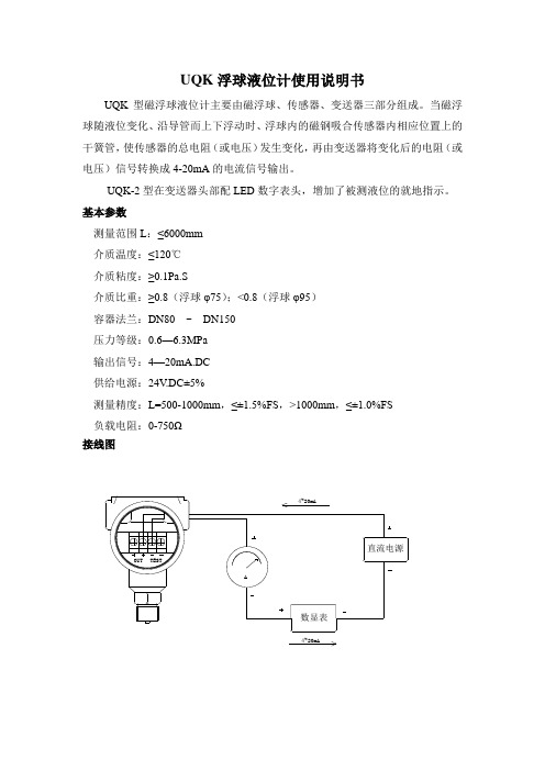
UQK型磁浮球液位计主要由磁浮球、传感器、变送器三部分组成。
当磁浮球随液位变化、沿导管而上下浮动时、浮球内的磁钢吸合传感器内相应位置上的干簧管,使传感器的总电阻(或电压)发生变化,再由变送器将变化后的电阻(或电压)信号转换成4-20mA的电流信号输出。
UQK-2型在变送器头部配LED数字表头,增加了被测液位的就地指示。
基本参数
测量范围L:≤6000mm
介质温度:≤120℃
介质粘度:≥0.1Pa.S
介质比重:≥0.8(浮球φ75);<0.8(浮球φ95)
容器法兰:DN80 ~ DN150
压力等级:0.6—6.3MPa
输出信号:4—20mA.DC
供给电源:24V.DC±5%
测量精度:L=500-1000mm,≤±1.5%FS,>1000mm,≤±1.0%FS
负载电阻:0-750Ω
接线图
4~20mA
直流电源
OUT TEST
A
数显表
4~20mA
UQK-1是安装在容器上部,打开接线盒盖,接入引出线,注意正负板不能接错,盖上盒盖并按紧螺钉使引出线固定,按线参照UDZ-3及其注意事项。
UQK-2是带LED表头的,打开显示盖,拨出LED表头,中间二个接线端子“+”、“-”,接入引出线,注意正负数不要接错,插上LED表头,盖上显示盖。
LED显示液位高度。
常州华音电子有限公司。
微光传感器 浮球连续式液位指示计 使用说明书

3、选择安装管径大于浮球直径的法兰连接管,见图7。
变送器调整1、液位计在出厂前已经根据用户的订货要求调整好,用户不可以随意调整。
2、若变送器输出显示值与液面不一致时,用户可以对液位变送器作进一步的调整,具体调整方法如下:a)将浮球置于零位处,调节“ZERO”使输出电流为4mA。
b)将浮球置于满位处,调节“SPAN”使输出电流为20mA。
注意:液位计在使用过程中,不得随意打开接线盒调节“ZERO”和“SPAN”电位器,以免造成液位计信号输出错误。
开箱及检查1、液位计包装应该完好无损。
2、开箱时若发现液位计有损坏或附件脱落松动等异常情况,请及时通知本公司。
3、装箱内容:a)液位计1台;b)液位计使用说明书1份;c)产品合格证浮球连续式液位指示计使用说明书地址:陕西省宝鸡市英达路18号电话:************传真:************邮编:721006网址:制订日期:2019年01月23日 V2.0版图6d图7d>浮球直径时才能安装基本参数1、解析度:6.35mm、12.7mm2、测量范围:0m~6m3、输出信号:二线制(4~20)mA DC;三线制电阻输出(0~1)MΩ。
4、供电电压:二线制(13~36)V DC;三线制5V DC。
5、工作温度:-10℃~80℃(PP);-20℃~120℃(PVDF 、SUS)6、变送器工作温度:-20℃~80℃7、工作压力:3.0MPa(MAX)工作原理该液位计是利用浮球内磁铁随液位变化,来改变连杆内的电阻与磁簧开关所组成的分压电路,磁簧开关的间隙愈小,精度愈高。
分压信号可经过信号变送器转换成4mA~20mA DC或其它不同的标准信号,指示器可配合其它表头作远距离指示。
变送器配线图1、二线制液位计为三线制液位计外加一变送器,将电阻信号转换成4mA~20mA DC电流信号输出,接线为:电源﹢24V DC接液位计﹢24V端子,电源负极接液位计O/P端子,将电流表串到电源与液位计中,实现4mA~20mA DC测量;配合光棒电表接线图,见图1。
- 1、下载文档前请自行甄别文档内容的完整性,平台不提供额外的编辑、内容补充、找答案等附加服务。
- 2、"仅部分预览"的文档,不可在线预览部分如存在完整性等问题,可反馈申请退款(可完整预览的文档不适用该条件!)。
- 3、如文档侵犯您的权益,请联系客服反馈,我们会尽快为您处理(人工客服工作时间:9:00-18:30)。
浮球液位计说明书
篇一:
浮球液位计
说明书
USX型磁浮球液位计
一、概述
浮球液位计由浮球、插杆等组成。
浮球液位计通过连接法兰安装于容器顶上,浮球根据排开液体体积相等等原理浮于液面,当容器的液位变化时浮球也随着上下移动,由于磁性作用,浮球液位计的干簧受磁性吸合,把液面位置变化成电信号,通过显示仪表用数字显示液体的实际位置,浮球液位计从而达到液面的远距离检测和控制。
浮球液位计具有结构简单,调试方便,可靠性好,精度高等特点,浮球液位计可广泛适用于高温、高压、粘稠、脏污介质、沥青、含腊等油品以及易燃、易爆、腐蚀性等介质的液位(界位)的连续测量。
浮球液位计可用于石油、化工原料储存、工业流程、生化、医药、食品饮料、罐区管理和加油站地下库存等各种液罐的液位工业计量和控制。
浮球液位计也适用于大坝水位,水库水位监测与污水处理等等
二、产品技术参数:
测量范围:0~3500mm 供电电压:12~36V DC
输出信号:两线制4~20mA.DC或叠加数字信号,由用户
选择开方或线性输出;负载电阻:250Ω
测量精度:±2.5%F.S 环境温度:-40~80℃工作温度:-20~120℃公称压力:≤2.5MPa
法兰标准:A:JB/T82.1-94(平面法兰)DN100 PN1.6 球φ90 B:JB/T82.1-94(平面法兰)DN80 PN0.6 球φ76
33
介质密度:≥0.65g/cm 介质粘度:≤0.015Pa.s 接液材质:不锈钢304 防爆等级:EX iaⅡCT 5
三、接线图
四、选型
型号示例:
插入深度2200mm,测量范围0-20XXmm,地下型(内置传感器上装式),配现场数显仪表(一次表),配套XM型智能数显仪可提供对外控制(触点常开动闭),普通型产品。
标记为:USX2-2200/20XXPAKb
五、浮球液位计校验与试验:
a. 下限(即零点)调试:浮球处于最低位置时(即零点),调下限旋钮,使数显表显示4mA。
b.上限(即满度)调试:将浮球移至最高位置或设定位置时(即满度),调上限旋钮,使数显表显示输出20mA。
六、维护与检修质量标准:
浮球液位计在投入运行前应做以下工作。
a.浮球液位计工作时,通常应在正常范围内工作。
b.经常检查浮球液位计的附件设备、电源、输出信号是否正常; d.浮球液位计运行是否平稳,输出信号与液位是否对应;
e.工艺连接法兰是否严密不漏,密封腔的密封和转动轴承连接处有无介质外漏;检查中发现的问题要及时处理,以保证浮球液位计正常运行;
f.需对浮球液位计进行解体检查时,必须先将工艺容器降温、降压、隔离、置换,待工艺容器降温,降压、隔离、置换合格后,符合安全规定后方可进行。
七、检修质量标准:
a.零部件齐全,装配关系正确,紧固件不得有松动现象,整体洁净;
b.电源电压范围符合铭牌上的标准,标准电流信号范围为DC4—20mA;
c.符合耐压强度要求浮球液位计应以规定的压力进行与压力容器同步进行耐压强度试验,不应有渗漏;
d. 保证浮球液位计误差符合设计测量精度;
八、试验与验收:试验
检修后的浮球液位计必须与压力容器同步进行气密性试验,介质压力应符合工艺气密压力要求,否则
应检查漏点予以彻底消除。
密封性及强度试验介质是氮气。
密封性试验压力为公称压力,强度试验压力。
验收
经过检修的浮球液位计符合下列条件方可验收。
a.有浮球液位计仪表校验记录并存档;
b.大修后按车间检修记录表内容填写,档案资料齐全准确;
c.按检修内容的各项目逐条检查完成情况并检查合格;
九、常见故障及处理方法:
数显表接线图示
C80系列横式
带数字表头的需要先拔出表头,数显表端子(13)接到24V+;数显表端子(7)接到24V- 接线完毕插上数字表头通电即可
篇二:UQZ-2指针
型浮球液位计
产
品
说
明
书
UQZ-2
一、用途
UQZ-2型浮球液位计是用于直接指示各种敞开或承压容器内液位高度的指示仪表。
仪表与工业设备上常用的玻璃管液面计相比较,它不怕破裂,示数更为清晰,尤其适宜于对玻璃管壁有粘滞作用的油污类液体介质或者有毒有害的介质的直接指示。
仪表具有不怕振动的优点,故可以安装在流动性的容器上,如槽车和液化气槽车。
该仪表不适用于对黄铜、铝、不锈钢等材质有较强腐蚀作用的介质。
二、结构和原理
液位计结构原理见图一。
当容器内被液位升降时,浮球1随之升降,通过连杆2带动一对简化齿轮3动作,从而使与齿轮同轴的一块π型磁钢4产生转动。
通过磁力的作用带动位于表头内的另一块π型磁钢5作相应的转动,与5同轴的指针6便便在度板7上指示一定的液位值。
图一 UQZ-2型结构原理图
1.浮筒
2.连杆
3.简化齿轮
4.5.π型磁钢 6.指针
7.度板
三、主要技术数据
精度等级:2.5级被测介质温度:<120℃(特制<350℃)
环境温度:-40~+50℃安装形式:侧置式法兰连接。
仪表的各项指标均符合一九八一年二月原国家劳动总
局颁发的《液化石油气汽车槽车安全管理规定》中液面计的有关要求。
1型号、
规格及适用范围
四、安装、使用及维护
1、用户应自配管道法兰B(JB83-59,平焊法兰),亦可直接用具有相应密封面的凸缘代替图三中的接管式连接。
具体步骤:
①从人工孔进入罐内焊接导轨(不用导轨时省略)
②将仪表管和罐孔焊接,或法兰连接
③罐内浮球导杆过导轨安装浮球(不用导轨时省略)
④调试浮球位置和表盘指针指示量程相同即可。
(无人工孔时,在罐外调试好安装)
2、槽车在使用时,可在图板上方的弧形环内分段涂上规定的颜色标记,醒目地表示容器内不同的充装区域。
如V >10%内涂黑色,表示起始区,10%≤V≤80%内涂绿色,表示安全区,80%≤V≤85%涂黄色,表示禁界区,85%≤V涂红色,表示危险区。
3、液位计安装位置一般应选择在量程之半,还应保证在连杆摆角范围内没有妨碍摆动机构运动的支架或构件。
4、被测介质不应含有铁磁性杂质。
五、订货须知
产品型号、名称、量程
被测介质工作压力
容器种类
非标产品参考相近型号价格
附:非标特殊型号规格及适用范围
六、本产品标准代号:Q/TFZ02-20XX
---------------------------------------------------
---------------------------
篇三:UQK浮球液位计使用说明书
UQK浮球液位计使用说明书
UQK型磁浮球液位计主要由磁浮球、传感器、变送器三部分组成。
当磁浮球随液位变化、沿导管而上下浮动时、浮球内的磁钢吸合传感器内相应位置上的干簧管,使传感器的总电阻(或电压)发生变化,再由变送器将变化后的电阻(或电压)信号转换成4-20mA的电流信号输出。
UQK-2型在变送器头部配LED数字表头,增加了被测液位的就地指示。
基本参数
测量范围L:≤6000mm
介质温度:≤120℃
介质粘度:≥0.1Pa.S
介质比重:≥0.8(浮球φ75);容器法兰:DN80 ~
DN150
压力等级:0.6—6.3MPa
输出信号:4—20mA.DC
供给电源:24V.DC±5%
测量精度:L=500-1000mm,≤±1.5%FS,>1000mm,≤±1.0%FS 负载电阻:0-750Ω
接线图
4~20mA
直流电源
OUTTEST
A
数显表
4~20mA
UQK-1是安装在容器上部,打开接线盒盖,接入引出线,注意正负板不能接错,盖上盒盖并按紧螺钉使引出线固定,按线参照UDZ-3及其注意事项。
UQK-2是带LED表头的,打开显示盖,拨出LED表头,中间二个接线端子“+”、“-”,接入引出线,注意正负数不要接错,插上LED表头,盖上显示盖。
LED显示液位高度。
常州华音电子有限公司。