Fluke应用软件中文说明
Fluke 718Ex_用户手册中文版(校准器)

718Ex 30G/100G/300G Pressure Calibrator
May 2004 Rev. 2, 5/09 (Simplified Chinese)
© 2004-2009 Fluke Corporation. All rights reserved. Specifications are subject to change without notice. All product names are trademarks of their respective companies.
Fluke Corporation
Fluke Europe B.V.
P.O. Box 9090
P.O. Box 1186
Everett, WA 98206-9090
5602 BD Eindhoven
U.S.A.
The Netherlands
要上网注册您的产品,请访问 。
Fluke 仅授权经销商将本保证提供给购买新的、未曾使用过的产品的最终用户。经销商无权以 Fluke 的名义来给予其它任何担保。保修服务仅 限于从 Fluke 授权销售处所购买的产品,或购买者已付出适当的 Fluke 国际价格。在某一国家购买而需要在另一国家维修的产品,Fluke 保留 向购买者征收维修/更换零件进口费用的权利。 Fluke 的保证是有限的,在保修期间退回 Fluke 授权服务中心的损坏产品,Fluke 有权决定采用退款、免费修理或更换产品的方式处理。 欲取得保证服务,请和您附近的 Fluke 服务中心联系,或把产品寄到最靠近您的 Fluke 服务中心(请说明故障所在,预付运费和保险费用,并 以 FOB 目的地方式寄送)。Fluke 不负责产品在运输中的损坏。保修期修理以后,Fluke 会将产品寄回给购买者(预付运费,并以 FOB 目的 地方式寄送)。若 Fluke 判断故障是由于疏忽、误用、污染、修改、意外或非正常的工作条件或处理方式(包括使用产品指标以外的过电压故 障或机械部件的一般磨损)而产生,Fluke 会对维修费用作出估价,并取得购买者的同意以后才进行维修。维修后,Fluke 将把产品寄回给购 买者(预付运费,FOB 运输点),同时向购买者征收维修和运输的费用。 本项保证是购买者唯一及专有的补偿,并且它代替了所有其它明示或默示的保证,包括但不限于保证某一特殊目的适应性的默示保证。凡因任 何原因所引起的特别、间接、附带或继起的损坏或损失(包括数据的损失),FLUKE 也一概不予负责。 由于某些国家或洲不允许对默示保证及附带或继起的损坏有所限制,本保证的限制及范围或许不会与每位购买者有关。若本保证的任何条款被 具有合法管辖权的法庭裁定为不适用或不可强制执行,该项裁定将不会影响其它条款的有效性或强制性。
fluke使用说明书
fluke使用说明书福禄克flukedtx系列(dtx-1800,dtx-1200,dtx-lt)简单操作步骤说明:一、福禄克测试仪初始化步骤:1、充电:产品主机、辅机分别用电源适配器充电,直至电池显示灯转为绿色;2、设置语言:操作方式:将flukedtx系列产品主机旋钮转回至“setup”档位,按右下角绿色按钮开机;采用↓箭头;选上第三条“instrumentsetting”(本机设置)按“enter”步入参数设置,首先采用→箭头,按一下;步入第二个页面,↓箭头挑选最后一项language按“enter”步入;↓箭头挑选最后一项chinese按“enter”挑选。
将语言选择成中文后才展开以下操作方式。
3、自校准:取flukedtx系列产品cat6a/classea永久链路适配器,装在主机上,辅机装上cat6a/classea通道适配器。
然后将永久链路适配器末端插在cat6a/classea通道适配器上;打开辅机电源,辅机自检后,“pass”灯亮后熄灭,显示辅机正常。
“specialfunctions”档位,关上主机电源,表明主机、辅机软件、硬件和测试标准的版本(辅机信息只有当辅机开机并和主机相连接时才表明),自测后表明操作界面,挑选第一项“设置基准”后(例如看错用“exit”选择退出重复),按“enter”键和“test”键已经开始自校准,表明“设置基准已完成”表明自校准顺利顺利完成。
二、设置福禄克测试仪基本参数操作:将flukedtx系列产品主机旋钮转至“setup”档位,使用“↑↓”来选择第三条“仪器值设置”,按“enter”进入参数设置,可以按“←→”翻页,用“↑↓”选择你所需设置的参数,按enter进入参数修改,用“↑↓”选择你所需采用的参数设置,选好后按enter选定并完成参数设置。
1、新机第一次采用须要设置的参数,以后不须要修改。
(将旋钮转回至“setup”档位,采用↓箭头;选上第三条:仪器设置值按enter步入如果回到上一级恳请按exit):1)线缆标识码来源:(一般使用自动递增,会使电缆标识的最后一个字符在每一次保存测试时递增一般不用更改)2)图形数据存储:(就是)(否)通常情况下挑选(就是)3)当前文件夹:default可以按enter进入修改其名称(你想要的名字)4)结果存放位置:(使用默认值“内部存储器”假如有内存卡的话也可以选择“内存卡”)5)按→进入第2个设置页面,操作员:youname按enter进入按f3删除原来的字符“←→↑↓”来选择你要的字符选好后按enter确定11)长度单位:通常情况下挑选米(m)2、新机不须要设置使用原机器默认值的参数:1)电源停用超时:预设30分钟2)背光超时:预设1分钟3)可以听音:预设就是4)电源线频率:默认50hz5)数字格式:预设就是00.06)将旋钮转至“setup”档位选择双绞线按enter进入后nvp不用修改7)光纤里面的设置,在测试双绞线是不须修改3、采用过程中经常须要改动的参数:将旋钮转至“setup”档位,选择双绞线,按enter进入:线缆类型:按enter进入后按↑↓选择你要测试的线缆类型例如我要测试超5类的双绞线在按enter进入后选择utp按enter↑↓选择“cat5eutp”按enter返回。
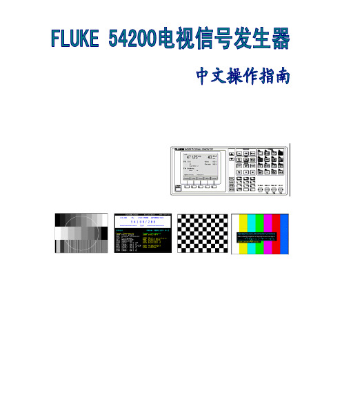
FLUKE54200中文操作指南
FLUKE54200中文操作指南仪器的设定和检查 开机之后, 仪器自动地被设定为上一次关机之前的设置。
例如:图3-1. 主菜单按standard 软键(F1) 出现选定国家的省缺设置子菜单,例如,英国图3-2. 该国家的视频标准和伴音制式按edit 软键(F3) 弹出预先定义的国家目录列表菜单 按↑或者↓软键(F1或者F2)选择国家,例如,德国。
如果你需要的国家没有被列出, 就选择一个和你要使用的国家相同或相似的视频标准和伴音制式。
图3-3. 预先定义的国家目录列表菜单按enter 软键(F5)确认你的选择 屏幕显示出你所选择国家的视频标准和伴音制式图3-4. 所选国家的视频标准和伴音制式 如果你的电视机不支持该制式,可以通过按↑或者↓软键(F1或者F2)来选择你所需要的视频标准和伴音制式,例如,FM Germany按edit 软键(F3)按↑或者↓软键(F1或者F2)来选择你所需要的标准和伴音制式,例如,FM Mono按enter 软键(F5)确认你的选择再按enter 软键(F5)回到主菜单图3-5. 设定后的主菜单检查video(视频) 和 chroma(色度) 的幅度是否设置为 100%如果不是,按video 软键(F2),屏幕显示出video(视频)子菜单当前所有的设置。
图3-6. video(视频)子菜单当前的设置按edit 软键(F3)弹出一个可以输入数字的菜单图3-7. video(视频)幅度设置 使用数字按键输入100 按enter 软键(F5)确认你的输入 按↑软键(F2)来选择chroma(色度)使用数字按键输入100 按enter 软键(F5)确认你的输入 再按enter 软键(F5)回到主菜单图3-8. 改变设置后的主菜单按显示屏右边的FREQ 键,选择适当的射频载波频率,例如,203.25 MHz 弹出一个数字输入菜单图3-9. 载波频率设置使用数字按键输入203.25按enter 软键(F5)确认你的输入图3-10. 选定载波频率将你的电视机设置为相同的频率或相应的电视频道,在这个例子里,是9频道。
fluke中文使用手册805

May 2012 (Simplified Chinese)© 2012 Fluke Corporation. All rights reserved. Specifications are subject to change without notice. All product names are trademarks of their respective companies.805 Vibration Meter用户手册有限担保及责任范围Fluke 公司保证其每一个Fluke的产品在正常使用及维护情形下,其用料和做工都是毫无瑕疵的。
保证期限是一年并从产品寄运日起开始计算。
零件、产品修理及服务的保证期是 90天。
本保证只提供给从 Fluke授权经销商处购买的原购买者或最终用户,且不包括保险丝、电池以及因误用、改变、疏忽、或非正常情况下的使用或搬运而损坏(根据 Fluke的意见而定)的产品。
Fluke 保证在 90天之内,软件会根据其功能指标运行,同时软件已经正确地被记录在没有损坏的媒介上。
Fluke 不能保证其软件没有错误或者在运行时不会中断。
Fluke 仅授权经销商将本保证提供给购买新的、未曾使用过的产品的最终用户。
经销商无权以 Fluke的名义来给予其它任何担保。
保修服务仅限于从 Fluke授权销售处所购买的产品,或购买者已付出适当的Fluke国际价格。
在某一国家购买而需要在另一国家维修的产品,Fluke 保留向购买者征收维修/更换零件进口费用的权利。
Fluke 的保证是有限的,在保用期间退回 Fluke授权服务中心的损坏产品,Fluke有权决定采用退款、免费维修或把产品更换的方式处理。
欲取得保证服务,请和您附近的Fluke服务中心联系,或把产品寄到最靠近您的Fluke服务中心(请说明故障所在,预付邮资和保险费用,并以 FOB目的地方式寄送)。
Fluke 不负责产品在运输上的损坏。
Fluke 19xC-2x5C ScopeMeter 用户操作指南说明书

Fluke 19xC-2x5CScopeMeterSoftware version 8.00 onwardsGetting StartedGBJun 2008, Rev. 1, 09/2009© 2008, 2009 Fluke Corporation, All rights reserved. Printed in the NetherlandsAll product names are trademarks of their respective companies.Table of ContentsPage TitleUnpacking the Test Tool Kit (ii)Introduction (1)Contacting Fluke (1)Safety Information: Read First (1)Preparing for Use (4)Powering/Resetting the Test Tool (4)How to Navigate a Menu (example) (4)Changing the Information Language (5)Adjusting Contrast and Brightness (5)Using the Scope (5)Multimeter (7)Recorder Functions (8)Fieldbus Measurements (Bushealth) (8)Replay (10)Zoom (10)Making Cursor Measurements (11)Triggering (11)Saving/Printing Screens and Setups (13)User Options (20)iFluke 19xC-2x5CGetting StartediiUnpacking the Test Tool KitThe following items are included in your test tool kit: 1. ScopeMeter Test Tool 2. Battery Charger3. 10:1 Voltage Probe Set (Red)4. 10:1 Voltage Probe Set (Gray)5. Test Lead Set (Red and Black)6. Bus Health Test adapter (2x5Conly)7. Safety Information + CD ROMwith complete Users Manual 8. Shipment box (basic versiononly) The -S versions also include: 9. Optically Isolated USBAdapter/Cable10. CD ROM with FlukeView ®Software 11. Hard CaseGetting StartedIntroductionThis Getting Started Manual provides basic information on Models 192C, 196C, 199C, 215C and 225C, software versions V08.00 and newer. Refer to the Users Manual on the accompanying CD-ROM for complete operating instructions.Contacting FlukeTo locate an authorized service center, visit us on the World Wide Web at: or call Fluke using any of the phone numbers listed below:+1-888-993-5853 in the U.S.A and Canada+31-40-2675200 in Europe+1-425-446-5500 from other countries. Safety Information: Read FirstThe Fluke Models 192C, 196C, 199C, 215C and 225C ScopeMeter test tools (hereafter referred to as “test tool”) comply with:• ANSI/ISAS82.01-1994•EN/IEC61010-1 : 2001• CAN/CSA-C22.2No.61010-1-04•1000 V Measurement Category II, 600 VMeasurement Category III, Pollution Degree 2• UL61010B-1Use the test tool only as specified in the Users Manual. Otherwise, the protection provided by the test tool might be impaired.A Warning identifies conditions and actions that pose hazard(s) to the user. A Caution identifies conditions and actions that may damage the test tool.1Fluke 19xC-2x5C Getting Started2 To avoid electrical shock or fire:•Use only the Fluke power supply, ModelBC190 (Battery Charger / Power Adapter).•Before use check that the selected/indicatedvoltage range on the BC190 matches the localline power voltage and frequency.•For the BC190/808 universal BatteryCharger/Power Adapter use only line cordsthat comply with the local safety regulations.NoteTo accommodate connection to various linepower sockets, the BC190/808 universal BatteryCharger / Power Adapter is equipped with a maleplug that must be connected to a line cordappropriate for local use. Since the adapter isisolated, the line cord does not need to beequipped with a terminal for connection toprotective ground. Since line cords with aprotective grounding terminal are morecommonly available you might consider usingthese anyhow.To avoid electrical shock or fire if a test toolinput is connected to more than 42 V peak (30Vrms) or on circuits of more than 4800 VA:•Use only insulated voltage probes, test leadsand adapters supplied with the test tool, orindicated by Fluke as suitable for the Fluke19xC-2x5C ScopeMeter series.•Before use, inspect voltage probes, test leadsand accessories for mechanical damage andreplace when damaged.•Remove all probes, test leads andaccessories that are not in use.•Always connect the battery charger first tothe ac outlet before connecting it to the testtool.•Do not connect the ground spring (Figure 1,item f) to voltages higher than 42 V peak (30Vrms) from earth ground.•Do not apply input voltages above the ratingof the instrument. Use caution when using 1:1test leads because the probe tip voltage willbe directly transmitted to the test tool.•Do not use exposed metal BNC or bananaplug connectors.Getting StartedSafety Information: Read First3• Do not insert metal objects into connectors. • Always use the test tool only in the manner specified.Max. Input VoltagesInput A and B directly...............................300 V CAT III Input A and B via 10:1 probe...................1000 V CAT II 600 V CAT III METER/EXT TRIG inputs........................1000 V CAT II 600 V CAT IIIMax. Floating Voltage From any terminal to earth ground..........1000 V CAT II 600 V CAT III Between any terminal..............................1000 V CAT II600 V CAT IIIVoltage ratings are given as “working voltage”. They should be read as Vac-rms (50-60 Hz) for AC sinewave applications and as Vdc for DC applications. Measurement Category III refers to distribution level and fixed installation circuits inside a building.Measurement Category II refers to local level, which is applicable for appliances and portable equipment. The terms ‘Isolated’ or ‘Electrically floating’ are used in this manual to indicate a measurement in which the test tool input BNC or banana jack is connected to a voltage different from earth ground.The isolated input connectors have no exposed metal and are fully insulated to protect against electrical shock. The red and gray BNC jacks, and the red and black4-mm banana jacks can independently be connected to a voltage above earth ground for isolated (electrically floating) measurements and are rated up to 1000 Vrms CAT II and 600 Vrms CAT III above earth ground.If Safety Features are ImpairedUse of the test tool in a manner not specified may impair the protection provided by the equipment.Before use, inspect the test leads for mechanical damage and replace damaged test leads!Whenever it is likely that safety has been impaired, the test tool must be turned off and disconnected from the line power. The matter should then be referred to qualified personnel. Safety is likely to be impaired if, for example, the test tool fails to perform the intended measurements or shows visible damage.Fluke 19xC-2x5C Getting Started4Preparing for UseAt delivery, the installed NiMH batteries may be empty and must be charged for 4 hours (with the test tool turned off) to reach full charge:• use only the Fluke Battery Charger/Power Adaptermodel BC190• before use check that the BC190 voltage andfrequency range match the local line power range • connect the battery charger to the ac outlet• connect the battery charger to the appropriate input onthe test tool near Input B. CautionTo prevent decrease of the battery capacity, you must charge the batteries at least once a year.Powering/Resetting the Test ToolTurning power on/off:The test tool powers up in its last setup configuration.Resetting the test tool to the factory settings:+Turn power off, then press and hold the USER key and turn on. You should hear a double beep.How to Navigate a Menu (example)Display the input A function key labels.Show the Input A (input A) menu.The menu example shows that the input A signal isdisplayed non-inverted (Normal ) with full bandwidth (Full ). To let input A invert the input signal, and to limit the bandwidth to 20 MHz do the following:Hiding a menu or key label:Press the CLEAR MENU key.Getting StartedChanging the Information Language5Changing the Information LanguageDuring operation of the test tool messages may appear on the screen (for instance if you select a recorder function). You can select the language in which messages will be displayed.Display the USER key labels.Open the LANGUAGE menu to select a language.Adjusting Contrast and BrightnessUsing the ScopeConnect the probe(s) as shown in figure 2.Figure 2. Scope ConnectionsAUTO- MANUAL rangingAfter an Auto Set the trace position, range, time base and triggering will be automatically adjusted to assure a stable display of virtually any waveform.Perform an Auto Set or select Manualranging (toggle). AUTO or MANUAL appears at the top right of the screen.Use the light-gray RANGE , TIME and MOVE keys to change the view of the waveform manually.Fluke 19xC-2x5C Getting Started6Scope Readings and WaveformsAutomatic scope measurement results are shown asReading 1 (READING 1) and Reading 2 (READING 2) at the upper left and right display edge.Scope readings on (ON ) or off (OFF ).on A : Reading 1 (2) is input A result. on B : Reading 1 (2) is input B result. V ac ...dB : measurement function.Glitch Detect: glitch capture on or off. Average: waveform averaging on or off. Waveform:Normal : normal waveform display. Persistence... : waveform persistence.□ Digital Persistence: persistence off,short, medium, long, infinite. □ Envelope: envelope on, off. □ Dot-join : dot join on or offMathematics... : A+B, A-B, AxB, A vs B (XY mode), Spectrum (frequency spectrum FFT).Reference... : compare waveforms, pass/fail testing.MultimeterInput A and Input B SettingsInput A (B) on or off. Input coupling AC or DC.Probe Type: voltage, current or temperatureprobe.Attenuation: probe attenuation. Probe Cal...: calibration of 10:1 /100:1probe.Polarity: input polarity normal or inverted;variable input sensitivity.Bandwidth: bandwidth full, 10 kHz, 20 MHz.MultimeterConnect the test leads (Figure 1, item 5) to the 4-mmsafety banana jack METER input.Relative measurements on or off.Getting StartedRecorder FunctionsFirst, choose a measurement in Scope or Meter mode.RECORDER ANALYZEShow the recorder functions. Select arecorder function (Scope Trendplot, Scope Record, or Meter Trendplot), then pressto display the recorder key labels:Start (RUN ) or stop (STOP ) recording.Show the recorder options.Reference: time reference is time of day (Time of Day ) or time from start (From Start ).In Scope Record:Display Glitches: glitch detection on, or 10 kHz filter on.Mode: Single Sweep : stores samples until memory is full, then stops.Mode: Continuous : stores samples continuously; deletes first samples if memory is full.Mode: on Ext. ... : start (Start ), stop (Stop ) or continue (Run ) recording if triggered via the meter input (Ext.). Run requires one trigger per division in VIEW ALL mode.In Trend Plot:Reading 1 (2)... (Scope) or Measurement... (Meter) show the measurement functionmenu.VIEW ALL : see all stored samples.NORMAL: see the most recent 9 divisions.EXIT : exit the recorder mode.Fieldbus Measurements (Bushealth)The Bushealth function is standard available in the Fluke 215C-225C.Selecting the Bus TypeFieldbus Measurements (Bushealth) Toggle between scope screen (OFF) andbushealth screen (ON).Bushealth ScreenThe following icons are used to indicate the bus measurement status:bus activity indicators:Q (filled) : voltage measured{ (open) : no voltage measuredÑÑ(blinking) : activity{{ (both open) : no activityBusy, the tester is measuring/processing data.No reading available.Result OK .Warning. Result on edge of limitsResult not OK.Setting up the LimitsTo set up the test limits of the current bus type, do thefollowing:Note: Changed limits are marked by a * (asterisk).Getting StartedReplayIn scope mode, the test tool automatically stores the 100most recent screens. Use REPLAY to review these screens.From Scope mode show the REPLAY keylabels.Step through the previous screen. Step through the next screens. Continuously play the stored screens.Exit the REPLAY mode.ZoomUse the zoom function to obtain a more detailed view of a waveform.Making Cursor MeasurementsMaking Cursor MeasurementsCursors allow you to make precise digital measurements on live, on recorded, and on saved waveforms.Display the CURSOR key labels.Select cursor measurement type:measure signal height at one point of time. measure signal height difference of two points of time, and measure the time or the trace RMS value between the cursors. measure signal height at the cursor positions and between cursor positions.measure rise time and fall time.Select the cursor to be moved. Use the blue arrow keys to move.Depending on cursor measurement type: Automatic or manual risetime measurement on a single channel.Reading 2 is time (T ), frequency (1/T ) , or RMS value.Cursor measurements on trace A , B or M if A and B are on; M if Mathematics ... is on, see ScopeReadings and Waveforms on page 6. OFF : Switch cursor measurements off.TriggeringTriggering tells the test tool when to begin displaying the waveform.Automatic triggering assures a stable display of virtually any signal:Perform an auto set. AUTO appears at the top right of the screen. Input A is the default trigger source.Now you can take over basic trigger controls such as source, level, slope and delay:Display the trigger key labelsA B : trigger on input A or B waveform Ext : trigger on the meter-input signal.Select the trigger slope.Getting Started□Single Shot : the test tool waits for atrigger. After receiving a trigger, thewaveform is displayed and theinstrument is set to HOLD.Press to arm for a new trigger.Noise reject Filter: the noise reject filterreduces jitter on the screen whentriggering on noisy waveforms.NCycle: Each N th trigger results in a traceupdate.Video on A... : enables triggering on videosignals (input A only).Pulse Width on A... : enables triggering onqualified pulses (input A only).Trigger Point, Trigger DelayThe trigger icon shows the trigger point. Initially youhave two divisions of pre-trigger view (negative delay).To change the trigger delay, do the following:Hold down to adjust the trigger delay.If you move the trigger icon to the left of the screen, itchanges to . The status at the bottom of the screenshows for example:The 500ms indicates the (positive) delay between thetrigger point and the waveform display.Saving/Printing Screens and SetupsSaving/Printing Screens and SetupsYou can save screens, recordings and setups to memory, and recall them again from memory. You can print actual or recalled screens.Display the SAVE PRINT key labels.SAVE: save a screen + setup (Screen +Setup), or a record/replay/trendplot + setup(Record + Setup, Replay+Setup,TrendPlot+Setup) in a memory location.The Edit Name menu allows you to changethe name for the saved item:- press to select the characterto be changed.- press the arrow keys to select a character.- press to set default name.- press to save.RECALL : open the Recall (recall) menu.RECALL FOR REFERENCE: recall a screenas a reference waveform.RECALL SETUP: recall a setup. Test tool isin run mode.RECALL: recall a screen + setup, or arecord + setup. Test tool is in hold mode.CANCEL: Close menuPRINT: Print the displayed screen. Refer tothe User Options below for printer setupinformation.VIEW DELETE : open the View/Delete menu.DELETE: clear the selected memory.RENAME… : rename a saved item.VIEW : view and/or print a saved item.CANCEL: Close menu.NoteWhen saving a screen the most recently acquired waveform will be stored. Persistence waveforms will not be stored.Getting StartedUser OptionsDisplay the USER key labels.Open the options menu.Auto Set Adjust...Select how auto set (AUTO key) behaves:auto set on signals >15 Hz (fast response) or >1 Hz (slower response).set input coupling to DC (Set to DC ) or don’t change the input coupling setting.set glitch detection on (Set to On ) or don’t change the glitch detection setting.Battery Save Options...When powered on the battery only, the test tool initially shuts itself down 30 minutes after you pressed a key (not in Trend Plot or Scope Record).You can set the automatic power shutdown time to 5 minutes and to 30 minutes, or you can disable the automatic power shutdown (Disabled ).Battery refreshStart a battery refresh about four times a year to keep the batteries in optimal condition. The batteries will be fully discharged and charged again.Date adjust...Set the date (Year: Month: Day: ) and the date format (DD/MM/YY is day- month-year, MM/DD/YY is month-day-year).Time Adjust...Set the time clock (Hours - Minutes - Seconds).Printer Setup...Select a printer type and select the baud rate.Factory defaultClears all memories and sets the test tool to factory defaults.Display Options...Set the display to color (Color ) or black and white (Black and White ).。
fluke中文使用手册12E

i
12E 用户手册
测试保险丝 ................................................................................................................ 9 更换电池和保险丝 ..................................................................................................... 10 保养和零件..................................................................................................................... 10 一般规格 ........................................................................................................................ 11 精确度规格..................................................................................................................... 12
用户手册
有限担保和有限责任
Fluke 公司保证本产品从购买之日起三年内,其材料和工艺均无任何缺陷。本项担保不包括保险丝、可弃置的电池或者因意 外、疏忽、误用或非正常情况下的使用或处理而损坏的产品。Fluke 也未曾授权予经销商将本保证期延长。保证期间如果需要 维修,请将测试仪表附上故障说明送到购买仪表的分销商处。
fluke中文使用手册15B-17B

页码
1 1 1 5 5 5 6 6 6 6 6 6 7 8 8 9 9 9
i
15B & 17B
用户手册
测量频率和占空比(仅限 17B) ................................................................................ 维护................................................................................................................................ 一般维护.................................................................................................................... 测试保险丝 ................................................................................................................ 更换电池和保险丝 ..................................................................................................... 维修和零件 ..................................................................................................................... 通用技术指标 ................................................................................................................. 准确度指标 ..................................................................................................................... 10 10 10 11 11 11 12 14
fluke中文使用手册805彩图

快速参考指南
测量提示
指示灯状态 符合 ISO 10816-1 的振动烈度
机器 in/s
90˚
0.01 0.02 0.03 0.04
数据传输
LCD 显示屏
红外测温 传感器
绿灯亮 绿灯灭 将传感器尖端放到测试表面 上,尽量靠近轴承。 施加压 力,直到绿灯熄灭。
绿灯灭 数据测量完成。
红灯亮 出错。用力或持续 时间不足,无测量 数据。
1.10 1.77
测振仪运用一种专属的算法:Crest Factor + (CF+)。 为了方便用户理解,CF+ 的 烈度等级在 1 到 16 之间取值。 CF+ 值越高,说明轴承受损程度越大。 每次测量获得的 CF+ 值显示在测振仪显示屏的轴承字段。 按 和 可在 CF+ 值和 以加速度为单位的高频振动级别之间切换。
使用前必读
导航
一般性操作: 面底部提供了关于
在菜单选项间移动光 标或编辑菜单选项 调用上一个菜单 打开下一个菜单或设 定选项 为测振仪保存新的选 项设置
测振仪配置
“设置”菜单
测量
快速测量 自动保存测量值
每个菜单都在界 其内容的导航提示。
单位
为防止红外测温仪导致人身伤害: ●● 有关实际温度,请参阅发射率信息。 反光物体会导致测得的温度比实际温度要低。 这些物体会 产生烧伤危险。 ●● 请勿在高温且无人照看的情形下使用产品。 为防止靠近转动设备而导致人身伤害: ●● 在转动设备周围要小心。 ●● 让绳索和带子隐藏起来。
- 1、下载文档前请自行甄别文档内容的完整性,平台不提供额外的编辑、内容补充、找答案等附加服务。
- 2、"仅部分预览"的文档,不可在线预览部分如存在完整性等问题,可反馈申请退款(可完整预览的文档不适用该条件!)。
- 3、如文档侵犯您的权益,请联系客服反馈,我们会尽快为您处理(人工客服工作时间:9:00-18:30)。
Fluke View和Fluke Power Log软件使用手册 1.软件的安装:
Fluke view软件的安装:
注:以下演示的安装过程以及以后的相关操作,均以 Power View(Version 3.31)软件的操作为实例,其它版本的相关操作也可以参考此版本。
a)将 Fluke view软件的安装光盘放入电脑的光盘驱动器中,光盘自动运行,
则出现如图 1 所示的安装向导界面:
b)点击第二项“Fluke View Power Quality Analyzer V3.31”,出现如下窗口:
c)点击“Install FlukeView PQ Analyzer V3.31”,出现如下窗口:
d)点击确定,此时软件被自动安装:
e)此对话框提示您选择软件的安装路径,您可以对此路径进行修改,在此安装 向导的界面中点击 “Next >” 按钮
f)安装向导将会转到下一步,如图所示,此对话框显示了该软件的版权许可,:
g)对话框将显示 Fluke View软件的安装过程,该过程以一个进度条来显示如下所示:
h)安装完成后,安装向导则会自动弹出一个询问对话框,询问您是否阅读文件信息或者直接进入运行程序。
Fluke Power Log 软件的安装:
注:以下演示的安装过程以及以后的相关操作,均以 Power Log(Version 2.5)软件的操作为实例,其它版本的相关操作也可以参考此版本。
a)将 Fluke Power Log 软件的安装光盘放入电脑的光盘驱动器中,光盘自动运
行,则出现如图 1 所示的安装向导界面:
图 1. 软件的安装向导界面
b) 点击“Install Power Log V2.5”,出现如下窗口:
图 2. 软件的版权许可界面
c)在版权许可界面中点击 “Next >” 按钮,安装向导将会转到下一步,如图 3 所示,此对话框提示您选择软件的安装路径,您可以对此路径进行修改:
图 3. 软件的安装路径界面
d) 对软件的安装路径进行选择后,如果点击 “Cancel” 按钮,则会结束此安装向导,退出安装。
如果您确认安装并点击了 “Install” 按钮,向导则会转到下一步,如图 4 所示,此对话框将显示 Fluke Power Log 软件的安装过程,该过程以一个进度条来显示:
图 4. 软件的安装过程界面
e) 安装完成后,安装向导则会自动弹出一个询问对话框,询问您是否要在您的计算机桌面上建立一个软件快捷方式,您可以点击“是(Y)”进行建立,也可以点击“否(N)”取消建立,如图 5 所示,此刻我们点击“是(Y)”按钮,取消此对话框:
图 5. 快捷方式询问对话框
f)此时安装成功完成,安装向导则会转到下一步,如图 6 所示,我们可以勾选 “Run Power Log 2.5” 复选框,以便安装完成之后,自动运行 Fluke Power Log 软件:
图 6. 软件的成功安装界面
至此,Fluke Power Log 软件已经成功的安装到您的计算机上了,您就可以完全的体验由 Fluke Power Log 给您带来的新感受。
2.仪器与PC机的通信:
连接仪器至PC机,安装USB驱动程序,在“我的电脑”—“属性”—“硬件”—“设备管理器”中,查看默认的COM端口,运行Flukeview/ Fluke Power Log 软件,出现提示后,选择默认的COM端口,点击连接。
3.数据的存储方式与数据的下载:
1)F434系列的电能质量分析仪的存储方式有二种:一种是用“Screen”按键来实现屏幕快照的存储,保存在内存中时默认的文件名称是“Screen×”,“×”
从“1”开始依此类推,一种是用“Memory”来实现数据的存储,保存在内存中默认的文件名称是“Dataset×”,“×”从“1”开始依此类推,这两种存储方式的文件名均可由用户自定义。
保存的数据均用 Flukeview软件下载,运行软件,在软件的菜单中找到“instrument”—“display screen”弹出如下对话框,可选择打开所有的图片或者打开某一张图片。
下载dataset数据前,先让主机进入到菜单模式下,即按主机上的“menu”菜单,然后点“ok”,在Flukeview软件的菜单中找到“instrument”—“display dataset”,点击此菜单,弹出如下窗口,
点击“Yes”,进入如下窗口
在每一项前面的空白小窗口里勾选想打开的数据,点击右侧的“start”,此过程大概需要一分钟左右的时间,下载完成后出现如下窗口,
点击:“view”打开数据,可将打开的数据存至电脑上,方便以后随时察看,此窗口的数据还可以转化成Excel表格的形式,过程如下,在软件的菜单中找到“instrument”—“display trend”点击此菜单,弹出来一个对话框,勾选你想要下载的参数点击“start”,保存打开的窗口,保存类型选择“.csv”,生成的表格的数据格式是用科学计数法表示的,如需要普通表示方法,可将其数据选中,右击—“设置单元格式”—“数值”,选择第三种,即,“1234.10”。
2)F435系列的电能质量分析仪除以上两种存储方式外, 还有在记录模式下存储的数据,保存在内存中默认的文件名称是“LOGGING DATA ××”,“××”
从“01”开始依此类推。
此数据需要用“Fluke Power Log”软件下载,在下载前必须将其保存的数据打开,然后按一下“F5”,运行“Fluke Power Log”
软件,选择端口,直接点击下载即可。