JK004G-3S监控单元(英文)
THJK002G-3S说明书

第一章系统概述1.1电力监控系统组成简介石家庄通合电子公司开发的电力监控系统充分考虑到了电力系统应用的多样性,监控主机与底层数据采集单元采用了模块化设计思想,主机与底层模块可以自由组合。
所有底层模块外形尺寸一致,便于安装。
监控主机包括THJK001G-3S、THJK002G-3S、THJK004G-3S。
底层模块包括综合测量模块、电池巡检模块、开关量模块、绝缘检测模块。
监控设备规格表如表1-1所示。
设备名称规格型号功能简述监控主机THJK001G-3S 蓝色128*64点阵LCD,按键式监控器监控主机THJK002G-3S 蓝色240*64点阵LCD,按键式监控器监控主机THJK004G-3S 蓝色320*240点阵LCD,触摸屏式监控器综合测量模块ZHCL-2 检测1路交流电压检测3路直流电压,2路电流,1路温度检测24路开关量输入,8路开关量输出综合测量模块ZHCL-3 检测2路交流电压,交流互投检测6路直流电压,4路电流,2路温度检测32路开关量输入,8路开关量输出电池巡检模块DCXJ-19 检测19节电池电压,1路温度电池巡检模块DCXJ-55 检测55节电池电压,2路温度绝缘检测模块JYJC-64 检测2段母线绝缘,64路支路绝缘绝缘检测模块JYJC-32 检测2段母线绝缘,32路支路绝缘开关量模块KGL-64 检测64路开关量输入,8路开关量输出表1-1 监控设备规格表1.2功能介绍1、THJK001G-3S监控主机显示器采用128*64图形点阵LCD。
汉字菜单显示,按键式操作,可方便设置参数和查询信息。
上位机通信接口RS485、RS232;通信协议CDT、MODBUS。
实时时钟显示,断电后时钟正常运行。
可存储200条历史故障、48条运行记录,断电后信息不丢失。
电池充电管理功能。
2、THJK002G-3S监控主机显示器采用240*64图形点阵、蓝色背光LCD。
汉字菜单显示,按键式操作,可方便设置参数和查询信息。
杰斯杰斯 S 型监测器产品说明书

MécaniqueProcédés de mesure1 / 2SphéromètreDETERMINATION DE RAYONS DE COURBURE SUR DES VERRES DE MONTRESUE101010003/16 JSNOTIONS DES BASE GÉNÉRALESLe sphéromètre est constitué d'un trépied avec trois pointes en acier qui forment un triangle équilatéral de 50 mm de côté. Une vis micrométrique avec pointe de mesure passe par le centre du trépied. Une règle graduée verticale indique la hauteur h de la pointe de mesure au-dessus ou au-dessous du plan défini par les pointes des pieds. Le déplacement de la pointe de mesure peut être lu à 1 µm près à l'aide d'une graduation sur un disque circulaire qui tourne avec la vis micrométrique.L'équation suivante décrit le rapport entre l'écart r des pointes des pieds avec le centre du sphéromètre, le rayon de courbure recherché R et la hauteur de bombe-ment h :()222h R r R -+=(1)Après la conversion, on obtient pour R :hh r R ⋅+=222 (2)L'écart r résulte de la longueur de côté s du triangle équi-latéral formé par les pointes des pieds :3sr =(3)Pour R, l'équation est donc la suivante :262h h s R +⋅=(4)Fig. 1: Représentation schématique pour la mesure du rayonde courbure avec un sphéromètreEn haut : coupe verticale pour objet de mesure avec surface convexeMilieu : coupe verticale pour objet de mesure avec sur-face concaveEn bas : vue du hautUE1010100 3B SCIENTIFIC® PHYSICS EXPERIMENT3B Scientific GmbH, Rudorffweg 8, 21031 Hamburg, Allemagne, © Copyright 2016 3B Scientific GmbHLISTE DES APPAREILS1 Sphéromètre de précision 1002947 (U15030) 1 Miroir plan1003190 (U21885)1 Jeu de 10 coupes en verre de montre, 80 mm 1002868 (U14200) 1 Jeu de 10 coupes en verre de montre, 125 mm 1002869 (U14201)MONTAGENote : pour reconnaître que la pointe de mesure du sphé-romètre touche juste la surface de l'objet à mesurer, tour-nez avec précaution la vis micrométrique en observant si le trépied suit le mouvement et que le sphéromètre produit un léger basculement. ∙Nettoyez le miroir plan et les coupes en verre avec un chiffon non pelucheux et en utilisant de l'eau con-tenant un peu de produit de rinçage.∙ Placez le sphéromètre sur le miroir plan et vérifiez la position zéro sur la graduation.REALISATION∙ Posez le grand verre de montre sur une surface lisse avec le bombement tourné vers le haut.∙Placez le sphéromètre par-dessus de manière à ce que la pointe de mesure touche juste la surface du verre.∙ Lisez et notez le bombement h .∙ Placez le verre de montre avec le bombement vers le bas et répétez la mesure.∙Répétez les mesures avec un verre plus petit.Fig. 2: Agencement de la mesureEXEMPLE DE MESURE ET EVALUATIONL'écart des pointes des pieds s du sphéromètre s'élève à 50 mm. Pour de faibles hauteurs de bombements h , (4) peut être simplifié :hh h s R 222mm 4206mm 25006≈⋅=⋅=Tab. 1: Hauteur de bombement mesurée h et rayon decourbure R qui en résulte pour les verres de montres。
华为FusionModule2000-S智能微模块数据中心说明书

模块化数据中心FusionModule2000-S 智能微模块数据中心FusionModule2000-S 是华为新一代智能微模块,致力于为用户提供极简、绿色、智能、安全的数据中心解决方案。
FusionModule2000-S 采用模块化设计,将智能母线、温控、机柜、通道、布线、监控等集成在一个单排通道内,达到快速交付,按需部署的需求。
与此同时,华为智能微模块通过i 3构筑核心子系统智能化,全面提升供配电、温控系统可靠性、节能性,并引入AI 技术,实现供配电和制冷的智能联动控制,并对机房资产进行自动化管理,显著提升数据中心的可靠性、可用性及运维效率。
产品简介•高密HPC 超算:1600mm 深度密闭冷、热通道,单柜密度最大可支持30kW/R ,可应用于高校,科研院所,研究机构超算应用等,可适配900mm 超深服务器安装,为HPC 提供成套基础设施解决方案。
•极简单排MDC :1350mm 深度密闭热通道,极简设计免通道设计,建筑适应性强,可应用于空间小,层高低等恶劣条件下绝大多数机房的部署需求。
应用场景极简:•All-in-One 一体化设计,一站式快速部署,柔性灵活扩容•机房改造场景量身打造,无需架高底板,最低部署高度仅2.3m ,通道紧凑设计,1350mm 深实现机柜内密闭热通道,1600mm 深实现冷热全密闭绿色:•冷电控一体化设计,高密节地,相比传统“插花式”部署,节省占地50%+•环境适应性强:独立冷热通道,机房冷量无占用,周边设备无影响。
•低PUE ,相比传统方式PUE 降低30%智能:•列间温控垂直智能分区,精确匹配主设备散热特性。
风量冷量智能跟随,稳定运行无热点安全:•温控系统N+1 备份,智能母线支持2N 备份,提供电信级可靠性•冷热通道密闭机柜自动弹门,实现应急散热,消防联动产品性能机柜内自带热通道一体化U P S电池柜IT IT空调IT IT IT空调IT IT IT1350mm配电柜IT IT空调IT IT IT空调IT IT IT密闭冷通道(热通道机柜自带)1600mm高密HPC 场景典型布局示意图极简单排MDC 场景典型布局示意*为可选配置技术参数版权所有©华为数字能源技术有限公司2021。
华为SecoManager安全控制器产品介绍说明书

Huawei SecoManager Security ControllerIn the face of differentiated tenant services and frequent service changes, how to implementautomatic analysis, visualization, and management of security services, security policy optimization,and compliance analysis are issues that require immediate attention. Conventional O&M relies onmanual management and configuration of security services and is therefore inefficient. Securitypolicy compliance check requires dedicated personnel for analysis. Therefore, the approval is usuallynot timely enough, and risky policies may be omitted. The impact of security policy delivery onservices is unpredictable. That is, the impact of policies on user services cannot be evaluated beforepolicy deployment. In addition, as the number of security policies continuously increases, it becomesdifficult for security O&M personnel to focus on key risky policies. The industry is in urgent needof intelligent and automated security policy management across the entire lifecycle of securitypolicies to help users quickly and efficiently complete policy changes and ensure policy deliverysecurity and accuracy, thereby effectively improving O&M efficiency and reducing O&M costs.The SecoManager Security Controller is a unified security controller provided by Huawei for differentscenarios such as DCs, campus networks, Branch. It provides security service orchestration andunified policy management, supports service-based and visualized security functions, and forms aproactive network-wide security protection system together with network devices, security devices,and Big Data intelligent analysis system for comprehensive threat detection, analysis, and response.Product AppearancesProduct HighlightsMulti-dimensional and automatic policy orchestration, security service deployment within minutes• Application mutual access mapping and application-based policy management: Policymanagement transitions from the IP address-based perspective to the application mutual access relationship-based perspective. Mutual-access relationships of applications on the network are abstracted with applications at the core to visualize your application services so that you can gain full visibility into the services, effectively reducing the number of security policies. The model-based application policy model aims to reduce your configuration workload and simplify network-wide policy management.• Policy management based on service partitions: Policy management transitions from thesecurity zone-based perspective to the service partition-based perspective. Conventional network zones are divided into security zones, such as the Trust, Untrust, DMZ, and Local zones. In a scenario with a large number of security devices and a large network scale, factors of security zone, device, policy, service rollout, and service change are intertwined, making it difficult to visualize services and to effectively guide the design of security policies. However, if security policies are managed, controlled, and maintained from the perspective of service partitions, users need to pay attention only to service partitions and security services but not the mapping among security zones, devices, and services, which effectively reduces the complexity of security policy design.Service partition-based FW1untrusttrustDMZ XXX FW2untrust trustDMZ XXX FW3untrust trust DMZ XXX InternetGuest partition R&D partition Data storage partitionExternal service partition Internal service partition• Management scope of devices and policies defined by protected network segments to facilitate policy orchestration: A protected network segment is a basic model of security service orchestration and can be considered as a range of user network segments protected by a firewall.It can be configured manually or through network topology learning. The SecoManager Security Controller detects the mapping between a user service IP address and a firewall. During automatic policy orchestration, the SecoManager Security Controller automatically finds the firewall that carries a policy based on the source and destination addresses of the policy.• Automatic security service deployment: Diversified security services bring security assurance for data center operations. Technologies such as protected network segment, automatic policy orchestration, and automatic traffic diversion based on service function chains (SFCs) enable differentiated tenant security policies. Policies can be automatically tiered, split, and combined so that you can gain visibility into policies.Intelligent policy O&M to reduce O&M costs by 80%• Policy compliance check: Security policy compliance check needs to be confirmed by the security approval owner. The average number of policies to be approved per day ranges from several to hundreds. Because the tool does not support all rules, the policies need to be manually analyzed one by one, resulting in a heavy approval workload and requiring a dedicated owner to spend hours in doing so. The SecoManager Security Controller supports defining whitelists, risk rules, and hybrid rules for compliance check. After a policy is submitted to the SecoManager Security Controller, the SecoManager Security Controller checks the policy based on the defined check rules and reports the check result and security level to the security approval owner in a timely manner.In this way, low-risk policies can be automatically approved, and the security approval owner needs to pay attention only to non-compliant policy items, improving the approval efficiency and avoiding the issues that the approval is not timely and that a risky policy is omitted.• Policy simulation: Based on the learning result of service mutual access relationships, the policies to be deployed are compared, and their deployment is simulated to assess the impact of the deployment, effectively reducing the risks brought by policy deployment to services.• Redundant policy deletion: After a policy is deployed, redundancy analysis and hit analysis are performed for policies on the entire network, and the policy tuning algorithm is used, deleting redundant policies and helping you focus on policies closely relevant to services.Network collaboration and security association for closed-loop threat handling within minutes • Collaboration with network for threat handling: In a conventional data center, application deployment often takes a long time. The application service team relies on the network team to deploy the network; the network team needs to understand the requirements of the application service team to deploy a network that is suitable for the application service team. The SecoManager Security Controller learns mappings between service policies and security policies based on the network topology, and collaborates with the data center SDN management and control system (IMaster NCE-Fabric) or campus SDN management and control system to divert tenant traffic to corresponding security devices based on SFCs on demand. The SecoManager Security Controller automatically synchronizes information about the tenants, VPCs, network topology (including logical routers, logical switches, logical firewalls, and subnets), EPGs, and SFCs from the SDN management and control system and combines the learned application service mutual access relationships to automatically orchestrate and deliver security policies, implementing security-network synergy.• Collaboration with security: Advanced persistent threats (APTs) threaten national infrastructure of the finance, energy, government, and other sectors. Attackers exploit 0-day vulnerabilities, use advanced evasion techniques, combine multiple attack means such as worm and ransomware, and may remain latent for a long period of time before they actually initiate attacks. The Big Data security product HiSec Insight can effectively identify unknown threats based on network behavior analysis and correlation analysis technologies. The threat handling method, namely isolation or blocking, is determined based on the threat severity. For north-south threats, the SecoManager Security Controller delivers quintuple blocking policies to security devices. For east-west threats, isolation requests are delivered to the network SDN management and control system to control switches or routers to isolate threatened hosts.Product Deployment• Independent deployment: The SecoManager Security Controller is deployed on a server or VM as independent software.• Integrated deployment: The SecoManager Security Controller and SDN management and control system are deployed on the same physical server and same VM.Database• Collaboration with the SDN management and control system to detect network topology changes and implement tenant-based automatic security service deployment.• North-south threat blocking, east-west threat isolation, and refined SDN network security control through SFC-based traffic diversion.• Interworking with the cloud platform to automatically convert service policies to security policies. Product SpecificationsOrdering InformationNote: This product ordering list is for reference only. For product subscription, please consult Huawei representatives. GENERAL DISCLAIMERThe information in this document may contain predictive statement including, without limitation, statements regarding the future financial and operating results, future product portfolios, new technologies, etc. There are a number of factors that could cause actual results and developments to differ materially from those expressed or implied in the predictive statements. Therefore, such information is provided for reference purpose only and constitutes neither an offer nor an acceptance. Huawei may change the information at any time without notice.Copyright © 2020 HUAWEI TECHNOLOGIES CO., LTD. All Rights Reserved.。
THJK007G-3S系统技术说明书
THJK007G-3S系统技术说明书XXXX公司目录第一章概述 (2)第二章THJK007G-3S系统 (3)2.1 功能特点 (3)2.2 技术指标 (3)2.3配置说明 (4)2.4 电气原理图及接口定义 (5)2.4.1 电气原理图 (5)2.4.2 接口定义说明 (5)2.4.3 小托架开孔尺寸图 (7)第三章充电模块部分 (8)3.1模块概述 (8)3.2模块工作原理 (8)3.3 主要技术指标 (9)3.4 模块外观介绍: (10)3.5模块的主要保护功能 (12)第四章监控部分 (14)4.1监控面板按键说明: (14)4.2 监控单元功能简述 (14)4.3 THJK007G-3S显示与操作 (15)4.3.1主界面 (15)4.3.2 菜单显示: (15)4.3.3 信息查询: (15)4.3.4 参数设置: (16)4.3.5系统控制 (19)4.3.6上位机软件 (20)4.3.7监控器外观及尺寸图 (22)第五章使用环境 (22)第六章注意事项 (23)第一章概述THJK007G-3S系统是我公司专为小容量直流电源系统而设计,适用于小型开关站、小型用户变电站及小型变电站、高层楼宇高压配电系统操作。
采用一体化设计思路,由TH220D07ZZ模块、THJK007G-3S监控、小托架构成。
THJK007G-3S系统具有体积小、结构简单美观大方、安装方便简洁、组配系统灵活等特点,适用220V/65AH以下系统。
模块化设计,N+1热备,可平滑扩容,满足不同容量系统。
模块可带电插拔,更换安全方便。
监控功能完善,高智能化,采用大屏幕液晶LCD汉字显示,声光告警。
对系统的各组成部分:交流配电、整流模块、直流馈电实现全参数本地及远端监控;主要监控量有:模块的开/关机、充电方式、输出电压调节、输出限流点整定、电池充电自动管理。
监控系统配有标准RS-485接口,方便接入自动化系统,实现“四遥”及无人值守。
通合电子直流柜THJK004G-3S-240V监控器通信规约(MODBUS)V1.0.0
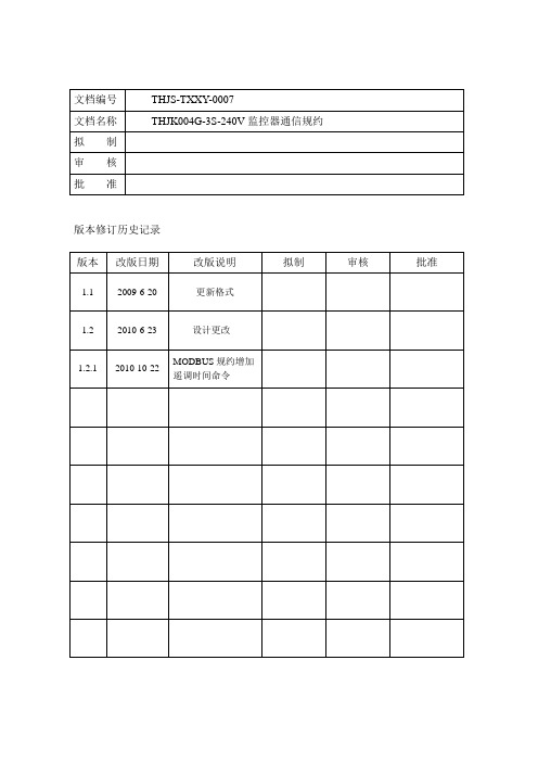
文档编号THJS-TXXY-0007文档名称THJK004G-3S-240V监控器通信规约拟制审核批准版本修订历史记录版本改版日期改版说明拟制审核批准1.1 2009-6-20 更新格式1.2 2010-6-23 设计更改1.2.1 2010-10-22 MODBUS规约增加遥调时间命令(一) MODBUS通信规约一、概述本文描述了THJK004G-3S-240V监控器数据上报的MODBUS协议通讯规约标准,应用于监控器向上位机设备上报数据时的通讯规约。
二、适用范围本规约适用于通合电子生产的THJK004G-3S-240V监控器与上位机之间进行串行通信,适用机型包括: THJK004G-3S-240V,是开发、测试此类监控器MODBUS协议通讯软件的依据。
三、物理接口接口标准为RS485。
通讯方式为异步串行通信,波特率支持:2400\ 4800 \9600,每帧数据10位(包括1位起始位、8位数据和1位停止位,无奇偶校验)。
四、命令格式1、遥测1.1 读取系统模拟量1)上位机下传信息:定义地址功能码STAR ADDR 寄存器个数CRC校验数据ADDR 03H 0000H 0014H CRC16字节数 1 1 2 2 2注:a)ADDR:监控设备地址。
范围:01H—99H,FF为广播地址(下同)。
b)START ADDR:为所操作寄存器的起始地址(下同)。
c) 校验码:前面所有字节的CRC16校验,采用标准CRC16校验,生成多项式为:X16+X12+X2+1(0X1005)。
2)微机监控器返回信息:定义地址功能码长度返回数据CRC校验数据ADDR 03H 28H DATA CRC 16字节数 1 1 1 40 2注:a)长度:微机监控器返回信息的字节数(下同)。
b)DATA定义:字节序号定义传输方式放大系数01-02 电池1电压H-L 1003-04 母线1电压H-L 1005-06 系统1电压H-L 1007-08 电池1电流H-L 1009-10 母线1电流H-L 1011-12 电池1温度H-L 1013-14 电池2电压H-L 1015-16 母线2电压H-L 1017-18 系统2电压H-L 1019-20 电池2电流H-L 1021-22 母线2电流H-L 1023-24 电池2温度H-L 1025-26 1路交流AB电压H-L 1027-28 1路交流AC电压H-L 1029-30 1路交流BC电压H-L 1031-32 2路交流AB电压H-L 1033-34 2路交流AC电压H-L 1035-36 2路交流BC电压H-L 1037-38 系统1电流H-L 1039-40 系统2电流H-L 101.2 读取母线绝缘1)上位机下传信息:定义地址功能码STAR ADDR 寄存器个数CRC校验数据ADDR 03H 0020H 0008H CRC 16字节数 1 1 2 2 22)微机监控器返回信息:定义地址功能码长度返回数据CRC校验数据ADDR 03H 10H DATA CRC 16字节数 1 1 1 16 2DATA定义:字节序号定义传输方式放大系数01-02 1段正对地电阻H-L 1003-04 1段负对地电阻H-L 1005-06 1段正对地电压H-L 1007-08 1段负对地电压H-L 1009-10 2段正对地电阻H-L 1011-12 2段负对地电阻H-L 1013-14 2段正对地电压H-L 1015-16 2段负对地电压H-L 101.3 读取单只电池电压1)上位机下传信息:定义地址功能码STAR ADDR 寄存器个数CRC校验数据ADDR 03H 0030H~00F4H 001CH CRC 16字节数 1 1 2 2 2注:起始地址0030H :1组1~28节电池; 004CH:1组29~56节电池;0068H :1组57~84节电池;0084H:1组85~112节电池;00A0H :2组1~28节电池; 00BCH:2组29~56节电池;00D8H :2组57~84节电池;00F4H:2组85~112节电池;2)微机监控器返回信息:定义地址功能码长度返回数据CRC校验数据ADDR 03H 38H DATA CRC 16字节数 1 1 1 56 2注:a)DATA定义:字节序号定义传输方式放大系数单位01-02 1#电池电压H-L 100 V …………………………55-56 28#电池电压H-L 100 V2、遥信1)上位机下传信息:定义地址功能码STAR ADDR 数据长度CRC校验数据ADDR 02H 0200H 0190H CRC 16字节数 1 1 2 2 22)微机监控器返回信息:定义地址功能码长度返回数据CRC校验数据ADDR 02H 32H DATA CRC 16字节数 1 1 1 49 2DATA定义:编号01 母线1电压(BIT0) 1-过压0-正常母线1电压(BIT1) 1-欠压0-正常电池1电压(BIT2) 1-过压0-正常电池1电压(BIT3) 1-欠压0-正常单体1电池(BIT4) 1-异常0-正常电池1过流(BIT5) 1-过流0-正常母线1绝缘(BIT6) 1-异常0-正常电池1均浮充状态(BIT7) 1-均充0-浮充编号02 母线2电压(BIT0) 1-过压0-正常母线2电压(BIT1) 1-欠压0-正常电池2电压(BIT2) 1-过压0-正常电池2电压(BIT3) 1-欠压0-正常单体2电池(BIT4) 1-异常0-正常电池2过流(BIT5) 1-过流0-正常母线2绝缘(BIT6) 1-异常0-正常电池2均浮充状态(BIT7) 1-均充0-浮充编号03 1#交流(BIT0) 1-失电0-正常1#交流(BIT1) 1-缺相0-正常1#交流(BIT2) 1-输入异常0-正常1#交流投切(BIT3) 1-投入0-切除2#交流(BIT4) 1-失电0-正常2#交流(BIT5) 1-缺相0-正常2#交流(BIT6) 1-输入异常0-正常2#交流投切(BIT7) 1-投入0-切除编号04 充电模块1~8通讯中断1-通讯中断0-正常编号05 充电模块9~16通讯中断1-通讯中断0-正常编号06 充电模块17~24通讯中断1-通讯中断0-正常编号07 充电模块25~30通讯中断(BIT0~BIT5)1-通讯中断0-正常编号08 综合测量模块(BIT0)1-通讯中断0-正常1#绝缘检测(BIT1)2#绝缘检测(BIT2)1#开关量模块(BIT3)2#开关量模块(BIT4)编号09 1~4电池巡检(BIT0~BIT3) 1-通讯中断0-正常编号10 1~8充电模块故障1-故障0-正常编号11 9~16充电模块故障1故障0-正常编号12 17~24充电模块故障1故障0-正常编号13 25~30充电模块故障(BIT0~BIT5)1故障0-正常编号14 1# 1~8 支路绝缘状态1-接地0-正常编号15 1# 9~16 支路绝缘状态1-接地0-正常编号16 1# 17~24支路绝缘状态1-接地0-正常编号17 1# 25~32支路绝缘状态1-接地0-正常编号18 1# 33~40支路绝缘状态1-接地0-正常编号19 1# 41~48支路绝缘状态1-接地0-正常编号20 1# 49~56支路绝缘状态1-接地0-正常编号21 1# 57~64支路绝缘状态1-接地0-正常编号22 2# 1~8 支路绝缘状态1-接地0-正常编号23 2# 9~16 支路绝缘状态1-接地0-正常编号24 2# 17~24支路绝缘状态1-接地0-正常编号25 2# 25~32支路绝缘状态1-接地0-正常编号26 2# 33~40支路绝缘状态1-接地0-正常编号27 2# 41~48支路绝缘状态1-接地0-正常编号28 2# 49~56支路绝缘状态1-接地0-正常编号29 2# 57~64支路绝缘状态1-接地0-正常编号30 1~8 开关1-告警/分位0-正常/合位编号31 9~16 开关1-告警/分位0-正常/合位编号32 17~24 开关1-告警/分位0-正常/合位编号33 25~32 开关1-告警/分位0-正常/合位编号34 33~40 开关1-告警/分位0-正常/合位编号35 41~48 开关1-告警/分位0-正常/合位编号36 49~56 开关1-告警/分位0-正常/合位编号37 57~64 开关1-告警/分位0-正常/合位编号38 65~72 开关1-告警/分位0-正常/合位编号39 73~80 开关1-告警/分位0-正常/合位编号40 81~88 开关1-告警/分位0-正常/合位编号41 89~96 开关1-告警/分位0-正常/合位编号42 充电模块31~38通讯中断1-通讯中断0-正常编号43 充电模块39~46通讯中断1-通讯中断0-正常编号44 充电模块47~54通讯中断1-通讯中断0-正常编号45 充电模块55~60通讯中断(BIT0~BIT5)1-通讯中断0-正常编号46 31~38充电模块故障1-故障0-正常编号47 39~46充电模块故障1故障0-正常编号48 47~54充电模块故障1故障0-正常编号49 55~60充电模块故障(BIT0~BIT5)1故障0-正常编号50 1~3INV模块通信中断(BIT0~BIT2)1-通讯中断0-正常1~3INV模块故障(BIT3~BIT5)1故障0-正常3、遥调1)上位机下传信息:定义地址功能码起始地址设置数据CRC校验数据ADDR 06H 0001H HL CRC 16字节数 1 1 2 2 2DATA定义:起始地址定义传输方式放大系数单位0001 浮充电压H-L 10 V 0002 均充电压H-L 10 V0003 电池充电限流 H-L 10 A2)微机监控器返回信息:原数据包返回定义 地址 功能码 起始地址 设置数据 CRC 校验 数据ADDR06H 0001H HL CRC 16 字节数 112224、遥控1)上位机下传信息:定义 地址 功能码 输出地址 VALUE CRC 校验 数据 ADDR 05 **XXH DATA CRC 16 字节数11222注:输出地址和DATA 的定义:**XXH **- 78H :开/关机信息 79H :均/浮充信息 XX-地址信息 FFH(系统内广播) DATA开机:0XFF00关机:0X0000 均充:0XFF00浮充:0X00002)微机监控器返回信息:定义 地址 功能码 遥控编号 VALUE CRC 校验 数据 ADDR 05H **XXH DATA CRC 16 字节数11222注:DATA 定义:00表示:接收正确 04表示:接收错误 5、遥调时间1)上位机下传信息:定义 地址 功能码 起始地址 寄存器数 字节数 设置数据 CRC 校验 数据 ADDR 10H 0004H 0007H 0EH HL CRC16 字节数 11221142DATA 定义:2)微机监控器返回信息:定义 地址 功能码 起始地址 寄存器数 CRC 校验 数据ADDR 10H0004H0007HCRC 16设置数据定义 传输方式 设置范围 1 特征码 H-L 固定为0xFFFF2 年 H-L 0-993 月 H-L 1-124 日 H-L 1-315 时 H-L 0-236 分 H-L 0-59 7秒H-L0-59THJS-TXXY-0007字节数 1 1 2 2 2。
FJ100-S3使用说明书(标)
FJ100-S3微机保护测控单元使用说明书1感谢您使用本公司产品。
使用前,请仔细阅读《用户手册》并请妥善保管以备将来之用如有疑问,请与本公司联系或访问请检查包装箱内各部件:智能保护测控单元用户手册固定螺丝(2套)产品合格证(贴于单元后部)本手册包含以下内容:JSY-2000系列微机保护测控单元简介FJ100-S3 微机保护测控单元使用说明书本手册内容更改或版本升级,恕不另行通知2目录一JSY-2000系列微机保护测控单元简介------------------5 1.1 主要特点-----------------------------------------------------5 1.2 主要技术指标-------------------------------------------------6 1.3 通信---------------------------------------------------------6 1.4 单元结构-----------------------------------------------------6 二FJ100-S3微机保护测控单元使用说明-----------------9 2.1 功能特点-----------------------------------------------------9 2.2 基本原理----------------------------------------------------10 2.2.1 差动速断--------------------------------------------------10 2.2.2 比例差动--------------------------------------------------10 2.2.3 过负荷保护------------------------------------------------11 2.2.4 低压保护--------------------------------------------------12 2.2.5 零序电流告警----------------------------------------------12 2.2.6 系统故障告警----------------------------------------------12 2.2.7 PT断线告警 -----------------------------------------------13 2.2.8 油压低1跳闸----------------------------------------------13 2.2.9油压低2告警-----------------------------------------------13 2.2.10 控制回路断线告警------------------------------------------13 2.2.11 断路器拒动告警--------------------------------------------13 2.3 操作说明-----------------------------------------------------14 2.3.1 定值的设定与修改-------------------------------------------14 2.3.2 功能投退开关-----------------------------------------------15 2.3.3 手动分合断路器---------------------------------------------16 2.3.4 主页键-----------------------------------------------------16 2.3.5 电压键-----------------------------------------------------16 2.3.6 电流键-----------------------------------------------------16 2.3.7 SOE键---------------------------------------------------------------------------------17 2.3.8 功率键--------------------------------------------------------------------------------18 2.3.9 定值键--------------------------------------------------------------------------------18 2.3.10 系统时钟设置---------------------------------------------------------------------18 2.3.11 工作指示灯------------------------------------------------------------------------19 2.3.12 通信指示灯------------------------------------------------------------------------19 2.3.13 告警灯------------------------------------------------------------------------------19 2.3.14 故障灯------------------------------------------------------------------------------1932.4 接线端子-------------------------------------------------------------------------------20 2.5 系统故障检查方法-------------------------------------------------------------------21 2.6 合闸前检查步骤----------------------------------------------------------------------21 2.7 故障分析方法-------------------------------------------------------------------------22 注:FJ100-S和FJ100-S3的功能相同。
EMCS专业知识教程
31
EMCS系统的控制策略
❖ 车站空调通风系统基础知识
❖ 湿空气的焓i
焓i的计算公式:
i =(1.01 + 1.84d)t + 2500d [ kJ/kg干空气]
式中:(1.01 + 1.84d) t 与湿空气温度有关,称 “显热”; 2500d 随含湿量d变化,称“潜热”。
温度t、含湿量d、相对湿度ψ、焓i都是独立的状态
普通集中式空调系统:低流速(v=8~12m/s)、单风 道、集中式,是典型、广泛应用的空调系统。 38
EMCS系统的控制策略
车站公共区空调通风系统(大系统)
1. 正常模式 ➢ I工况(最小新风量降温除湿工况) 特点:降温除湿,保证最小新风量,部分回风循环减耗。 ➢ II工况(全新风降温除湿工况) 特点:降温除湿,全新风,无回风循环。 ➢ III工况(全新风等温除湿工况) 特点:等温除湿,全新风,无回风循环。 ➢ IV工况(通风工况) 特点:全新风通风,冷水系统停止。
➢ 站厅层火灾
停止车站冷水系统;控制风管的相关风阀开/闭,向站台层 送风,停止向站厅层送风,站厅层进入排烟状态。使得站 厅层对地面、站台层形成负气压,阻止了烟雾向站台层蔓 延,并形成了地面楼梯通道的逃生气流通道。
40
EMCS系统的控制策略
设备用房通风空调系统(小系统)
1. 正常模式
与大系统的正常模式类似,有3-4种工况。
2. 火灾事故模式
设备用房发生火灾事故时,一般按单独房间情况处理。若 房间安装有GAS系统,关闭送风、排风阀,以便GAS释放气体 灭火。若不安装有GAS系统,同样要停止送风,进行排烟,防 止烟雾蔓延。
41
EMCS系统的控制策略
❖ 时间表控制
华为AirEngine 9700S-S无线接入控制器彩页-华为技术有限公司
华为AirEngine 9700S-S无线接入控制器彩页产品概述AirEngine 9700S-S是华为推出的面向中小型企业的小型盒式无线接入控制器(Access controller),最大可管理64个AP,同时集成千兆以太网交换机功能,实现有线无线一体化的接入方式。
可灵活配置无线接入点的管理数量,具有良好的可扩展性。
配合华为全系列802.11n/802.11ac/802.11ax无线接入点,可组建中小型园区网络、企业办公网络、无线城域网络、热点覆盖等应用环境。
AirEngine 9700S-S产品主要特性高容量、高性能设计●AirEngine 9700S-S最大可管理64个AP,满足中小型园区的管理需求;●提供2个10GE光口, 10个GE电口,可转发4Gbps的数据;SmartRadio实现AP空口优化●智能漫游负载均衡技术:利用智能漫游负载均衡算法,在用户漫游后对组网内AP进行负载均衡检测,调整各个AP的用户负载,提升网络稳定性。
●智能频段动态调整技术:利用DFA算法(Dynamic Frequency Assignment)自动检测邻频和同频的信号干扰,识别2.4G 冗余射频,通过AP间的自动协商,自动切换(双5G款型)或关闭冗余射频,降低2.4G同频干扰,增加系统容量。
●智能冲突优化技术:利用动态EDCA和Airtime调度算法,对每个用户的无线信道占用时间和业务优先级进行调度,确保每个用户业务有序调度且相对公平的占用无线信道,提升业务处理效率和用户体验。
角色多样●内置Portal/AAA服务器,可为用户提供Portal认证/802.1X服务,降低用户投资成本。
组网灵活●WLAN AC支持直连式,旁挂式和桥接/Mesh组网模式,同时支持数据集中转发和本地转发模式。
●支持跨二层、三层AP/WLAN AC间组网,同时支持AP在私网、WLAN AC在公网的NAT穿越部署。
●兼容管理华为全系列802.11n、802.11ac和802.11ax AP, 实现802.11n、802.11ac和802.11ax AP的混合组网,保护用户投资。
JK02-03监控说明书
直流电源屏JK02监控器使用说明书目录1前言-------------------------------------------------------------------------------------------------------2产品特点------------------------------------------------------------------------------------------------- 3功能介绍------------------------------------------------------------------------------------------------- 4选型说明-------------------------------------------------------------------------------------------------5工作原理------------------------------------------------------------------------------------------------1)电池充电管理-----------------------------------------------------------------------------------------2)温度补偿----------------------------------------------------------------------------------------------- 6产品结构及安装尺寸---------------------------------------------------------------------------------- 7接线端口定义-------------------------------------------------------------------------------------------8显示及操作说明----------------------------------------------------------------------------------------1)显示及按键说明--------------------------------------------------------------------------------------2)信息查询-----------------------------------------------------------------------------------------------a)当前故障--------------------------------------------------------------------------------------------b)模块数据--------------------------------------------------------------------------------------------c)交流数据--------------------------------------------------------------------------------------------d)直流数据--------------------------------------------------------------------------------------------e)历史故障--------------------------------------------------------------------------------------------f)开关信息--------------------------------------------------------------------------------------------g)电池巡检--------------------------------------------------------------------------------------------h)绝缘监测--------------------------------------------------------------------------------------------3)参数设置-----------------------------------------------------------------------------------------------a)模块设置--------------------------------------------------------------------------------------------b)交流设置--------------------------------------------------------------------------------------------c)直流设置--------------------------------------------------------------------------------------------d)开关设置--------------------------------------------------------------------------------------------e)电池巡检--------------------------------------------------------------------------------------------f)绝缘监测--------------------------------------------------------------------------------------------g)通信模块--------------------------------------------------------------------------------------------h)逆变模块--------------------------------------------------------------------------------------------i)节点输出--------------------------------------------------------------------------------------------j)通信设置-------------------------------------------------------------------------------------------- k)修改时间-------------------------------------------------------------------------------------------- l)修改密码-------------------------------------------------------------------------------------------- m)模块控制-------------------------------------------------------------------------------------------- n)电池管理--------------------------------------------------------------------------------------------9安装说明------------------------------------------------------------------------------------------------附录A电池巡检单元简介-------------------------------------------------------------------------------- 附录B绝缘检测单元简介--------------------------------------------------------------------------------1前言应广大客户要求,我公司新推出一款性能价格比极高的简易电力电源监控系统---RHD02-03系统。
- 1、下载文档前请自行甄别文档内容的完整性,平台不提供额外的编辑、内容补充、找答案等附加服务。
- 2、"仅部分预览"的文档,不可在线预览部分如存在完整性等问题,可反馈申请退款(可完整预览的文档不适用该条件!)。
- 3、如文档侵犯您的权益,请联系客服反馈,我们会尽快为您处理(人工客服工作时间:9:00-18:30)。
Professional achievement of excellenceHF Switching DC Power Supply System1 attachment:Electric power supervisory system technical manualSI CHUAN AHAIFA ELECTRIC CO.,LTD.OF CHINAChapter 1 Overview1.1 General descriptionThe electric power supervisory system considered fully the electrical power system application multiplicity, has the host unit and the RTU unit has used the modulation design concept, the host unit and the RTU unit may combine freely. All RTU unit external dimensions are consistent, are advantageous for the installment. The host unit is THJK004G-3S. The RTU unit including ZHCL unit, DCXJ unit, KGL unit, JYJC unit. .Monitoring equipment specification table as shown in Table 1-1.Name Model Function summaryHOST unit THJK004G-3S Blue color 320*240 pixels LCD, screen-touch type monitorZHCL unit ZHCL-3Examines 2 AC voltage Examines 6 DC voltage, 4 current,2 temperature Examines 32 DI, provides 8 DODCXJ unit DCXJ-55 Examines 55 batteries the voltages, 2 temperatureJYJC unit JYJC-64 Examines 2 bus insulation, 64 branch insulationKGL unit KGL-64 Examines 64 DI, provides 8 DOTable 1-1 equipment specification table1.2 Function introduction1、THJK004G-3S HOST unitBlue color 320*240 pixels LCD, screen-touch type monitor.The screen-touch type operation is advantageous for the establishment parameter and the inquiry information.Provides RS485, RS232; Provides protocol CDT, MODBUSThe real-time clock demonstrated, after power failure clock normal operation.May save 200 Fault logs, 48 work logs, after the power failure the information does not lose.Battery charge management function.2、ZHCL-3 unitExamines 2 AC voltage .Examines 6 DC voltage, 4 current,2 temperature.Examines 32 DI, provides 8 group switch quantity output.Examines 2 bus insulation.Can control 5/7 degree V-drop unit.Being suitable uses in 2 group of batteries, in 2 group of battery charger system.3、DCXJ-55 unitExamines 55 batteries which rated voltage is 2V .Examines 1 battery temperatureBeing suitable uses in examining 54/108 batteries.4、JYJC-64 unitExamines 2 bus insulationExamines 64 branch insulationBeing suitable uses in the system which branch quantity is more than 32.5、KGL-64 unitExamines 64 DI.Provides 8 group switch quantity output.1.3 Use environmentThe work ambient temperature is not lower than - 5℃, is not higher than +40℃, the equipment saves ambient temperature permission for - 10℃~+60℃.The work environment maximum relative humidity does not surpass 90% (ambient temperature is 25℃).The movement place non-electric conduction dust, does not have the dipping and the destruction insulation gas or the steam.Uses originally in the room infield.If has the special request please when the ordering propose that, guaranteed this product can work reliably.Chapter 2 THJK004G-3S2.1Features2.1.1 Human interfaceBlue color 320*240 pixels LCD, touch-press type monitor.The touch -press type operation is advantageous for the establishment parameter and the inquiry information.2.1.2 Fault informationEach kind of Fault information direct-viewing clear, most demonstrates 30.May save 200 Fault logs, after the power failure the information does not lose.When Fault occurs, the LCD screen light, the buzzer makes the warning sound.May establish warning threshold.2.1.3 Battery managementAutomatically manages the battery charge.May examine 2 groups of 108 cellsMay simultaneously carry on the management to 2 groups of batteries.2.1.4 InsulationMay configure 2 JYJC-64 unit, examines 2 bus, 128 branch.When has not configured JYJC unit, through ZHCL unit examination bus insulation.2.1.5 Switch input & outputThe user may define switch input style、show style, first label.Provides 8 switch output.May configure 2 KGL-64 unit.2.1.6 Host communicationInterface could select RS232 or RS485.Protocol could select CDT or MODBUS.Baud rate could select 2400、4800 or 9600.Address range 01~99.2.1.7 OthersMay save 48 work logs, after the power failure the information does not lose.If there is no key-press operation within 4 minute, then runs screen protection.The real-time clock demonstrated, after power failure clock normal operation.Note:The display datas of supervisory screen in this manual are for reference only .the final parameter of the host unit of this projet must be set by our company’s personnel.2.2 THJK004G-3S interfaceFigure 2-1 THJK004G-3S frontFigure 2-2 THJK004G-3S backIdentify DescriptionRUN When power on,the green LED light.ALM When there is fault,the red LED twinklesRST Reset key.COM2 RTU RS485 interface.COM1 Host computer communication RS232 1-RXD 2-TXD 3-GND.RS485 4-485A 5-485B.Power Power supply,range:90~300VDC.Table 2-1 THJK004G-3S interface Explanation2.3 THJK004G-3S operate manual2.3.1 Main menuWhen system connection power source enters the main interface. This interface displays system time and the battery, control bus basic information.Power Monitor08-08-10 12:00:00NO FaultBatt : 134.0V Curr : 0.0A Ctrl : 110.0V Load: 0.0A State : floatInfo InqPara Set Operate Password2.3.2 Info queryThis is information query menu.Information08-08-10 12:00:00Back2.3.2.1 AC infoThis is AC information menu. Inquire AC voltage at here. 2.3.2.2 DC infoThis is DC information menu. Inquire DC information at here. 2.3.2.3 BatteryAC info DC info Battery InsulationRectifier Work log Fault log FaultThis is battery information menu. Inquire battery information at here.2.3.2.4 InsulationThis is insulation information menu. Inquire insulation information at here.2.3.2.5 RectifierThis is rectifier information menu. Inquire rectifier information at here. 2.3.2.6 Work logThis is work log information menu. Inquire work log information at here.2.3.2.7 Fault logThis is Fault log information menu. Inquire Fault log information at here.2.3.2.8 FaultThis is Fault information menu. Inquire Fault information at here.2.3.3 Para setThis is parameter set menu.Para set08-08-10 12:00:00Back2.3.3.1 System ParaTouch "Sys para", enter system parameter interface.system para08-08-10 12:00:00V-drop Unit : NO Current Range: 100A KGL Unit : 01 JYJC Unit : 01 Charging Unit : 03 DCXJ Unit : 01 48V Unit : 00 Ctrl Unit : 001 2 3 4 5 6 7 8 9 0 + - .ENTESCBackV-drop unit :Whether use the V-drop function of ZHCL. Current range :The max current that ZHCL could measured. KGL unit : KGL unit quantum ,range 0~2. JYJC unit :JYJC unit quantum ,range 0~2.Charge unit :Charge rectifier unit quantum ,range 0~15. DCXJ unit :DCXJ unit quantum ,range 0~2. Ctrl unit :Control rectifier unit quantum ,range 0~5. 48V unit :48V rectifier unit quantum ,range 0~5.Sys para Rectifier Charge Fault DCXJ Switch JYJCOthers2.3.3.2Charge ParaTouch"charge",enter charge parameterinterface.Battery charge para 08-08-10 12:00:00Rated capacity: 1100AH Charge current: 220A Float to boost: 176A Boost to float: 66A Tail charge: 3H Timing boost : Yes Boost interval: 180D Comp enter: 25℃1 2 34 5 67 8 90 + -. ENT ESC PageDown BackBattery charge para 08-08-10 12:00:00Comp rate : 0.3V/℃Max boost: 010H Discharge voltage: 200V Max discharge time: 010H 1 2 3 4 5 6 7 8 9 0 + - . ENT ESCPageUp BackRated capacity:The capacity of battery .Charge current:The charge current limitation of battery.Float to boost:The criterion of float to boost.Boost to float:The criterion of boost to float.Tail charge :Tail charge time,range 0~9 hour.Comp center:Compensation center,Compensation voltage=(center - temperature)× rate Max boost :Max boost time,range 0~99 hour.Discharge voltage:110V level:93~120V;220V level:186~240V.Max discharge time:Range 0~30 hour.Charge course goes on according to the following curve:1.The normal course curve of the battery charge:Boost stage can be divided into three stages: constant current, constant voltage, tail-charge. When the charge current is greater than " Float to boost", after 20 seconds, if the charge current is still greater than " Float to boost ", then enter boost charge, and begin to time. If the battery is relatively deep in feed, it is great to charge current, enter constant current charge stage. As time goes on, the battery voltage of the battery rises to boost charge voltage gradually, charge current is reduce to below the battery limiting current, the battery enter constant voltage charge stage. Charge current continue to reduce, when smaller than "Boost to float ", after 20 seconds, boost count-down to begin, enter tail charge stage, after reaching tail “Tail-charge time”, enter float state. Certainly, boost tim e smaller than the “Max boost time”, as boost time exceed the “max boost time” while being whole, no matter at boost stage, should transfer to float state.2.The course curve of float for a long time:Every a few months, JK004G-3S automatically controls the battery to be boosting.3. The charge course curve of the AC is broken:While AC power resumed, the JK004G-3S controls the charge rectifier to enter the float state. If battery discharge relatively deed, battery charge current greater than "Floating to boost", the JK004G-3S controls the charge module to enter boost state, charge according to the course curve of the battery charge normally.2.3.3.3 DCXJ ParaTouch"DCXJ",enter DCXJ Unit parameterinterface.DCXJ para 08-08-10 12:00:00DCXJ type: DCXJ-19 Cell quantum: 018 Over voltage: 15.0V under voltage: 10.0V End cell: NO End over: 2.5V End under: 1.8V 1 2 3 4 5 6 7 8 9 0 + - . ENT ESCBackDCXJ type:DCXJ unit type could select“DCXJ-19”or“DCXJ-55”.Cell quantum:When select“DCXJ-19”,range 1-18;When select “DCXJ-55”,range 1-110;over voltage:range 0.1-16V.under voltage:range 0.1-16V.End cell:When select“DCXJ-19”,this option is true.End over:End over voltage,w hen select“DCXJ-19”,this option is true.Range0.1-16V.End under:End under voltage,w hen select“DCXJ-19”,this option is true.Range0.1-16V.2.3.3.4 JYJC paraTouch"JYJC",enter JYJC Unit parameterinterface.1#JYJC para 08-08-10 12:00:00JYJC type : JYJC-32 Label : 001 Ctrl-Sub : 15 Drive-Sub : 10 1 2 3 4 5 6 7 8 9 0 + - . ENT ESCBackJYJC type:JYJC unit type could select “JYJC-32”or“JYJC-64”. Label:The first branch label. Range 0-500.Ctrl-Sub:Control bus branch quantum.Drive-Sub:Drive bus branch quantum.2.3.3.5 RectifierTouch"Rectifier",enter Rectifier parameterinterface.Rectifier para 08-08-10 12:00:00Rated voltage: 110V Rated current: 40A Float voltage: 134V Boost voltage: 143V Over voltage :175V Under voltage: 99V 1 2 3 4 5 6 7 8 9 0 + - . ENT ESCBackRated voltage:Could select 110V or 220V.Rated current:Could select 3A,5A,7A,10A,20A,30A,40A. Float voltage:110V level:93~175V;220V level::186~350V.Boost voltage:110V level:93~175V;220V level::186~350V. Over voltage:Charge rectifier DC output over voltage threshold. Under voltage:Charge rectifier DC output under voltage threshold.2.3.3.6 FaultThis is Fault parameter menu. Set Fault parameter at here.Fault para 08-08-10 12:00:00AC ov-voltage: 478V AC un-voltage: 353V Bus ov-voltage: 115V Bus un-voltagee: 94V Batt ov-voltage:143V Batt un-voltage: 94V Batt ov-current: -A Bus insulation: 030KΩ1 2 3 4 5 6 7 8 9 0 + - . ENT ESCBackAC ov-voltage:AC over voltage,Range AC under voltage ~480V.AC un-voltage:AC under voltage,Range 160V~ AC over voltage.Bus ov-voltage:Bus over voltage,110V level 93~175V;220V level:186~350V.Bus over voltage:110V level:93~175V;220V level:186~350V.Batt ov-voltage:Battery over voltage,110V level:93~175V;220V level:186~350V. Batt un-voltage:Battery under voltage,110V level:93~175V;220V level:186~350V. Batt ov-current:Charge over current,Range 0~400A.Bus insulation:Insulation Fault,Range 1~99KΩ.2.3.3.7 SwitchSwitch para08-08-10 12:00:00Back1、Switch outputSwitch output08-08-1012:00:00K1: System Fault K2: Rectifier Fault K3: Insulation Fault K4: AC Fault K5: Battery Fault K6: Control Fault K7: Switch Fault K8: Battery floatBackSwitch output :Could define K1~K8.Range :System Fault 、Rectifier Fault 、InsulationFault 、AC Fault 、Battery Fault 、Control Fault 、Switch Fault 、Battery float 、Battery boost 、Battery discharge 、Bank 1 float 、Bank 1 boost 、Bank 1 discharge 、Bank 2 float 、Bank 2 boost 、Bank 2 discharge 、Rectifier 1 Fault 、Rectifier 2 Fault 、Rectifier 3 Fault 、Rectifier 4 Fault.Output ZHCL 1#KGL2#KGL2、Switch inputZHCL switch input 08-08-10 12:00:00quantum : 10 Show type: Fault Input type : NC First label : 001 others : 051 2 34 5 67 8 90 + -. ENT ESC PageDown Backswitch quantum:Do not include other switch.show type:Range: Fault or state.input type:Range: NO or NC.First label:The first switch’s label.ZHCL switch input 08-08-1012:00:00other01: AC switchother02: DC switchPageUP Backother switch:Range 0~8;other switch range: AC switch、DC switch、DC fuse、Battery switch、Battery fuse、discharge switch、Inverter switch、Switch、Arrester、Inverter、DC/DC unit、Battery、V-drop unit、Insulation、fuse unit、1# AC switch、2# AC switch、1# DC switch、2# DC switch、1# DC fuse、2# DC fuse、1# Battery fuse、2# Battery fuse、1# Battery switch、2# Battery switch、1# discharge switch、2# discharge switch.Other switch’s input type is NC and show type is Fault.2.3.3.8 others1、CommunicationComm para 08-08-10 12:00:00Address : 01 Baud rate: 9600 Protocol : CDT-91 1 2 3 4 5 6 7 8 9 0 + - . ENT ESC返回Address:It’s THJK004G-3S’s address,range 01~99.Baud rate:Range 2400、4800、9600.Protocol:CDT or MODBUS.After modified, user should resetTHJK004G-3S.Protocol CDT uses RS232,protocol MODBUS uses RS485.2、CalanderIN this menu, set the system calendar.3、othersOthers 08-08-10 12:00:00Contrast adjust:70 Clear Fault log: NO Clear work log: NO Clear discharge log:NO 1 2 3 4 5 6 7 8 9 0 + - . ENT ESCBackContrast adjust:Adjust the LCD’s contrast. Clear Fault log:Clear the Fault log.Clear work log:Clear the work log.Clear discharge log:Clear the discharge log.2.3.4 Sys operateSys operate 08-08-10 12:00:00Charger: ON Battery: Float 1 2 3 4 5 6 7 8 9 0 + - . ENT ESCBackCharger operate:Operate the charge rectifier to be on or off.Battery operate:Operate the battery to be float、boost or discharge.Some options about discharge operationA:Discharge voltage:Para set Battery Discharge voltageB:Max discharge time:Para set Battery Max discharge timeC:discharge operation:Sys operate Battery operateThe process of battery discharge operationAfter user have select discharge operation, the THJK004G-3S will send “Discharge voltage” to charge rectifier, the rectifier’s out voltage becomes Discharge voltage’,because the rectifier’s out is below battery’s voltage, so battery starts discharge. While either or both the two case is reached, the discharge operation is stopped and becomes to float. A:The battery’s voltage reaches“Discharge voltage”.B:The discharge time reaches “Max discharge time”.Because the charge rectifier does not shut down, so the battery would not over discharge.2.3.5 PasswordThe initial password is 0000,user can set new password at here.Chapter3 ZHCL-3 Unit4.1 OverviewZHCL-3 unit measures necessary data, and transfers it to host by RS485.AC measure:6 branch circuits.DC measure:6 DC voltage,4 current,2 temp,2 bus insulation.Switch input:32 switch input.Switch output:8 switch output,there K1、K2、K3 can used to control V-drop unit.4.2 Interface ExplanationZHCL-3assembly drawing see Figure 3-1.Identify DescriptionSI 1 NO.1 switch input ……32 NO.32 switch inputCOM Switch input common point.K1 Relay output 1,NO.Capacity AC250V/5A,DC30V/5A.……K8 Relay output 8,NO.Capacity AC250V/5A,DC30V/5A.K9 AC 1 control.Capacity AC250V/5A,DC30V/5A.K10 AC 2 control.Capacity AC250V/5A,DC30V/5A.AC1 AC1 voltage. Range:0~500V AC;measure precision≤±1.0%. AC2 AC2 voltage.KM1 V Control bus 1 voltage. Range:0~300VDC;measure precision≤±0.5%. HM1 V Drive bus 1 voltage.Batt1 V Battery 1 voltageKM2 V Control bus 2 voltage.HM2 V Drive bus 2 voltage.Batt2 V Battery 2 voltageKM1 I Control bus 1 current Range:0~100A.measure precision≤±1% BATT1 I Battery 1 currentKM2 I Control bus 2 currentBatt2 I Battery 2 currentTemp1 Battery 1 temperature Range:-10℃~+100℃.measure precision≤±3℃. Temp2 Battery 2 temperatureAddr ZHCL-3 unit address,ON position is 0,inverse position is 1.RS485 RS485 interface.Power Power input,Range:90~300VDC.Table 4-1 ZHCL-3 Interface Explanation4.3 AC controlFigure 4-1 AC control schematicWhile AC power on,,K9、JK2 is NC contact,The Q1 coil adds on the AC voltage,Q1 attracts gathers, AC1 start working, and JK1 switch-off.When AC1 is fault,K9 switch-off,Q1 coil loses the AC voltage,Q1 switch-off,AC1 cut off,and JK1 attracts gathers;After 4~6 second,if AC2is normal,K10 attracts gathers,Q2 coil adds on the AC voltage,Q2 attracts gathers,AC2 is doing to work.4.4 Current SensorSee Figure 3-2.4.5 Temperature SensorSee Figure 3-3.4.6 Switch inputSee Figure 3-4.4.7 Switch outputSee Figure 3-5, Figure 3-6.Chapter 4 DCXJ-55 Unit6.1 OverviewDCXJ-55 unit measures cell’s voltage、temperature, and transfers it to host by RS485. Measures 55 cell’s voltage.Measures 2 temperature.6.2 Interface ExplanationFigure 6-1 DCXJ-55 Assembly drawingIdentify Description0 NO.1 cell negative.( battery’s negative )Range:0~4V.1 NO.1 cell positive.(NO.2 cell negative )2 NO.2 cell positive.(NO.3 cell negative )……55 NO.55 cell positive.battery’s positive)Temp1 Temperature sensor 1 interface Range:-10℃~+100℃.Temp2 Temperature sensor 2 interfaceAddr Unit address,ON position is 0,inverse position is 1..RS485 RS485 interface.Power Power supply,range 90~300VDC.Table 6-1 DCXJ-55 Interface Explanation6.3 Wiring SchematicFigure 6-2 DCXJ-55Wiring schematic1 2 3 4Group1 1# 0 0 0 0 2# 0 0 0 1Group2 3# 0 0 1 0 4# 0 0 1 1 Table 6-2 DXCJ-55 address tableChapter 5 JYJC-64 Unit7.1 OverviewJYJC-64 unit measures 2 bus insulation、64 branch insulation, and transfers it to host by RS485.Measures 2 bus insulation.Measures 64 branch insulation.Measure c ycle:≤60S.7.2 Interface ExplanationFigure 7-1 JYJC-64 Assembly drawingIdentify Description1 NO.1 branch sensor output…………64 NO.64 branch sensor output+12V branch sensor power supply +12VGND branch sensor power supply GND-12V branch sensor power supply -12VK1 Relay output, NO.Capacity AC250V/5A,DC30V/5A.KM2 Control bus 2 positiveHM2 Drive bus 2 positive-M2 Bus 2 negati veKM1 Control bus 1 positiveHM1 Drive bus 1 positive-M1 Bus 1 negati veEarthCOM parallel operation interface.Addr Unit address,ON position is 0,inverse position is 1..RS485 RS485 interface.Power Power supply,range 90~300VDC.Table 7-1 JYJC-64 Interface Explanation7.3 Parallel operation interfaceWhen use 2 JYJC-64,the 2 JYJC-64 should use parallel operation model..Figure 7-2 Parallel operation mode7.4 Branch sensorFigure 7-3 Branch Sensor Wiring schematicChapter 6 KGL-64 Unit9.1 OverviewKGL-64 unit measures switch input signal, and transfers it to host by RS485.64 switch input.8 relay output.9.2 Interface ExplanationFigure 9-1 KGL-64 Assembly drawingIdentify Description1 N.O 1 switch……64 N.O 64 switchCOM Switch input common point.K1 Relay output 1,NO.Capacity AC250V/5A,DC30V/5A.… …K8 Relay output 8,NO.Capacity AC250V/5A,DC30V/5A.Addr Unit address,ON position is 0,inverse position is 1..RS485 RS485 interfacePower Power input,range: 90~300VDC.Table 9-1 KGL-64 Interface Explanation。