力驱LEM长行程推拉电磁铁选型手册
lambda电磁铁驱动板说明书V2
LAMBDA电磁铁驱动板说明书V2 本驱动板主要用于驱动控制电磁铁,电磁阀之类的由电能转换成磁能的器件。
使这类器件控制更智能化。
驱动这类器件时,有以下特点:1.电磁铁,电磁阀之类的电磁零件长时间通电时,工作器件不发热。
解决普通电磁铁不能长时间通电的问题。
常规的电磁铁长时间通电,线圈会发热,热量达到一定的时候,磁场的磁芯会磁饱和,温度越高,磁饱和点就越低,这样磁场就会越小,越没力。
当温度高到线圈所承受的最高点时,线圈就会损坏。
所以一般的电磁铁都是不能长时间通电的。
2.可以控制电磁铁的推力与锁定的力度大小。
通过调节板上的“PWM脉宽”电位器,可以控制板上到电磁铁的力度。
调”FRQ频率”电位器,可以调整电磁铁工作的频率点,用来匹配不同型号的电磁铁的工作频率力度点与工作噪声.2个电位器组合起来调整,可以匹配各种不同型号的电磁铁.3.控制简单。
接入3条线即可,电源供电正负与一条控制线,控制是接低电平有效。
默认供电是7-30V。
可以输入12V或24V电源去控制12V或24V标称的电磁器件。
如果要控制5V,48V或其他电源电压的电磁器件,可以与我们联系订制。
控制线接0V时工作。
悬空或接高电平时不工作。
4.工作原理:通电瞬间,如果有控制信号,驱动板会以电磁铁设计的最大推力启动电磁铁,当电磁工作稳定后,电磁铁进入锁定工作状态,锁定力度的推拉力度改由板上的电位器控制。
一般来说,锁定力度设在最大力度的40%-50%左右时,电磁铁都可以稳定的锁定了。
5.产品的V2版本增加了预留了OCP 过流保护,OTP 过温度保护功能,OCP过流保护是用来预防负载短路保护用的,可以设置电位器调节,过电流保护点.一般来说直接用默认设置即可,不需要调节.关于OTP 过温度保护功能,这个要配合温度电阻NTC10K 型号来使用.边上的2个白色插头是用来插10K NTC 热敏电阻的,这个热敏电阻可以固定到电磁铁上或其它用电的地方,只要这个探测到温度高到设定点,电磁铁就会关闭,该功能是选配的,默认发货是没有的.如果需要,请与客服联系. 产品展示:备注:下图为V1的老款产品,接口控制一样的,老款产品已经停产,新版的产品功能更加强大,性能更加稳定.新款的产品比来款的尺寸宽度要大一倍,长度一样的都是72MM.输出负调节锁定力设正跳针,基本不用调。
澳特Eaton Moeller系列MSC-DEA DOL电动启动器168805说明书

Eaton 168805Eaton Moeller® series MSC-DEA DOL starter, 380 V 400 V 415 V: 0.37 kW, 100 kA, Ir: 1 - 4 A, Connection to SmartWire-DT: yes, 24 V DC, DC Voltage, Screw terminalsGeneral specificationsEaton Moeller® series MSC-DEA DOL starter168805128 mm242 mm 45 mm 1.1 kgVDE 0660 IEC/EN 60947-4-1MSC-DEA-4-M17(24VDC)Product NameCatalog Number Product Length/Depth Product Height Product Width Product Weight Certifications Model CodeShort-circuit releaseTemperature compensated overload protection AdjustableScrew terminalsIn conjunction with PKE-SWD-32 SmartWire DT PKE module Yes2700 (Class 10) AC-4 cycle operation, Main conducting paths 500 (Class 5) AC-4 cycle operation, Main conducting paths 900 (Class 15) AC-4 cycle operation, Main conducting paths 1000 (Class 20) AC-4 cycle operation, Main conducting paths For all combinations with an SWD activation, you need not adhere to the minimum current flow times and minimum cut-out periods.Note: Going below the minimum current flow time can cause overheating of the load (motor).≤ 500 ms, main conducting paths, AC-4 cycle operationIP00NEMA OtherDirect starterDIN rail11 A4 AFitted with: Functions ClassConnectionConnection to SmartWire-DTCoordination typeCurrent flow times - minCut-out periods - minDegree of protectionModelMounting methodNumber of auxiliary contacts (normally closed contacts) Number of auxiliary contacts (normally open contacts) Overload release current setting - minOverload release current setting - maxIII3Other bus systems6000 V ACAlso motors with efficiency class IE3 Starter with electronic trip unitDC -25 °C55 °C4 A4 A4 A0.75 kW3.6 kW2.2 kW230 - 415 V AC50 A 100000 A 186 A 0.86 W 0 V0 V0 V0 V24 VOvervoltage categoryPollution degreeProtocolRated impulse withstand voltage (Uimp) Suitable forTypeVoltage type Ambient operating temperature - minAmbient operating temperature - maxRated operational current (Ie)Rated operational current (Ie) at AC-3, 380 V, 400 V, 415 V Rated operational current (Ie) at AC-3, 500 VRated operational power at AC-3, 220/230 V, 50 HzRated operational power at AC-3, 380/400 V, 50 HzRated operational power at AC-3, 500 V, 50 HzRated operational voltageRated conditional short-circuit current (Iq), 500 VRated conditional short-circuit current (Iq), type 2, 380 V, 400 V, 415 VShort-circuit release (Irm) - max Power consumption (sealing) at DCRated control supply voltage (Us) at AC, 50 Hz - min Rated control supply voltage (Us) at AC, 50 Hz - max Rated control supply voltage (Us) at AC, 60 Hz - min Rated control supply voltage (Us) at AC, 60 Hz - max Rated control supply voltage (Us) at DC - minRated control supply voltage (Us) at DC - max24 VEquipment heat dissipation, current-dependent Pvid1.5 WHeat dissipation capacity Pdiss0 WHeat dissipation per pole, current-dependent Pvid0.5 WRated operational current for specified heat dissipation (In)4 AStatic heat dissipation, non-current-dependent Pvs0.86 W10.2.2 Corrosion resistanceMeets the product standard's requirements.10.2.3.1 Verification of thermal stability of enclosuresMeets the product standard's requirements.10.2.3.2 Verification of resistance of insulating materials tonormal heatMeets the product standard's requirements.10.2.3.3 Resist. of insul. mat. to abnormal heat/fire by internalelect. effectsMeets the product standard's requirements.10.2.4 Resistance to ultra-violet (UV) radiationMeets the product standard's requirements.10.2.5 LiftingDoes not apply, since the entire switchgear needs to beevaluated.10.2.6 Mechanical impactDoes not apply, since the entire switchgear needs to beevaluated.10.2.7 InscriptionsMeets the product standard's requirements.10.3 Degree of protection of assembliesDoes not apply, since the entire switchgear needs to beevaluated.10.4 Clearances and creepage distancesMeets the product standard's requirements.10.5 Protection against electric shockDoes not apply, since the entire switchgear needs to beEaton Corporation plc Eaton House30 Pembroke Road Dublin 4, Ireland © 2023 Eaton. Wszelkie prawa zastrze żone.Eaton is a registered trademark.All other trademarks areproperty of their respectiveowners./socialmediaevaluated.Does not apply, since the entire switchgear needs to be evaluated.Is the panel builder's responsibility.Is the panel builder's responsibility.Is the panel builder's responsibility.Is the panel builder's responsibility.Is the panel builder's responsibility.The panel builder is responsible for the temperature rise calculation. Eaton will provide heat dissipation data for the devices.Is the panel builder's responsibility. The specifications for the switchgear must be observed.Is the panel builder's responsibility. The specifications for the switchgear must be observed.The device meets the requirements, provided the information in the instruction leaflet (IL) is observed.Simple, flexible and safe! Distribution system for motor-starter combinations DA-DC-00004109.pdf DA-DC-00004245.pdf eaton-manual-motor-starters-dol-starter-msc-d-dimensions.epseaton-manual-motor-starters-mounting-msc-d-dol-starter-3d-drawing.eps eaton-manual-motor-starters-dol-starter-msc-d-3d-drawing-002.eps DA-CE-ETN.MSC-DEA-4-M17(24VDC)IL03402010Z DA-CS-msc_de_bg2DA-CD-msc_de_bg2eaton-manual-motor-starters-msc-d-dol-starter-wiring-diagram.eps 10.6 Incorporation of switching devices and components 10.7 Internal electrical circuits and connections 10.8 Connections for external conductors 10.9.2 Power-frequency electric strength 10.9.3 Impulse withstand voltage 10.9.4 Testing of enclosures made of insulating material 10.10 Temperature rise10.11 Short-circuit rating10.12 Electromagnetic compatibility10.13 Mechanical functionBroszuryCertyfikatyDWGeCAD modelInstrukcje monta żu mCAD model Schematy po łączeń。
利海尔轨道受力推挽机商品说明书
Pressinformation Liebherr opens new logistics centre at Oberopfingen, Germany∙Spare parts supplies for the Earthmoving Equipment division will be managed froma new central location, and other construction machinery divisions are set to follow. ∙Modern technology guarantees reliable supplies for Liebherr customers.∙Ideal connections to transport infrastructure and major Liebherr production facilities.Kirchdorf an der Iller (Germany), 19 June 2015 –Around 1,000 guests attended the opening ceremony of the Liebherr Group's new logistics centre on 19 June 2015 at Oberopfingen, Germany. From the district of Kirchdorf an der Iller, the family-run company will in the future supply customers around the world with spare parts for earthmoving machines.The logistics centre is the new central hub from which Liebherr customers around the world will be supplied with spare parts for wheeled and crawler excavators, wheel loaders, crawler tractors and other earthmoving machines. Until 2013, the management of spare parts supplies was more decentralised. In view of the growing product range and increasingly complex material flows, Liebherr decided to centralise its system, initially organising it from smaller, existing warehouses. In mid-2013, the company finally began to build the new, larger and more modern logistics centre.“Our customer now get their spare parts faster,” explains Martin Barth, managing director of the operating company Liebherr-Logistics GmbH. “This important step guarantees that we will remain competitive in the future.” Around 1,000 guests at the opening ceremony –including the Liebherr family –were given an insight into the technology, proportions and processes. In his address, Dr. Heiko Schmid, district chief executive of the Biberach district, stressed the importance of the Liebherr Group for the region and welcomed the decision to strengthen existing commitments with new logistics centre.Fully automated material flow and maximum supply reliabilityThe new central warehouse has an area of 47,000 m² – about the size of six football pitches – space for about 100,000 different spare parts for the Earthmoving Equipment division. Parts are taken into and out of stock in the automatic warehouse areas - which can be up to 36 m high - by energy-efficient operating machines. The responsible persons at Liebherr-Logistics GmbH employ extremely short throughput times: “Our modern warehouse technology and order picking systems make it possible to ship 1,600 individual orders to many European countries – almost all of them on the day the order is received,” explains Martin Barth. Redundant IT systems, the ability to conduct preventative maintenance work during ongoing operations and modern fire prevention measures guarantee maximum supply reliability.Strategically important location, best transportation connections and future potentialThe location at Oberopfingen was chosen deliberately. Not only is the site directly next to the A7 autobahn, it is also in the immediate neighbourhood of the major production site for Liebherr earthmoving machines at Kirchdorf an der Iller. Other plants from the construction machinery and components divisions in France, Austria and Switzerland are also not far away. “We consi dered, analysed and evaluated various locations for the warehouse,” Martin Barth continues. “In the end, Oberopfingen was the favourite.” In the final expansion phase in a few years time, the site should grow to a total of 360,000 m², or more than 50 football pitches, and hall space will be created to secure the logistics processes for the decades ahead. In the long term, the Liebherr Group is planning to merge the spare parts logistics of other construction machinery divisions in Oberopfingen.Captionsliebherr-logistics-centre-1-300dpi.jpgThe new Liebherr logistics centre at Oberopfingen near Kirchdorf an der Illerliebherr-logistics-centre-2-300dpi.jpgMartin Barth, managing director of Liebherr-Logistics GmbH (right), and logistics manager Kilian Ribheggeliebherr-logistics-centre-3-300dpi.jpgManual warehouse area and shipping at the new Liebherr logistics centre at Oberopfingenliebherr-logistics-centre-4-300dpi.jpgSpare parts are automatically moved on roller conveyors.Contact personKristian KüppersCorporate CommunicationPhone: +49 7351 41-2708E-mail:******************************Published byLiebherr-International Deutschland GmbHBiberach / Riss, Germany。
推拉电磁铁的行程
推拉电磁铁的行程
推拉电磁铁的行程
一、推拉电磁铁分类:
从产品结构上分,分为框架推拉电磁铁,圆管推拉电磁铁。
框架推拉电磁铁主要是外壳由U形或C形,O形的导磁铁板冲压或加工而成,页圆管推拉电磁铁,则是由管形导磁铁材料加工成的外壳。
不管是哪种推拉电磁铁,从原理来讲,都是一样,而且其体积大小和行程力量的关系也都相近。
二、推拉电磁铁行程:
行程:前面有讲到过,行程是指:电磁铁通电,可动滑杆从起点运动到终点的距离,我们称之为行程。
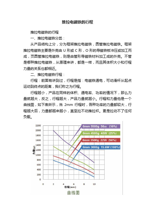
行程越小,产品在同样的体积、通电率、功率的情况下,那么力量就越大,反之,行程越大,产品力量就越小。
行程和力量他是一个曲线图,如下表所示,当2mm 行程时,各种功率的力量都较大,行程越大后,力量都越来越小,直至拉不动推拉杆。
更是拉动不了任何负载。
三、行程最大和行程最小:
现有市场中,行程最小的推拉电磁铁0.5mm,
行程最大的推拉电磁铁,那这个数就没有准了,其实再大都可定制,只是代价问题,我司做过最大行程为500mm。
为定制产品。
四、行程大小和体积的关系,一般其况下,我司自凭经验认为,一般行程大小在电磁
铁主体长度的30%以内,如主体长40mm的电磁铁,行程一般不好超过13mm,超过就没力量了。
以上为做电磁铁十五年的经验之谈,没有一定的科学依据,只是供大家型参考及同行探讨。
电机电磁杆产品说明书

No Code -No motor mountRL 300x -WxxxxQF 511150--SIZE 20253250 mm minimum stroke in 50 mm increments TRAVEL DESIGN NO.5 - MetricSCREW CONFIGURA B A L L S C R E WTIONSIZE 456mm------L E A D S C R E WB A L L SC R E WL E A D S C R E WSIZE 234LEADLEAD mm1.5041.50336RL150 -RL004 -RL150 -RL003 -RL003 -RL006 -564848RL004 -RL008 -RL004 -RL008 -E S PRODUCT S - SlideSERIES G - GantryCLASSIFICATION E - ElectromechanicalG C 2BB TYPE B - Ball Bushing C - TC Bushing 234404056MAX [mm]500600600SIZE 44003300500600900256456-L6-MOTOR CONFIGURATION QF11-Foldbackwith 1:1 ratioQF21-*Foldbackwith 2:1 ratioQL11-Inlinewith 1:1 ratioMOTOR CODEWxxxx -Open architectureP/N codeW0000-Blank motor mountECVA * QF21 not available on sizes 2 and 3.RB005 RB010 RB010 RB016 RB010 RB020 51010161020OPTIONS H4-Cylinder replacement only H11-Without cylinder option CB -Proximity switch ready on both ends BB -Shock pads on extension and retraction L4-Lube fitting in saddle port position 2 and 4L6-Lube fitting in saddle port position 3Q1-Corrosion resistant guide shafts (both ends unplated)BOTH ENDSBOTH ENDSBBQFxxQL11Q1CBL6BOTH SIDESL4L4ORDERING DATAUse this information sheet to assist with slide installation and setup. File with maintenance or machine documentation.IMPORTANT INFORMATIONDO NOT DISCARD!SERIES ESG DESIGN 5 SLIDE INFORMATION MANUALSPECIFICATIONSBALL SCREW SERIES ESG REPEATABILITY1±0.010 mm [±0.0004 in]MAXIMUM BACKLASH 20.18 mm [0.007 in]RATED LIFERefer to Life vs. Thrust Chart FULL TRAVEL TOLERANCE 7+3.5/-0.0 mm [+0.138/-0.000 in]DUTY CYCLE100%OPERATING TEMPERATURE 4 - 65°C [40 - 150°F]LUBRICATION INTERVAL 3Horizontal: 2500 km [100 million in], Vertical: 1500 km [60 million in]SPECIFICATIONSSIZE 456M E C H A N I C SMAXIMUM TRAVELmm [in]500 [19.69]600 [23.62]900 [35.43]DRIVE MECHANISM Ball ScrewSCREW DIAMETERmm 121616SCREW CONFIGURATION -RB005-RB010-RB010-RB016-RB010-RB016SCREW LEADmm/rev 51010161016GUIDE SHAFT DIAMETER mm162025GUIDE SHAFT BEARING TYPE Ball BushingS P E E D 4MAXIMUM SPEED mm/sec [in/sec]500 [19.6]1000 [39.3]1000 [39.3]1600 [63.0]1000 [39.3]1600 [63.0]MAXIMUM RPMrev/min 6000MAXIMUMACCELERATION -QL11mm/sec 2[in/sec 2]19.6 [772]-QFx1mm/sec 2 [in/sec 2]9.8 [386]T H R U S T 4MAXIMUM THRUST N [lbf]1360 [306]680 [153]2430 [546]1520 [342]2430 [546]1520 [342]NOMINAL THRUST 5N [lbf]400 [90]330 [74]1270 [285]975 [219]1270 [285]975 [219]T O R Q U E PERMISSIBLE DRIVE TORQUE 6-QL11Nm [in-lb] 1.2 [10.62] 4.3 [38.06] 4.3 [38.06]-QFx1Nm [in-lb]0.84 [7.43] 3 [26.55] 3 [26.55]NO-LOAD TORQUENm [in-lb]0.15 [1.33]0.40 [3.54]0.60 [5.31]W E I G H TTOTAL @ ZERO STROKE (W OT )kg [lb] 6.21 [13.7]8.56 [18.87]11.19 [24.67]TOTAL LENGTH ADDER (W LT )kg/mm [lb/in]0.010 [0.57]0.132 [0.74]0.0169 [0.92]MOVING @ ZERO STROKE (W OM )kg [lb] 2.45 [5.41] 3.84 [8.47] 4.89 [10.67]MOVING LENGTH ADDER (W LM )kg/mm [lb/in]0.0006 [0.038]0.0010 [0.058]0.0010 [0.058]I N E R T I AACTUATOR @ ZERO STROKE (J O )kg-m 2 [lb-in 2] 3.00 x 10⁻⁶[0.010] 1.50 x 10⁻⁵ [0.051] 1.50 x 10⁻⁵ [0.051]LENGTH ADDER (J L )kg-m 2/mm [lb-in 2/in]9.85 x 10-9 [0.0009] 2.90 x 10⁻⁸ [0.0025]2.90 x 10⁻⁸ [0.0025]MOVING WEIGHT ADDER (J M )kg-m 2/kg [lb-in 2/lb] 6.21 x 10-72.48 x 10-6 2.48 x 10⁻⁶ 6.36 x 10⁻⁶ 2.48 x 10⁻⁶ 6.36 x 10⁻⁶[9.63 x 10⁻⁴][3.85 x 10⁻³][3.85 x 10⁻³][9.86 x 10⁻³][3.85 x 10⁻³][9.86 x 10⁻³]MOTORCONFIGURATION (J Q )-QF11kg-m 2 [lb-in 2] 1.40 x 10⁻⁵ [0.048] 4.71 x 10⁻⁵ [0.161]4.71 x 10⁻⁵ [0.161]-QF21 2.75 x 10⁻⁵ [0.094]8.28 x 10⁻⁵ [0.283]8.28 x 10⁻⁵ [0.283]-QL113.14 x 10-6 [0.011] 6.11 x 10⁻⁶ [0.021]6.11 x 10⁻⁶ [0.021]NOTES:1) UNIDIRECTIONAL2) AXIAL FREE PLAY WHEN DRIVE SHAFT LOCKED3) REFER TO OPERATING INSTRUCTIONS FOR RE-LUBRICATION DETAILS 4) REFER TO PERFORMANCE CHARTS IN CATALOG 5) 2500 km [100 MILLION in] LIFE6) CORRESPONDS TO MAXIMUM THRUST7) FOR HOMING AND INCREASED APPLICATION FLEXIBILITY, INCLUDE EXTRA TRAVEL WHEN NECESSARY 8) ALL DIMENSIONS ARE FOR REFERENCE ONLY UNLESS SPECIFICALLY TOLERANCED. REFER TO ONLINE SIZING SOFTWARE FOR ACTUAL VALUES.SPECIFICATIONSLEAD SCREW SERIES ESG REPEATABILITY 1±0.5 mm [±0.020 in] (Typical)MAXIMUM BACKLASH 20.20 mm [0.008 in]RATED LIFERefer to Online SizingFULL TRAVEL TOLERANCE +3.5/-0.0 mm [+0.138/-0.000 in]MAXIMUM DUTY CYCLE 35%OPERATING TEMPERATURE 4 - 65°C [40 - 150°F]LUBRICATION INTERVAL 3Horizontal: 500 km [20 million in], Vertical: 250 km [10 million in]SPECIFICATIONSSIZE23456M E C H A N I C SMAXIMUM TRAVEL mm [in]300 [11.811]400 [15.70]500 [19.69]600 [23.62]600 [23.62]SCREW DIAMETER mm810121616SCREW CONFIGURATION -RL150-RL004-RL150-RL003-RL003-RL006-RL004-RL008-RL004-RL008SCREW LEADmm/rev 1.541.53364848GUIDE SHAFT DIAMETER mm10 [0.394]12 [0.472]16 [0.630]20 [0.787]25 [0.984]GUIDE SHAFT BEARING TYPE Composite Bushing S P E E D 4MAXIMUM SPEED mm/sec [in/sec]30 [1.2]80 [3.15]30 [1.20]60 [2.40]60 [2.40]120 [4.80]80 [3.15]160 [6.30]80 [3.15]160 [6.30]MAXIMUM RPMrev/min1200MAXIMUM ACCELERATION m/sec 2[in/sec 2]0.3 [11.81]1.0 [39.37]0.3 [11.81] 1.0 [39.37]0.3 [11.81] 1.0 [39.37]0.5 [19.69] 1.0 [39.37]0.5 [19.69] 1.0 [39.37]T H R U S T 4MAXIMUM THRUST N [lbf]300 [67.5]150 [33.7]500 [112]250 [56]800 [180]400 [90]1600 [360]800 [180]1600 [360]800 [180]T O R Q U EPERMISSIBLE DRIVE TORQUE 5-QL11Nm [in-lb]0.5 [4.42]0.7 [6.20] 1.2 [10.62] 4.3 [38.06] 4.3 [38.06]-QFx1Nm [in-lb]0.84 [7.43] 3 [26.55] 3 [26.55]NO-LOAD TORQUENm [in-lb]0.09 [0.80]0.12 [1.00]0.15 [1.33]0.40 [3.54]0.60 [5.31]W E I G H TTOTAL @ ZERO STROKE (W OT )kg [lb] 2.57 [5.66] 3.37 [7.42] 6.13 [13.54]8.45 [18.63]11.08 [24.43]TOTAL LENGTH ADDER (W LT )kg/mm [lb/in]0.003 [0.14]0.004 [0.21]0.010 [0.57]0.0132 [0.74]0.017 [0.92]MOVING @ ZERO STROKE (W OM )kg [lb] 1.07 [2.35] 1.50 [3.31] 2.38 [5.25] 3.73 [8.23] 4.735 [10.43]MOVING LENGTH ADDER (W LM )kg/mm [lb/in]0.0004 [0.021]0.0007 [0.038]0.0007 [0.038]0.0010 [0.058]0.0010 [0.058]I N E R T I AACTUATOR @ ZERO STROKE (J O )kg-m 2[lb-in 2]1.66 x 10⁻⁶[0.006]2.09 x 10⁻⁶[0.007]3.00 x 10⁻⁶[0.010]1.50 x 10⁻⁵[0.051]1.50 x 10⁻⁵ [0.051]LENGTH ADDER (J L ) kg-m 2/mm [lb-in 2/in] 1.59 x 10⁻⁹ [0.00014]4.94 x 10⁻⁹ [0.00043]9.85 x 10⁻⁹ [0.0009] 2.90 x 10⁻⁸ [0.0025] 2.90 x 10⁻⁸ [0.0025]MOVING WEIGHT ADDER (J M )kg-m 2/kg [lb-in 2/lb] 3.8 x 10-81.01 x 10-7 3.8 x 10-87.6 x 10-87.6 x 10⁻⁸ 1.52 x 10⁻⁷ 1.01 x 10-72.03 x 10-7 1.01 x 10⁻⁷ 2.03 x 10⁻⁷[5.89 x 10⁻⁵][1.57 x 10⁻⁴][5.89 x 10⁻⁵][1.18 x 10⁻⁴][1.18 x 10⁻⁴][2.36 x 10⁻⁴][1.57 x 10⁻⁴][3.14 x 10⁻⁴][1.57 x 10⁻⁴][3.14 x 10⁻⁴]MOTORCONFIGURATION (J Q )-QF11kg-m 2 [lb-in 2]2.69 x 10⁻⁵ [0.092] 2.69 x 10⁻⁵ [0.092] 1.40 x 10⁻⁵ [0.048] 4.71 x 10⁻⁵ [0.161] 4.71 x 10⁻⁵ [0.161]-QF21––2.75 x 10⁻⁵ [0.094]8.28 x 10⁻⁵ [0.283]8.28 x 10⁻⁵ [0.283]-QL111.89 x 10-6 [0.006]1.89 x 10⁻⁶ [0.006]3.14 x 10⁻⁶ [0.011]6.11 x 10⁻⁶ [0.021]6.11 x 10⁻⁶ [0.021]NOTES:1) UNIDIRECTIONAL2) VALUES CORRESPOND TO INITIAL (AS SUPPLIED/NEW) CONDITION. DUE TO FRICTIONAL WEAR BACKLASH MAY INCREASE OVER TIME.3) REFER TO OPERATING INSTRUCTIONS FOR RE-LUBRICATION DETAILS 4) REFER TO PERFORMANCE CHARTS IN CATALOG 5) CORRESPONDS TO MAXIMUM THRUSTMOUNTING INFORMATION: SERIES ESG SLIDESSTART-UP PROCEDURE• The ESG Slide should be securely mounted before powering up the electric motor.• Care should be taken to provide adequate space for the slide tool plate to extend.• Make sure that the electric motor and the motor mount kit (inline or fold-back) are securely mounted to the cylinder and fastened with the recommended tightening torques.• The cylinder rod of the ECV is a non-rotating element. When tightening or loosening the threaded joint, use the flats on the rod end to prevent torque transmission into the rod.• DO NOT use the slide in shock or impact load applications (Example: End of travel impact against a fixed stop).• The slide comes with a self aligning rod coupler between the cylinder rod and saddle. This rod coupler prevents internal friction caused by misalignment, provides greater reliability by reducing component wear and simplifying alignment problems.• The maximum input torque and speed should not exceed the values specified in the engineering data on pages 2 and 3.• The slide is designed for use in a clean industrial environment and designed to prevent solid particles from entering the slide.• Do not use the slide in a wash-down environment. Please consult PHD if your application requires wash-down.• The ESG Slide is not field repairable.• After each lubrication interval, inspect shaft couplings, timing belt and screw assembly for excessive backlash. Replace coupling spider or timing belt as necessary.Re-lubricate nut and screw using recommended grease at the following intervalsScrew Type LubricantOrientationHorizontal Vertical -RBxxx (Ball Screw)Castrol Longtime PD2 (NLGI Class 2)100 M in [2500 km]60 M in [1500 km]-RLxxx (Lead Screw)NYE Rheolube 368 AX-120 M in [500 km]10 M in [250 km]PART NO.: 6441-625ESPACE BETWEEN PISTON AND NUTFIGURE CFigure A2RECOMMENDED GREASE: CASTROL LONGTIME PD 2 (NLGI CLASS2)1. Remove the SLOT COVER or LUBE PLUG from the cylinder (Figure A1).• ROTATING (ECVR) UNITS: Fully retract the cylinder and rotate rod clockwise until the LUBE PORT in the piston is accessible. This step may require disengagement of the motor brake or attached load.2. Using grease gun, pump the recommended grease into the LUBE PORT in the BALL NUT (Figure B). Be sure to lubricate the indicated LUBE PORT in the BALL NUT, not extraneous geometry in piston (Figure C).3. Pump the grease until it fully fills the piston assembly.4. Cycle the cylinder at low speeds or by hand keeping any contaminant from entering the tube, then repeat step 3.5. Reinstall the SLOT COVER or LUBE PLUG.RECOMMENDED GREASE: NYE RHEOLUBE 368 AX-11. Remove the SLOT COVER or the LUBE PLUG from the cylinder (Figure A1).• NON-ROTATING (ECVA) UNITS: Fully retract the cylinder and remove the CAP END FHCS in the anti-rotation key. (FIGURE A1)2. ROTATING (ECVR) UNITS: Fully retract the cylinder and rotate the rod clockwise until the LUBE PORT in piston is accessible. (FIGURE A2) Thisstep may require disengagement of the motor brake or attached load.3. Using grease gun, pump the recommended grease into LUBE PORT in the PISTON (Figure A2). Be sure to lubricate the indicated LUBE PORT inthe PISTON.4. Pump the grease until it fully fills the piston assembly.5. For Lead Screw units with 200 mm of travel or more, fully extend the cylinder and lube the screw as shown in (FIGURE B2).6. Cycle the cylinder at low speeds or by hand keeping any contaminant from entering the tube, then repeat step 3.7. Reinstall the SLOT COVER or LUBE PLUG.MAINTENANCE & OPTIONS: SERIES ESG SLIDESSHOCK PADS BOTH DIRECTIONSThis option provides urethane shock pads on retraction and extension for crash protection, eliminating metal-to-metal contact as the saddle reaches physical end of travel. This -BB option does not affect the overall slide length.CYLINDER REPLACEMENT ONLY (WITHOUT SLIDE)H11SLIDE REPLACEMENT ONLY (WITHOUT CYLINDER)500x -511010--4--This option provides complete cylinder replacement motormounting and is included/excluded based on ordering specifications. If motor mounting is desired, full unit description is required.This option provides the slide mechanism only without cylinder or motor mounting. Included with option -H11 is all the hardware required for mounting standard PHD Series ECV Cylinders or pneumatic standard VDMA/ISO cylinders to the slide. A self-aligning rod coupling is also provided, making it easy to attach the appropriate VDMA/ISO cylinder. (No extra rod extension required.)11--NOTES:1) LOCK SCREW TORQUE IS 30 in-lb [3.39 Nm].SIZE B C 2 5.5173 5.59439539639PART NO.: 6441-625EMOTOR CODEYour Motor, Your Way customizable motor mounting is generated by PHD’s extensive motor database at www.config.. The user may select their compatible motor of choice from the pre-populated motor database. In the event the chosen motor is not in the database, they may enter necessary motor features to generate the PHD motor code.The tailored motor mounting components are included with the specified driver and shipped in kit form.Extremely hard corrosion-resistant coating on the guide shafts for use in applications where moisture may corrode untreated hardened and ground shafts. End faces of the shafts remain uncoated. Consult PHD for fully coated shafts.LUBE FITTING IN SADDLE PORT POSITION 2 AND 4Lube fittings provide an easy efficient method for lubricating the bearings and shafts for extended life beyond the normal catalog specifications. Periodic lubrication (every 25 million inches of travel [635 km]) is recommended for applications where heat, dust, orother conditions will dry out the bearings and shafts. PHD suggests a lightweight oil.NOTE: *SEE CATALOG DIMENSIONSLUBE FITTING IN SADDLE PORT POSITION 3CORROSION RESISTANTGUIDE SHAFTSPROXIMITY SWITCH READY BOTH ENDSThis option provides targets in the slide saddle for use with 8 mm inductive proximity switches. The end plates of the slide come standard with provisions for mounting the 8 mm proximity switches on both ends. Proximity switches must be ordered separately.SIZEA B C D 220.53427.57.5314.528329414.52837.59514.528438614.528518ASSEMBLY INSTRUCTIONS(Please use Loctite 248 or equivalent on all fasteners)1.Mount the coupling hub half 5 on the ECV cylinder shaft. Dimensions in Figures D & E are factory suggestions and may not work in every combination. Ensure maximum coupling engagement on each shaft while retaining full spider engagement. Avoid axial loading either shaft.2.Mount the spider 7 to the coupling hub 5.(continued on next page)Figure D Figure E DESCRIPTIONQTY TORQUE in-lb [Nm]SIZE 2SIZE 3SIZE 4SIZE 5SIZE 61Coupling Housing 1----------2Motor Mounting Plate1----------3Brite Zinc Plate Metric Fasteners 426[2.9]26[2.9]50[5.5]50[5.5]50[5.5]4Brite Zinc Plate Metric Fasteners 426[2.9]26[2.9]100[11]100[11]100[11]5Coupling Hub 16[0.72]6[0.72]18[2]18[2]18[2]6Coupling Hub 16[0.72]6[0.72]18[2]18[2]18[2]7Coupling Spider 1----------8Hole Plug 2----------9Motor Screw4See note belowNOTE: The torque on these screws will depend on the screw sizes on your motor.Standard Assembly ESG Size Dimension L in [mm]20.118[3]30.118[3]40.197[5]50.295[7.5]60.295[7.5]Assembly with “F” Type Mount ESG Size Dimension M in [mm]20.197[5]30.197[5]40.276[7]50.374[9.5]60.374[9.5]INLINE MOTOR MOUNTING WITH 1:1 DRIVE RATIO3. Mount the other coupling hub 6 on the spider 7. Loosen the cap screw on coupling hub 6.4. Using the four cap screws 4, fasten the housing 1 to the cylinder. If an “F” type foot mounting bracket option is being used, mount thebracket between the cylinder and the housing 1 as shown in Figure E. Align the cap screw on coupling hub 6 with the hole in the housing 1.5. Mount the motor mounting plate 2 to the housing using the four fasteners 3, and tighten to the recommended torque.6. Insert the motor carefully through the motor mounting plate 2 such that the motor shaft enters the hole in the coupling hub 6. You may haveto apply some force to fully insert the motor shaft in the coupling hub.7. With the motor flush to the motor mounting plate, use the mounting screws 9 to fasten the motor to the mounting plate 2.8. To tighten the cap screw on coupling hub 6, align the head of the cap screw with the hole in the housing 1 as shown in Figure F. If you havelost alignment, realign by either pushing or pulling the cylinder rod or by rotating the motor shaft. Tighten to the recommended torque.9. Plug the two holes on the coupling housing using the plastic plugs 8.Figure F(continued on next page)FOLDBACK MOTOR MOUNTING WITH 1:1 DRIVE RATIO FOLDBACK MOTOR MOUNTING WITH 2:1 DRIVE RATIODESCRIPTIONQTY TORQUE in-lb [Nm]ECV20ECV25ECV32ECV40ECV501Motor Mounting Plate 1----------2Drive Cover1----------3Brite Zinc Metric Fasteners 460[7]60[7]60[7]100[11]100[11]4Brite Zinc DIN 7984 Metric Fastener 4100[11]100[11]100[11]100[11]230[26]5Metric Dowel Pin 2----------6Pulley 1----------7Pulley 1----------8Timing Belt1----------9Metric Socket Set Screw 1----15[1.5]27[3]27[3]10Metric Socket Set Screw 1----See note 1 below11Motor Screw 4----12Motor Adaptor Pulley 1See note 4-13Cylinder Adaptor Pulley144[5]44[5]-NOTE:1) The torque on these screws will depend on the screw sizes on your motor.2) The key shown with the cylinder side pulley will be factory fitted on the cylinder shaft.3) The key shown with the motor side pulley to be used from the customer’s motor.4) The torque on this adaptor will depend on the shaft size of the motor. Ø 5 mm shaft = 44 [5]Ø 6 mm to Ø 6.35 mm shaft = 70 [8] Ø 8 mm shaft = 130 [15]ASSEMBLY INSTRUCTIONSUse Loctite 248 or equivalent on all fasteners (excluding Pulley Adapters).Torque to recommended values.1. Attach Motor Mounting Plate 7 to actuator and secure with supplied Fasteners 4.2. Mount motor [not shown] to Motor plate using supplied Fasteners 11.3. Attach Pulleys 6 and 7 to motor and actuator shafts.SIZES 2 & 3a. Insert Pulley Adapter 12 into Pulley 7 and slide over motor shaft.b. Maintain clearance between Pulley 7 and Motor Mounting Plate 1 as shown in fig H .c. Torque Pulley Adapter 7 to recommended value. Ensure pulley is protected while torqueing.d. Place Timing Belt 8 around Pulley 6.e. Insert Pulley Adapter 13 into Pulley 6.f. Slide Pulley Adapter 13 on actuator shaft while also sliding Timing Belt 8 around Pulley 7 as shown in figure I . Maintain clearance between Pulley 6 and Motor Mounting Plate 1 as shown figure H .g. Torque Pulley Adapter 7 to recommended value.ESG Size Dimension N in [mm]20.041[1.0]30.053[1.3]40.067[1.7]50.047[1.2]60.047[1.2]ASSEMBLY INSTRUCTIONSSIZES 4 - 6a. Slide Pulley 7 over motor shaft while insuring proper placement of key in keyway or Set Screw(s) 10 over flat(s)on motor shaft.b. Maintain clearance between Pulley 7 and Motor Mounting Plate 1 as shown in fig H.c. Torque Set Screw(s) 10 to recommended value. There may be multiple Set Screws 10 in Pulley 7.d. Rotate the actuator shaft so the key faces Pulley 7.e. Place Timing Belt 8 around Pulley 6.f. Slide Pulley 6 over actuator shaft while also sliding Timing Belt 8 around Pulley 7 as shown in figure I. Ensure properplacement of key in keyway.g. H. The hub on Pulley 7 should contact theh.4. Verify Pulley 65. Assemble Dowel Pins6. Place Drive Cover 2NOTE: Drive Cover 2。
中国工业电器公司Midi的RMI.4-5 5A型号电磁闸说明书

Min. applicable load Initial contact resistance
Max. switch. voltage
Max. switch. power
Life Electrical life Mechanical life
100 mA at 5 VDC/12 VAC 50 mΩ (at 1 A 6 VDC) 250 VAC / 30 VDC at 10 A 1250 VA / 150 W at 10 A
Drop-out voltage VAC
6
4.8
1.8
12
9.6
3.6
24
19.2
7.2
48
38.4
14.4
115/120
96.0
36.0
230
176.0
66.0
Coil operating range: see diagram n° 1 pag. 15
At 40°C
Pick-up voltage
VDC
Usually rating (1x10⁵ ops) Max. rating (5x10⁴ ops) Material Current Max. switching current
5 A - 250 VAC 5 A - 250 VAC/30VDC 1/6 HP at 240 VAC 5 A - 250 VAC / 30 VDC 6 A - 250 VAC / 30 VDC Silver alloy
250 V 2.2 KV 2 II
General Data
Nominal coil power Operating time (At nominal voltage) Release time (At nominal voltage) Ambient temperature Vibration resistance
艾顿 Moeller 系列 MSC-D DOL 电机启动器 102739 产品说明书

Eaton 102739Eaton Moeller® series MSC-D DOL starter, 380 V 400 V 415 V: 0.12, 0.18 kW, Ir= 0.4 - 0.63 A, 230 V 50 Hz, 240 V 60 Hz, AC voltageGeneral specificationsEaton Moeller® series MSC-D DOL starter1027394015081025886MSC-D-0,63-M7(230V50HZ)/BBA 154 mm 200 mm 45 mm 0.827 kgCSA File No.: 012528 IEC/EN 60947-4-1CSA-C22.2 No. 14 (on request) UL60947-4-1A UL CSAUL 508 (on request) CECSA Class No.: 3211-04 UL Category Control No.: NKJH UL File No.: E123500 CSA-C22.2 No. 14-10Product NameCatalog Number EANModel CodeProduct Length/Depth Product Height Product Width Product Weight CertificationsShort-circuit releaseTemperature compensated overload protection CLASS 10 AScrew terminalsNo2IP20NEMA OtherDirect starterMounting on Busbar 60 mm10.4 A0.63 AIII36000 V ACAlso motors with efficiency class IE3 Starter with Bi-Metal releaseACFitted with: Functions ClassConnectionConnection to SmartWire-DTCoordination typeDegree of protectionModelMounting methodNumber of auxiliary contacts (normally closed contacts) Number of auxiliary contacts (normally open contacts) Overload release current setting - minOverload release current setting - maxOvervoltage categoryPollution degreeRated impulse withstand voltage (Uimp)Suitable forTypeVoltage typeMax. 2000 m -25 °C55 °C 0.6 A0.63 A0.09 kW0.18 kW230 - 415 V AC15 A, 600 V AC, (UL/CSA)1 A, 250 V DC, (UL/CSA)P300, DC operated (UL/CSA) A600, AC operated (UL/CSA)50000 A 9.8 A 1.2 W, Dual-frequency coil in a cold state and 1.0 x Us, at 50 Hz 230 V230 V0 V0 V0 V0 VAltitudeAmbient operating temperature - min Ambient operating temperature - max Rated operational current (Ie)Rated operational current (Ie) at AC-3, 380 V, 400 V, 415 V Rated operational power at AC-3, 220/230 V, 50 HzRated operational power at AC-3, 380/400 V, 50 HzRated operational voltageSwitching capacity (auxiliary contacts, general use) Switching capacity (auxiliary contacts, pilot duty)Rated conditional short-circuit current (Iq), type 2, 380 V, 400 V, 415 VShort-circuit release (Irm) - max Power consumption, sealing, 50 HzRated control supply voltage (Us) at AC, 50 Hz - min Rated control supply voltage (Us) at AC, 50 Hz - max Rated control supply voltage (Us) at AC, 60 Hz - min Rated control supply voltage (Us) at AC, 60 Hz - max Rated control supply voltage (Us) at DC - minRated control supply voltage (Us) at DC - max5.7 W0 W1.9 W0.63 A1.4 WMeets the product standard's requirements.Meets the product standard's requirements.Meets the product standard's requirements.Meets the product standard's requirements.Meets the product standard's requirements.Does not apply, since the entire switchgear needs to be evaluated.Does not apply, since the entire switchgear needs to be evaluated.Meets the product standard's requirements.Does not apply, since the entire switchgear needs to be evaluated.Meets the product standard's requirements.Does not apply, since the entire switchgear needs to be evaluated.Motor Starters in System xStart - brochureSave time and space thanks to the new link module PKZM0-XDM32ME Simple, flexible and safe! Distribution system for motor-starter combinationsProduct Range Catalog Switching and protecting motorsDA-DC-00004910.pdfDA-DC-00004878.pdfeaton-manual-motor-starters-adapter-msc-d-dol-starter-dimensions.eps eaton-general-ie-ready-dilm-contactor-standards.epsDA-CE-ETN.MSC-D-0,63-M7(230V50HZ)_BBAIL03402015ZIL034014ZUIL034038ZUWIN-WIN with push-in technologyDA-CS-msc_d_bba_bg1DA-CD-msc_d_bba_bg1eaton-manual-motor-starters-device-msc-d-dol-starter-wiring-diagram.epsEquipment heat dissipation, current-dependent PvidHeat dissipation capacity PdissHeat dissipation per pole, current-dependent PvidRated operational current for specified heat dissipation (In) Static heat dissipation, non-current-dependent Pvs10.2.2 Corrosion resistance10.2.3.1 Verification of thermal stability of enclosures10.2.3.2 Verification of resistance of insulating materials to normal heat10.2.3.3 Resist. of insul. mat. to abnormal heat/fire by internal elect. effects10.2.4 Resistance to ultra-violet (UV) radiation10.2.5 Lifting10.2.6 Mechanical impact10.2.7 Inscriptions10.3 Degree of protection of assemblies10.4 Clearances and creepage distances10.5 Protection against electric shock10.6 Incorporation of switching devices and components BrochuresCatalogsDeclarations of conformity DrawingseCAD modelInstallation instructionsInstallation videosmCAD modelWiring diagramsEaton Corporation plc Eaton House30 Pembroke Road Dublin 4, Ireland © 2023 Eaton. All Rights Reserved. Eaton is a registered trademark.All other trademarks areproperty of their respectiveowners./socialmediaDoes not apply, since the entire switchgear needs to be evaluated.Is the panel builder's responsibility.Is the panel builder's responsibility.Is the panel builder's responsibility.Is the panel builder's responsibility.Is the panel builder's responsibility.The panel builder is responsible for the temperature rise calculation. Eaton will provide heat dissipation data for the devices.Is the panel builder's responsibility. The specifications for the switchgear must be observed.Is the panel builder's responsibility. The specifications for the switchgear must be observed.The device meets the requirements, provided the information in the instruction leaflet (IL) is observed.10.7 Internal electrical circuits and connections 10.8 Connections for external conductors 10.9.2 Power-frequency electric strength 10.9.3 Impulse withstand voltage 10.9.4 Testing of enclosures made of insulating material 10.10 Temperature rise10.11 Short-circuit rating10.12 Electromagnetic compatibility10.13 Mechanical function。
恒定磁场-推拉式电磁铁

1
CD段线电流在O点处产生的磁感应强度为:
0 I 0 I B2 a y (cos 90 cos180 ) a y 4r 4a 0 I 1 B3 ax 2a 2 故
2013-8-15
AC半圆线电流在O点处产生的磁感应强度为:
0 I 2 B B1 B2 B3 ( a y ax ) 4a
感应强度, B1 与 dl1 及 a R 垂直,并符合右 手螺旋关系。
dl 2
第四章
为区别场点(x, y, z )与源点(x, y, z ),将上式改写成:
0 B 4 c
2013-8-15
I dl aR R
2
I1
dl1
R
2
I
c1
(4-1-5)
r1
F洛 改变 v 的方向, F 改变 电
2013-8-15
v
的大小。
9
第四章
例1:计算长为2 l 、通有电流I的细直导线外 任意一点处的磁感应强度 B 。 z
解: 由比奥——沙伐定律: 0 I dl aR B 4 c R2
选取坐标系——柱坐标系:将导线 对称地置于 z 轴上。 ∵ 源电流I与 无关,则 B 与 也无关,为简单 起见,选场点为 P( r ,0, z ) 。如图
17
分析:∵ 圆形载流线是由无穷多对小电流 元组成,其中每一对小电流元的 Br 相互抵消,结果只 Bz 分量。
2013-8-15
第四章
0 I B 4
2
(a
0
a d a z
2 2
z )
2
3
- 1、下载文档前请自行甄别文档内容的完整性,平台不提供额外的编辑、内容补充、找答案等附加服务。
- 2、"仅部分预览"的文档,不可在线预览部分如存在完整性等问题,可反馈申请退款(可完整预览的文档不适用该条件!)。
- 3、如文档侵犯您的权益,请联系客服反馈,我们会尽快为您处理(人工客服工作时间:9:00-18:30)。
15N 0.6Arms 60N 2.5Arms
LEM-6
力常数(Force Constant) 电阻 25℃3(Resistance 25°C) 电感 3(Inductance)
24N/Arms 33Ω 12mH
注意:
1)在没有散热片和外加风扇的情况下,连续运行此推力,电缸表面温升不超过 100K。
轴长度 L(mm) (Shaft Length)
1076 1126 1176 1226 1276 1326 1376 1426 1476 1526 1576 1626 1676 1726 1776 1826 1876
可选项
可选项
LEM — 3.6
—
XX
—
XX —
XX
10-1700mm
轴重量(kg) (Shaft Mass)
8) 能够最多保持 40 秒,具体咨询产品供应商。
9) 所有参数都是“线—线”测量。
力—占空比曲线:
长行程推拉电磁铁伸出轴参数:
行程(mm) 轴长度 L(mm) 轴重量(kg)
(Stroke) (Shaft Length) (Shaft Mass)
50
226
0.1
100
276
0.2
150
326
0.2
力驱自动化
LEM 系列长行程推拉电磁铁
选型手册
宁波力驱自动化有限公司版权所有
LEM 长行程推拉电磁铁型号:
型 号
额 定 推 力
最 大 推 力
额 定 电 流
最 大 电 流
伸 出 轴 轴 径
线 圈 外 径
线 圈 长 度
线 圈 质 量
电 缆 孔 间 距
端 部 安 装 螺 孔
(N) (N) (A) (A) d(mm) D(mm) A(mm) (kg) B(mm) (mm)
10N 0.6Arms 40N 2.5Arms
LEM-4
力常数(Force Constant) 电阻 25℃3(Resistance 25°C) 电感 3(Inductance)
16N/Arms 21Ω 8.2mH
注意:
10) 在没有散热片和外加风扇的情况下,连续运行此推力,电缸表面温升不超过 100K。
274 324 374 424 474 524 574 624 674 724 774 824 874 924 974 1024 1074
轴重量(kg) (Shaft Mass)
0.33 0.4 0.47 0.54 0.61 0.68 0.77 0.84 0.91 1 1 1.1 1.2 1.3 1.3 1.4 1.5
11) 能够最多保持 40 秒,具体咨询产品供应商。
12) 所有参数都是“线—线”测量。
力—占空比曲线:
长行程推拉电磁铁伸出轴参数:
行程(mm) 100 150 200 250 300 350 400 450 500 550 600 650 700 750 800 850 900
轴长度 L(mm) 244 294 344 394 444 494 544 594 644 694 744 794 844 894 944 994 1044
LEM-8 20 80
152 0.37
LEM-16 40 160
127 0.95
LEM-24 60 240
172 1.25
2-M10×
1.3 5.2 25 50
19
LEM-32 80 320
217 1.55
12
LEM-57 144 576
397 2.75
额定电流:在没有散热片和强制冷却的情况下,连续运行此电流,电磁铁表面温升不超 过 100K。 最大电流:能够最多保持 40 秒的最大电流。 额定推力:额定电流下的电缸推力。 最大推力:最大电流下的电缸推力。
如何订货:
型号
最大推力
行程
LEM — 2.6
—
XX
10-1700mm
可选项 — XX —
可选项 XX
(空) 标准 FO 只要线圈 SO 只要轴
ST 标准 wp 防水 AC 抗腐蚀
LEM-3.6
电长行程推拉电磁铁线圈参数:
LEN-3.6 电磁铁参数 连续推力 1(Continuous Force) 连续电流 1(Continuous Current) 峰值推力 2(Peak Force) 峰值电流 2(Peak Current)
如何订货:
型号 LEM
最大推力
—4
—
行程 XX
10-1750mm
可选项
可选项
—
XX —
XX
(空) 标准 FO 线圈 SO 只要轴
ST 标准 wp 防水 AC 抗腐蚀
LEM-6
长行程推拉电磁铁线圈参数:
LEM-6 电磁铁参数 连续推力 1(Continuous Force) 连续电流 1(Continuous Current) 峰值推力 2(Peak Force) 峰值电流 2(Peak Current)
2)能够最多保持 40 秒,具体咨询产品供应商。
3)所有参数都是“线—线”测量。
力—占空比曲线:
长行程推拉电磁铁伸出轴参数:
行程(mm) (Stroke)
100 150 200 250 300 350 400 450 500 550 600 650 700 750 800 850 900
轴长度 L(mm) (Shaft Length)
LEM-2.6
长行程推拉电磁铁定子参数:
LEM-2.6 电磁铁参数 连续推力 1(Continuous Force) 连续电流 1(Continuous Current) 峰值推力 2(Peak Force) 峰值电流 2(Peak Current)
6.6N 0.4Arms 26.4N 1.6Arms
6) 所有参数都是“线—线”测量。
力—占空比曲线:
长行程推拉电磁铁伸出轴参数:
行程(mm) (Stroke) 50 100 150 200 250 300 350 400 450 500 550 600 650 700 750 800 850
轴长度 L(mm) (Shaft Length)
202 252 302 352 402 452 502 552 602 652 702 752 802 852 902 952 1002
0.8 0.9 0.9 1 1 1 1.1 1.1 1.2 1.2 1.3 1.3 1.3 1.4 1.4 1.5 1.5
(空) 标准 FO 只要线圈 SO 只要轴
ST 标准 wp 防水 AC 抗腐蚀
LEM-4
长行程推拉电磁铁线圈参数:
LEM-4 电磁铁参数 连续推力 1(Continuous Force) 连续电流 1(Continuous Current) 峰值推力 2(Peak Force) 峰值电流 2(Peak Current)
行程(mm) (Stroke) 900 950 1000 1050 1100 1150 1200 1250 1300 1350 1400 1450 1500 1550 1600 1650 1700
轴长度 L(mm) (Shaft Length)
1028 1078 1128 1178 1228 1278 1328 1378 1428 1478 1528 1578 1628 1678 1728 1778 1828
LEM-2.6
力常数(Force Constant) 电阻 25℃3(Resistance 25°C) 电感 3(Inductance)
17N/Arms 54Ω 18mH
注意:
4) 在没有散热片和外加风扇的情况下,连续运行此推力,电缸表面温升不超过 100K。
5) 能够最多保持 40 秒,具体咨询产品供应商。
200
376
0.3
250
426
0.3
300
476
0.3
350
526
0.4
400
576
0.4
450
626
0.5
500
676
0.5
550
726
0.6
600
776
0.6
650Biblioteka 8260.6700
876
0.7
750
926
0.7
800
976
0.7
850
1026
0.8
如何订货:
型号
最大推力
行程
行程(mm) (Stroke) 900 950 1000 1050 1100 1150 1200 1250 1300 1350 1400 1450 1500 1550 1600 1650 1700
行程(mm) (Stroke) 950 1000 1050 1100 1150 1200 1250 1300 1350 1400 1450 1500 1550 1600 1650 1700 1750
轴长度 L(mm) 1094 1144 1194 1244 1294 1344 1394 1444 1494 1544 1594 1644 1694 1744 1794 1844 1894
轴重量(kg) 1.5 1.6 1.7 1.7 1.8 1.9 2 2 2.1 2.2 2.3 2.3 2.4 2.5 2.6 2.6 2.7
轴长度 L(mm) (Shaft Length)
1052 1102 1152 1202 1252 1302 1352 1402 1452 1502 1552 1602 1652 1702 1752 1802 1852
轴重量(kg) (Shaft Mass)
0.8 0.9 0.9 0.9 1 1 1.1 1.1 1.2 1.2 1.2 1.3 1.3 1.4 1.4 1.4 1.5