
思科9509SAN交换机白皮书
iSCSI
FCIP
Cisco MDS 9509 448
1.44Tbps 10Gbps Cisco MDS 9509 Cisco MDS 9509
Cisco MDS 9509
Cisco MDS 9509 Cisco MDS 9500 Cisco MDS 9509 Cisco MDS 9509 Cisco MDS 9500 Cisco MDS 9509 Cisco MDS 9500
- N_Port WWN - N_Port FC-ID - F_Port - SCSI LUN
FC-SP
RSCN
- SSHv2 - SNMPv3
- FC-PH, Revision 4.3 - FC-PH-2, Revision 7.4 - FC-PH-3, Revision 9.4 - FC-GS-2, Revision 5.3 - FC-GS-3, Revision 7.01 - FC-FLA, Revision 2.7 - FC-FG, Revision 3.5 - FC-SW-2, Revision 5.3 - FC-AL, Revision 4.5 - FC-AL-2, Revision 7.0 - FC-PLDA, Revision 2.1 - FC-VI, Revision 1.61 - FCP, Revision 12 - FCP-2, Revision 7a - FC-SB-2, Revision 2.1 - FC-BB, Revision 4.7 - FC-FS, Revision 1.7 - FC-PI, Revision 13 - FC-MI, Revision 1.99 - FC-Tape, Revision 1.17
Call Home
visor
ISL
Cisco MDS 9509 CLI Cisco Fabric Manager Cisco Fabric Manager
16
ASIC
ISL PortChannel
Cisco MDS 9509 16 2Gbps
FSPF 16
Cisco MDS 9509 MDS 9500
Cisco MDS 9509
Cisco MDS 9509
Cisco MDS 9509 / ACL
Cisco MDS 9509
VSAN
FCC QoS 256 1/2Gbps 768 44Tbps 10Gbps TCO Cisco MDS 9509 1. MDS 9509 Cisco SAN
TCO VSAN
MDS 9000
CLI
Cisco Fabric Manager Java Cisco Fabric Manager
SFP
VSAN
Cisco Fabric Manager
API
/
1/2Gbps 255 16 48 1Gbps 448 16 1/2Gbps 224 1/2Gbps
2Gbps
1-Gbps-SW 1-Gbps-SW 1-Gbps-LW 2-Obps-SW 2-Obps-SW 2-Obps-LW
DS-X9016 DS-X9032 DS-SFP-FC2G-SW DS-SFP-FC2G-LW
Cisco MDS 9000 Cisco MDS 9000 1/2Gbps 1/2Gbps
16 32 -SW -LW
1/2-Gbps FC 1/2-Gbps FC LC LC
SFP/LC SFP/LC
WS-C9509= WS-X9530= WS-9SLOT-FAN= WS -CAC-2500W= WS-CDC-2500W= DS-X9016= DS-X9032= DS-SFP-FC2G-SW= DS-SFP-FC2G-LW=
Cisco
Cisco MDS 9509 99. Cisco MDS 9509 999%
Cisco MDS 9509
Cisco MDS 9500
Cisco MDS 9509
Cisco MDS 9500 9 8 48 1Gbps 16
Cisco MDS 9509 224 1/2GbpsBiblioteka Cisco MDS 9509
MDS 9509 MDS 9500 Supervisor 1 MDS 9500 MDS 9500 MDS 9500 Cisco MDS 9000 Cisco MDS 9000 1/2Gbps 1/2Gbps 2500W AC 2500W DC 16 32 -SW -LW 1/2-Gbps FC 1/2-Gbps FC LC LC SFP/LC SFP/LC
2
6500
2000
17.25
18.8
43.1
46.0cn 21.64
15RU 55.0 19 EIA
RADIUS
AAA
55
2 2500W
25
7 78
CLI
Supervisor/ 70
- CiscoWorks 2000
Supervisor Compact Flash 2500AC
-
100-240VAC 16A 50-60Hz 3Hz
IP RFC 2625 SPAN FC Traceroute FC Ping FC Cisco Fabric Analyzer POST
- 10/100 - RS-232 FC IP
- DB-9 COM
5
- CLI - SNMPv3 IP - 25.5 - SSHv2 - SNMPv3 - Cisco MDS 9000 - Cisco Fabric Analyzer
10%
( )
1300W 2500W
100VAC@16A 200VAC@16A @80A -60VDC
LED SNMP
-48
-60VAC -48
2500W
- 200 lfm1 16 30.5 6 12
- 32 F (0 C)
104 F (40 C) - CE Marking
- -40 F (-40 C)
158 F (70 C)
RH
- UL 60950 - CAN/CSA-C22.2 No. 60950 - EN 60950
RH
- 10%
90%
- IEC 60950 - TS 001
- 5%
95%
6
- AS/NZS 3260 - IEC60825 - EN60825 - 21 CFR 1040
- EN 50082-1 - EN 61000-6-1 - EN 61000-3-2 - EN 61000-3-3
7
(
)
2002
2002© Systems Cisco Systems Cisco Press / Cisco, Cisco IOS, Cisco IOS Cisco Systems Cisco
lit-CH0211CPb-05-23
8
EMC
- FCC Part 15 (CFR 47) Class A - ICES-003 Class A - EN 55022 Class A - CISPR 22 Class A - AS/NZS 3548 Class A - VCCI Class A - EN 55024
EMC
- GR-63-Core NEBS Level 3 - GR-1089-Core NEBS Level 3 - ETS 300 019 Storage Class 1.1 - ETS 300 019 Transportation Class 2.3 - ETS 300 019 Stationary Use Class 3.1 - ETS 300 386
LC SFP LC SFP LC SFP LC SFP LC SFP LC SFP
50/125 62.5/125 9/125 50/125 62.5/125 9/125
500 300 10 300 150 10
4
IETF VSAN
TCP/IP
SNMPv3
RMON MIB
2 3 F E SD F FL TE TL
DS-C9509 DS-X9530 DS-X9530/2 DS-CAC-250OW DS-CAC-2500W/2 DS-CDC-250OW DS-CDC-2500W/2
MDS 9509 MDS 9500 Supervisor 1 MDS 9500 Supervisor 1 MDS 9500 MDS 9500 MDS 9500 MDS 9500 2500W AC 2500W AC 2500W DC 2500W DC
2
Cisco MDS 9509 VSAN
VSAN
Cisco MDS 9509 SAN SAN VSAN SAN VSAN VSAN Cisco MDS 9509 ACL
VSAN
SAN VSAN
Cisco MDS 9509
Cisco MDS 9509
FC Traceroute
Cisco MDS 9509
Cisco MDS 9509
SSH RADIUS SNMPv3
(Role-based Access Control) Cisco MDS 9509 FC-SP
3
Cisco MDS 9509 CLI Cisco IOS CLI Cisco MDS 9000 CLI
Supervisor Supervisor 1+1
Cisco MDS 9509
SAN
1 Cisco MDS 9509
TCO / Cisco MDS 9509
iSCSI
FCIP
Cisco MDS 9509 SNMPv3 LUN
RADIUS
Supervisor Supervisor Supervisor Super-
用于思科以应用为中心的基础设施的Cisco Nexus 9500 平台交换机

产品手册用于思科以应用为中心的基础设施的 Cisco Nexus 9500 平台交换机产品概述不断变化的应用环境向支持这些环境的 IT 基础设施提出了新的需求。
随着应用工作负载部署到包含虚拟化服务器、非虚拟化服务器以及存储基础设施的混合环境中,您便需要一种可为各种裸机、虚拟化和云计算环境提供一致的连接性、安全性和可视性的网络基础设施。
例如:●应用实例采用动态方式创建,因此应用网络连接的调配、修改和删除也需要采取动态方式。
●业务部门需要加速应用部署,IT 部门必须提供共享 IT 基础设施,来解决市场的需求并实现积极的投资回报(ROI)。
●组织部署混合自定义应用、开源应用和现有商业应用时,IT 部门必须针对支持多租户的环境进行安全和服务质量 (QoS) 的管理。
●应用已经过渡到相对不再单一的横向扩展的多节点模式。
支持这种模式的 IT 基础设施必须进行扩展,以便跟上业务发展速度,并且同时要为 1、10、25、40、50 和 100 千兆以太网连接提供支持。
Cisco Nexus® 9000 系列交换机包括模块化和非模块化端口交换机,旨在通过灵活、敏捷、低成本的 Cisco®以应用为中心的基础设施 (Cisco ACI™) 来应对这些挑战。
模块化 Cisco Nexus 9504、9508 和 9516 交换机(图 1)是由无阻塞 100 千兆和 40 千兆以太网线卡、管理引擎、系统控制器和电源支持的 Cisco ACI 主干设备。
图 1.Cisco Nexus 9508 ACI 组件组织可以使用 ACI,以充分发挥基于策略的自动化系统管理办法的优势。
Cisco Nexus 9500 平台的特性和优势Cisco Nexus 9500 平台是一个模块化机箱,在 ACI 模式下支持多达 16 个线卡、2 个管理引擎、2 个机箱控制器、3 个风扇托架、6 个交换矩阵模块和 10 个电源。
该交换机支持 ACI 主干无阻塞 40 千兆和 100 千兆以太网端口上全面的 2 层和 3 层功能(表 1)。
SAN交换机维护操作手册

15 15 -- 2G No_Module (No POD License) Disabled
5)Switchstatusshow
显示交换机运行状态,重点检查如果交换机状态为healthy,则表示交换机当前运行正常,如果有不是healthy的状态出现,则需要根据具体问题使用相关命令继续检查。
10 10 -- 2G No_Module (No POD License) Disabled
11 11 -- 2G No_Module (No POD License) Disabled
12 12 -- 2G No_Module (No POD License) Disabled
13 13 -- 2G No_Module (No POD License) Disabled
5)默认用户:admin,默认密码:password。
2.网络连接登陆
用telnet工具通过IP地址登陆。iP地址默认为10.77.77.77。默认用户:admin,默认密码:password
3.Web方式登录
使用浏览器登录http://10.77.77.77,主机需安装java控件。默认用户:admin,默认密码:password
switchName: SW1
switchType: 34.0
switchState: Online
switchMode: Native
switchRole: Principal
switchDomain: 1
switchId: fffc01
switchWwn: 10:00:00:05:1e:06:d7:04
思科 Nexus 9500 云级线卡和交换矩阵模块 产品手册说明书
产品手册思科 Nexus 9500云级线卡和交换矩阵模块目录产品概述3思科 Nexus 9500 平台云级线卡3思科 Nexus 9500 云级平台交换矩阵模块和性能5支持的光纤模块6机械规格7监管标准合规性8订购信息8保修9服务与支持9 Cisco Capital 10更多信息10产品概述思科 Nexus® 9500 交换平台(图 1)提供三种模块化机箱:●思科 Nexus 9500 4 插槽交换机●思科 Nexus 9500 8 插槽交换机●思科 Nexus 9500 16 插槽交换机图 1.思科 Nexus 9500 系列云级交换机机箱思科 Nexus 9500 系列模块化交换机能够支持最高 172.8 Tbps 的带宽,并可通过全面的云级线卡和交换矩阵模块选择提供 1、10、25、40、50 和 100 千兆以太网接口。
使用这些云级线卡,最多可为思科 Nexus 9500 系列交换机配置1. 576 个 100 千兆以太网端口(或)2. 576 个 40 千兆以太网端口(或)3. 2304 个 25 千兆以太网端口(或)4. 2304 个 1/10 千兆以太网端口思科 Nexus 9500 平台云级线卡思科 Nexus 9500 平台广泛支持针对数据中心部署优化的各种热插拔多速云级线卡和交换矩阵模块。
这些云级线卡和交换矩阵模块使用思科®云级 ASIC 构建,为大型可扩展数据中心提供了理想的基础。
思科云级 ASIC 可提供满足全球最大云级数据中心不断发展的需求所需的增强性能和功能。
这些 ASIC 不仅可支持基础性的第 2/3 层网络功能,还能支持一些增强功能,例如基于策略的交换矩阵架构(ACI 或 VXLAN)、智能缓冲、集成线速安全和通过多速以太网端口进行的实时数据流遥测。
表 1.思科 Nexus 9500 云级线卡N9K-X9732C-EX:100 千兆以太网线卡N9K-X9736C-FX:100 千兆以太网线卡N9K-X9732C-FX:100 千兆以太网线卡N9K-X9736C-EX:100 千兆以太网线卡N9K-X97160YC-EX:1/10/25 千兆以太网接入层以及10/40/100 千兆以太网汇聚层线卡N9K-X9788TC-FX:1/10 千兆以太网 BaseT 接入层以及 40/100 千兆以太网汇聚层线卡表 2.思科 Nexus 9500 云级线卡规格*要使用 5 个交换矩阵模块和 X9736C-FX 线卡实现最大带宽,机箱中的线卡只能为 X9736C-FX 线卡。
思科光纤交换机配置管理使用手册
思科光纤交换机配置管理使用手册9124光纤交换机配置管理使用手册1. 2.初始化信息 ........................................................................... .................................................... 3 交换机基本配置 ........................................................................... ............................................ 4 2.1. 2.2. 2.3. 2.4. 2.5. 2.6. 3.4. 5.配置交换机管理地址 ........................................................................... ........................ 4 LICENSE注册 ........................................................................... .................................. 4 配置VSAN ......................................................................... .......................................... 6 配置ZONESET ...................................................................... ...................................... 6 配置ZONE ......................................................................... .......................................... 7 TRUNKING的配置 ........................................................................... .. (7)标准配置模板 ........................................................................... ................................................ 8 常用检查命令 ........................................................................... ................................................ 9 常用配置命令 ........................................................................... ................................................ 9 5.1. 5.2. 5.3. 5.4. 5.5.5.6. 5.7. 5.8. 5.9. 5.10.删除创建的ZONE ......................................................................... .............................. 9 清除配置 ........................................................................... ............................................ 9 设置配置口超时 ........................................................................... .............................. 10 安装与清除license ...................................................................... ............................... 10 显示指定License ...................................................................... ................................. 10 显示全部Licenses ..................................................................... ................................. 10 显示ID ........................................................................... ............................................ 11 命名交换机 ........................................................................... ...................................... 11 设置管理口 ........................................................................... ...................................... 11 禁止与使能Telnet 与ssh .......................................................................... .. (11)5.11. 下载配置文件 ........................................................................... .................................. 12 5.12. 5.13.保存配置 ........................................................................... ...................................... 12 创建与设置VSAN ......................................................................... (12)5.14. 5.15. 5.16. 5.17. 5.18. 5.19. 5.20. 5.21. 5.22. 5.23.分配VSAN成员 ........................................................................... ......................... 12 删除VSAN ......................................................................... .................................... 13 浏览VSAN设置 ........................................................................... ......................... 13 设置FC端口 ........................................................................... ............................... 14 设置Zone ......................................................................... ...................................... 15 设置ZoneSets ........................................................................................................ 15 激活ZoneSet .......................................................................... ............................... 15 浏览Zone信息 ........................................................................... ........................... 15 恢复管理员口令 ........................................................................... .......................... 18 设置端口速率 ........................................................................... (19)1. 初始化信息在启动交换机后,会有类似如下的信息显示:---- System Admin Account Setup ----Enter the password for "admin": 输入admin管理员密码,系统设为P@ssw0rd Confirm the password for "admin": 再次输入admin管理员密码,P@ssw0rd---- Basic System Configuration Dialog ----This setup utility will guide you through the basic configuration ofthe system. Setup configures only enough connectivity for management of the system.Please register Cisco MDS 9000 Family devices promptly with your supplier. Failure to register may affect response times for initial service calls. MDS devices must be registered to receive entitled support services.Press Enter at anytime to skip a dialog. Use ctrl-c at anytime to skip the remaining dialogs.Would you like to enter the basic configuration dialog (yes/no): no MDS Switchswitch login: admin Password:TAC support: /tacCopyright (c) 2002-2019, Cisco Systems, Inc. All rights reserved. The copyrights to certain works contained herein are owned by other third parties and are used and distributed under license. Some parts of this software arecovered under the GNU Public License. A copy of the license is available at /licenses/gpl.html. switch#然后,可以按照类似以太网交换机配置的方法来配置交换机了。
Cisco Nexus 9500 平台线卡和交换矩阵模块
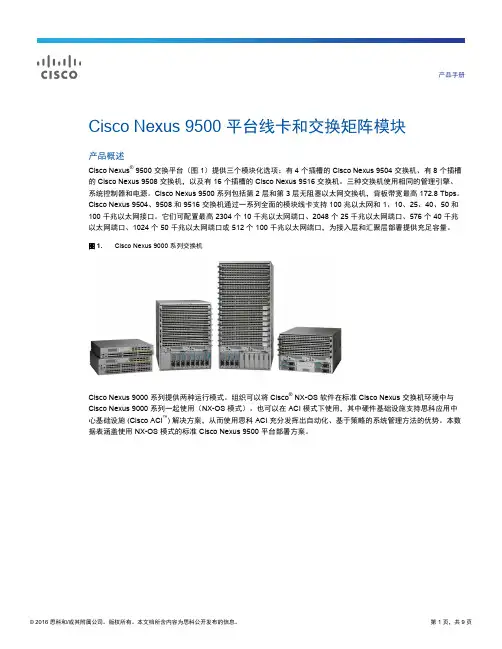
产品手册Cisco Nexus 9500 平台线卡和交换矩阵模块产品概述Cisco Nexus® 9500 交换平台(图 1)提供三个模块化选项:有 4 个插槽的 Cisco Nexus 9504 交换机、有 8 个插槽的 Cisco Nexus 9508 交换机,以及有 16 个插槽的 Cisco Nexus 9516 交换机。
三种交换机使用相同的管理引擎、系统控制器和电源。
Cisco Nexus 9500 系列包括第 2 层和第 3 层无阻塞以太网交换机,背板带宽最高 172.8 Tbps。
Cisco Nexus 9504、9508 和 9516 交换机通过一系列全面的模块线卡支持 100 兆以太网和 1、10、25、40、50 和100 千兆以太网接口。
它们可配置最高 2304 个 10 千兆以太网端口、2048 个 25 千兆以太网端口、576 个 40 千兆以太网端口、1024 个 50 千兆以太网端口或 512 个 100 千兆以太网端口,为接入层和汇聚层部署提供充足容量。
图 1.Cisco Nexus 9000 系列交换机Cisco Nexus 9000 系列提供两种运行模式。
组织可以将 Cisco® NX-OS 软件在标准 Cisco Nexus 交换机环境中与Cisco Nexus 9000 系列一起使用(NX-OS 模式)。
也可以在 ACI 模式下使用,其中硬件基础设施支持思科应用中心基础设施 (Cisco ACI™) 解决方案,从而使用思科 ACI 充分发挥出自动化、基于策略的系统管理方法的优势。
本数据表涵盖使用 NX-OS 模式的标准 Cisco Nexus 9500 平台部署方案。
Cisco Nexus 9500 平台组件Cisco Nexus 9500 平台由图 2 中所示组件以及下面章节中所述组件构成。
图 2.Cisco Nexus 9500 平台组件适用于非 ACI 模式部署的 Cisco Nexus 9500 平台线卡Cisco Nexus 9500 平台支持多种线卡,所有线卡都可以任意组合配置(表 1)。
IBM所有产品详细介绍

为什么选择IBMIBM SAN 产品和解决方案为多协议的局部、校园、城市和全球存储网络提供了整合的中小企业和大型企业 SAN 解决方案。
了解更多信息(英文)我们可以提供:企业级 SAN 导控器针对最高可用性和可扩展性的企业解决方案。
∙IBM System Storage SAN768B and SAN384B∙IBM TotalStorage SAN256B∙Cisco MDS 9513∙Cisco MDS 9509∙Cisco MDS 9506∙Data Center Fabric Manager (DCFM™)中端 SAN 交换机针对可扩展的、经济的中小企业和大型企业解决方案。
∙IBM System Storage SAN80B-4∙IBM System Storage SAN64B-2(英文)∙IBM System Storage SAN40B-4∙IBM System Storage SAN32B-3∙Cisco MDS 9148∙Cisco MDS 9134 (英文)入门级 SAN 交换机针对简单的、经济的中小企业(SMB)解决方案。
∙IBM System Storage SAN24B-4 Express∙Cisco MDS 9124 ExpressIBM Express 型 SAN 交换机经济且易于使用的中小企业(SMB)解决方案。
∙IBM System Storage SAN24B-4∙Cisco MDS 9124 Express多协议路由器∙IBM System Storage SAN06B-R∙Cisco MDS 9222i∙IBM System Storage SAN04B-R支持和服务∙产品支持(英文)∙服务(英文)∙红皮书(英文)∙教育培训(英文)软件和解决方案∙SAN V olume Controller∙开放软件系列(英文)∙SAN 解决方案(英文)资源∙新闻∙网络连接存储∙案例研究∙存储融资∙System x (x86) 服务器∙BladeCenter 刀片服务器∙Cluster 服务器∙Power Systems (System i 服务器, System p 服务器)∙网络解决方案∙System z (mainframe) 服务器∙存储产品存储产品:∙磁盘系统∙磁带系统∙存储区域网络∙网络连接存储∙介质∙软件∙产品排序(A-Z)高端及企业级系统∙DS6000 系列∙DS8000 系列查看所有企业磁盘系统产品∙IBM XIV 存储系统中端及高性能系统∙Storwize V7000∙DS4800∙DS5000查看所有中端及高性能磁盘系统产品∙DS3950∙DS5020 Express∙DCS9900 系列入门级系统- DS3000 系列∙DS3000 系列∙DS3500 系列∙EXP3000查看所有入门级磁盘系统产品N 系列-统一存储设备∙N7000 系列∙N6000 系列∙N5000 系列∙N3000 系列网关∙N7000 系列网关∙N5000 系列网关N 系列软件和解决方案∙N 系列软件∙N 系列解决方案(英文)归档和保留时间∙DR550∙IBM 信息归档∙具有 Snaplock 的 N 系列(英文)支持和服务∙产品支持(英文)∙N 系列支持和服务(英文)∙磁盘服务(英文)∙针对存储产品的远程支持管理器(英文)∙磁盘红皮书(英文)软件和解决方案∙数据移动性(英文)∙开放式软件系列(英文)资源∙资源库(英文)∙新闻∙N 系列资源(英文)∙案例研究∙产品指南(英文)∙存储融资∙DS 系列说明书(英文)∙DS6000/DS8000 白皮书网络产品:∙以太网交换机∙以太网路由器存储产品特惠方案:∙即刻了解创新领先地位:∙企业信息架构解决方案∙存储虚拟化∙存储XIV 创新∙重复数据删除∙数据移动性(英文)∙新产品资讯全面的存储解决方案∙XIV 智能存储系统方案建议书(418KB)∙存储高可用解决方案建议书(511KB)∙企业级存储DS8000 容灾方案建议书(922KB) ∙更多解决方案获取Adobe® Reader®服务器:∙IBM Power 刀片服务器∙IBM Power 710∙IBM Power 720∙IBM Power 730∙IBM Power 740∙IBM Power 750∙IBM Power 770∙IBM Power 780高性能计算服务器:∙IBM Power 755∙IBM Blue Gene/P (英文)∙HPC 服务器和软件 (英文)软件:∙虚拟化 - PowerVM∙AIX∙IBM i∙Linux∙可用性 - PowerHA (英文)∙安全性 (英文)∙能源(英文)∙管理– Systems Director & VMControl (英文)∙IBM 中间件(英文)解决方案:∙云 (英文)∙事务 (英文)∙分析学 (英文)∙更多解决方案 (英文)。
Arista Layer 1 交换机白皮书说明书
5 Questions to ask before buying a Layer 1 switchDespite the apparent similarity of devices on offer to firms deploying or looking to deploy a Layer 1 switch, there are a number of sometimes subtle but important differences between them. All devices generally offer single nanosecond latency, dynamic patching and port replication, however the availability of features such as media conversion, signal regeneration, statistics and telemetry vary widely across the market.Asking the following five questions before buying a layer 1 switch will give you a guide to available features and ensure that you are selecting the right switch for your needs.1. Does the switch perform Ethernet signal regeneration?Typically inserting any device between Ethernet endpoints can have a detrimental effect on the bit error rate of the traffic carried as well as the ability to meet the Ethernet specifications at an electrical level. Multiple media conversions such as connecting a device via an optical transceiver, and patching it to another optical transceiver or direct-attach copper (DAC) cable can degrade the signal significantly. The results may be frequently detected as packet errors on the endpoints or even difficulty with obtaining a stable link.The solution to this is for the Layer 1 switch ports to perform signal regeneration and clock data recovery. Doing so ensuresthat the outgoing Ethernet stream contains precisely the same data as the incoming data but with the signal and embedded clock margins equivalent to that of the originating data. In scenarios where a Layer 1 switch is used to fan out and replicate Ethernet streams without signal regeneration the probability of bit errors goes up with the number of replicated streams. With signal regeneration there is no such problem as each replicated signal margin is equivalent to the original data. Ethernet signal regeneration converts a Layer 1 switch from a device that may degrade data passing through it to one that actually reducesbit errors to receiving endpoints; in particular when endpoints have longer connections between them. Another key benefitof Ethernet signal regeneration is that it allows the use of different types of Ethernet media between two endpoints without compromising signal integrity. For example one end of a connection can be fiber and the other copper. The Layer 1 switch can also be used to convert individual links to DWDM wavelengths allowing many to share a single fiber pair.2. What kind of monitoring/telemetry is provided?Layer 1 switches are devices that operate on Ethernet links at the physical layer and therefore switch data statically based upon pre-configured rules rather than dynamically. Layer 1 switches need have no knowledge of the content of the Ethernet frame.As such most Layer 1 switches provide very few per port statistics and are often not even able to detect bit or frame errors in the Ethernet frames. Parsing the Ethernet frame and generating statistics requires additional logic. Even the lowest latency Ethernet switches typically require double-digit nanoseconds to do so which is why most Layer 1 devices do not offer them. Some vendors do however offer per port Ethernet statistics such as overall packet and byte counts, packet type counts, Ethernet error counts per type of error and frame size bin counts providing detailed visibility into each endpoint’s Ethernet traffic.As with most Layer 2/3 switches the Layer 1 switch counters are cumulative over time so calculating a time series generally requires periodically polling for a snapshot of the port counters then building it manually. If a Layer 1 switch does offer useful Ethernet statistics it is therefore worth also verifying that the Layer 1 switch has integrated telemetry features to perform more advanced analysis, displays, or even alerting based upon interface statistics.3. Which tranceivers and media types are supported?The SFP (1 GbE) and SFP+ (10 GbE) standards allow 1 and 10 GbE to be carried in a multitude of media types. Devices may be connected via types of optical fiber or electrical cables. There are multiple standards for Ethernet over optical fiber via the SFP/ SFP+ interface with the most common being:1000BASE-SX over multi-mode fibre up to 550 m1000BASE-LX/LX10 over single-mode fibre up to 10 km1000BASE-EX over single-mode fibre up to 55 km1000BASE-ZX over single-mode fibre up to 90 km10GBASE-SR over multi-mode fibre up to 400 m10GBASE-LR over single-mode fibre up to 10 km10GBASE-ER over single-mode fibre up to 40 km10GBASE-ZR over single-mode fibre up to 80 km10GBASE-ZR DWDM over single-mode fibre up to 80 kmThe most common electrical SFP/SFP+ interfaces are:1000BASE-T over twisted-pair cables terminated in RJ-45 connectors in lengths up to 100 m10GbE direct-attach copper or twinax cables in lengths up to 15 mA number of SFP+ transceivers support both 1 and 10 GbE modes and can be configured for either. From a Layer 1 switch perspective support for each of the above standards will require that it can recognise the type of transceiver inserted and configure it for the desired class of operation. It also must supply it with adequate power and remove the heat it generates within the SFP/SFP+ cage.In particular LR, ZR and DWDM transceivers require higher power to be supplied and often specialized cooling within the device. Some optical transceivers can provide information on their light levels however the Layer 1 switch specifically needs to know how to query them; this is an extremely useful feature in troubleshooting errors on the link.When twinax cabling is used in lengths greater than 3m, signal integrity can be an issue requiring that switches possess the appropriate logic to compensate for the varying electrical properties of the profusion of cables available on the market . Each has individually varying electrical characteristics that may or not meet the requisite Ethernet Alliance’s standards (there is no IEEE standard for 10GbE over twinax).All Layer 1 switches support at least some of the above SFP/SFP+ transceivers, it is important however to verify that they support the transceivers and media types that you currently require or may require at a future date.When looking to leverage twinax cables, it is definitely worth finding a Layer 1 switch that has signal integrity features, suchas integrated bit error rate testing (BERT) that maximize flexibility in the choice of twinax cables while maintaining the lowest possible bit error rate.4. What management/operations/industry standard protocols does it interact with?There is a profusion of standards available to interact, directly or programmatically with a network device.Examples include:Web-based Graphical User Interface (GUI)Command-line interface (CLI) via secure shell (SSH), Telnet, serial connectionLocal and remote logging via SyslogJSON-RPC APISimple network management protocol (SNMP) v1, v2, v3NETCONFIt is important that those protocols running over the network offer security in the form of an encrypted transport layer such as the Transport Layer Security (TLS) or HTTPS. Integrating with existing authentication databases via protocols such as the Terminal Access Controller Access-Control System (TACACS) or Remote Authentication Dial-In User Service (RADIUS) are also useful features. Devices may offer support for some or all of these protocols.Santa Clara—Corporate Headquarters 5453 Great America Parkway,Santa Clara, CA 95054Phone: +1-408-547-5500Fax: +1-408-538-8920Email:***************Ireland—International Headquarters3130 Atlantic AvenueWestpark Business CampusShannon, Co. ClareIrelandVancouver—R&D Office9200 Glenlyon Pkwy, Unit 300Burnaby, British ColumbiaCanada V5J 5J8San Francisco—R&D and Sales Office 1390Market Street, Suite 800San Francisco, CA 94102India—R&D OfficeGlobal Tech Park, Tower A & B, 11th FloorMarathahalli Outer Ring RoadDevarabeesanahalli Village, Varthur HobliBangalore, India 560103Singapore—APAC Administrative Office9 Temasek Boulevard#29-01, Suntec Tower TwoSingapore 038989Nashua—R&D Office10 Tara BoulevardNashua, NH 03062Copyright © 2019 Arista Networks, Inc. All rights reserved. CloudVision, and EOS are registered trademarks and Arista Networks is a trademark of Arista Networks, Inc. All other company names are trademarks of their respective holders. Information in this document is subject to change without notice. Certain features may not yet be available. Arista Networks, Inc. assumes no responsibility for any errors that may appear in this document. 02/195. What is its latency and how is it measured?In general Layer 1 switches deliver single digit nanosecond levels of pass-through latency. Ethernet traffic can pass through them and optionally be fanned out in as low as 4 nanoseconds. Actually measuring and confirming this latency is not a simple exercise. Where are these latency values measured from; the transceiver cages? Do they include a transceiver? What is the quoted latency number; is it a minimum, mean, median or other value? Across which ports on the device? The two with the lowest latency between them? All of them? Was the result obtained indirectly by statistical averaging or directly via high-precision packet capture?Decision makers are often asked to take these numbers on trust by vendors as testing it for themselves is usually rather difficult mainly due to the aforementioned complexities. There are independent, unbiased specialist entities such as STAC Research who perform these sort of tests. It is certainly worth asking the vendor precisely what the measurement is that they quote and if they have any independent results to back up their numbers.In summary all Layer 1 switches provide basic Layer 1 functionality however there are key features that vary significantly from product to product. These include questions as to the latency and how it is measured, whether it provides Ethernet signal and clock regeneration, what traffic statistics are available, what media types are supported - and can be converted between - as well as what protocols can be used to manage the switch.Ask yourself those questions and you are sure to select the right device for your requirements.。
使用Cisco MDS 9700和MDS 9500多层导向器的大型SAN设计最佳实践
白皮书使用 Cisco MDS 9700 和 MDS 9500 多层导向器的大型 SAN 设计最佳实践概述随着 SAN 的规模不断增长,需要考虑很多因素来帮助扩展和管理它们。
本文档重点介绍数据中心内的大型 SAN 部署,并为您提供设计大型物理交换矩阵时要应用的最佳实践和设计注意事项。
它不适用于实施 VSAN 间路由 (IVR)、基于光纤通道或 IP 光纤通道 (FCIP)的 SAN 扩展或智能交换矩阵应用(例如 Cisco® Data Mobility Manager 或Cisco I/O 加速 [IOA] )的网络。
设计参数在 SAN 环境中,需要解决许多设计标准,例如访问共享存储帧、网络拓扑和交换矩阵扩展的服务器数量。
本文档重点介绍以下设计参数:●包含 2500 个或更多终端设备(服务器、存储和磁带设备)的部署●大多数终端设备具有 8 Gbps 和 16 Gbps 连接速度的部署●使用相同的双物理交换矩阵(交换矩阵 A 和交换矩阵 B)的部署网络注意事项在设计大型 Cisco MDS 交换矩阵时,应该考虑以下注意事项:●端口和端口组●专用和共享速率模式●端口速度●交换机间链路 (ISL)●PortChannel●8 Gbps 和 10 Gbps 光纤通道 ISL 对比●扇入、扇出和超用比●区域类型和智能分区●虚拟 SAN (VSAN)●交换矩阵登录端口和端口组Cisco MDS 9000 系列的每个端口属于一个端口组,该组共享已分配带宽的指定池中的公共资源。
这样,就可以为高带宽和低带宽设备进行适当的带宽分配。
表 1 提供了一些详细信息,以便您更好地了解本白皮书中将会介绍的交换模块端口和端口组的带宽分配。
表 1.光纤通道 (FC) 模块的带宽和端口组配置1安装了交换矩阵 3 模块的 MDS 95132 MDS 9506(全部)和 MDS 9509(全部)或安装了交换矩阵 2 的 MDS 9513 超订用更多3 MDS 9506(全部)、MDS 9509(全部)或 MDS 9513(全部)4 MDS 9700(全部)专用和共享速率模式MDS 9000 系列线卡上的端口被分入不同的端口组,每个端口组的带宽量是固定的(参见表 1)。
思科虚拟设备技术白皮书
White PaperTechnical Overview of Virtual Device ContextsThe Cisco® Nexus 7000 Series Switches introduce support for the Cisco NX-OS Software platform, a new class of operating system designed for data centers. Based on the Cisco MDS 9000 SAN-OS platform, Cisco NX-OS introduces support for virtual device contexts (VDCs), which allows the switches to be virtualized at the device level. Each configured VDC presents itself as a unique device to connected users within the framework of that physical switch. The VDC runs as a separate logical entity within the switch, maintaining its own unique set of running software processes, having its own configuration, and being managed by a separate administrator.This document provides an insight into the support for VDCs on Cisco NX-OS.1. Introduction to Cisco NX-OS and Virtual Device ContextsCisco NX-OS is based on Cisco MDS 9000 SAN-OS and has been developed for data center deployments. It incorporates all of the essential Layer 2 and 3 protocols and other key features found in Cisco IOS® Software. Features such as Cisco In Service Software Upgrades (ISSU), superior fault detection, and isolation mechanisms such as Cisco Generic Online Diagnostics (GOLD) and Embedded Event Manager (EEM) as well as a traditional Cisco IOS Software look and feel for configuration purposes are all included. Cisco NX-OS is based on a modular architecture that supports the independent starting and stopping of processes, and supports multi-threaded processes that run in their own protected memory space.The Cisco Nexus 7000 Series inherits a number of virtualization technologies present in Cisco IOS Software. From a Layer 2 perspective, virtual LANs (VLAN) virtualize bridge domains in the Nexus 7000 chassis. Virtualization support for Layer 3 is supported through the concept of virtual route forwarding instances (VRF). A VRF can be used to virtualize the Layer 3 forwarding and routing tables. The virtualization aspect of the Cisco NX-OS Software platform has been extended to support the notion of virtual device contexts (VDCs). A VDC can be used to virtualize the device itself, presenting the physical switch as multiple logical devices. Within that VDC it can contain its own unique and independent set of VLANs and VRFs. Each VDC can have assigned to it physical ports, thus allowing for the hardware data plane to be virtualized as well. Within each VDC, a separate management domain can manage the VDC itself, thus allowing the management plane itself to also be virtualized.The definition of a switch control plane includes all those software functions that are processed by the switch CPU (found on the central supervisor). The control plane supports a number of crucial software processes such as the routing information base, the running of various Layer 2 and Layer 3 protocols, and more. All of these processes are important to the switches interaction with other network nodes. The control plane is also responsible for programming the data plane that enables many hardware-accelerated features.In its default state, the switch control plane runs a single device context (called VDC 1) within which it will run approximately 80 processes. Some of these processes can have other threads spawned, resulting in as many as 250 processes actively running on the system at a time depending on the services configured. This single device context has a number of layer 2 and 3 services running on top of the infrastructure and kernel components of the OS as shown in the following diagram.Figure 1. Default Operating Mode with Single Default VDCThis collection of processes constitutes what is seen as the control plane for a single physical device (that being with no other virtual device contexts enabled). VDC 1 is always active, always enabled, and can never be deleted. It is important to reiterate that even in this default mode, virtualization support via VRF and VLAN is still applicable within the default VDC (or any VDC). This can also be viewed as virtualization nesting. At the higher level, you have the VDC. Within the VDC, you can have multiple VRFs and VDCs. In future software releases, you could potentially have further nested levels with features like MTR within a VRF.The notion of enabling a subsequent (additional) VDC takes these processes and replicates it for each device context that exists in the switch. When this occurs, duplication of VRF names and VLAN IDs is possible. For example, you could have a VRF called manufacturing in one device context and the same “manufacturing” name applied to a VRF in another virtual device context. Hence, each VDC administrator essentially interfaces with its own set of processes and its own set of VRFs and VLANs, which in turn, represents its own logical (or virtual) switch context. This provides a clear delineation of management contexts and forms the basis for configuration separation and independence between VDCs.Figure 2 depicts the major software elements that enable VDCs. In VDC mode, many benefits can be achieved such as per-VDC fault isolation, per-VDC administration, separation of data traffic,and enhanced security. Hardware resources such as physical interfaces can also be divided between VDCs. Support for hardware partitioning is discussed later in this document.Figure 2. VDC ModeThe use of VDC opens up a number of use cases that can provide added benefits for the administrators of this switch. Use cases for VDCs could include:●Offering a secure network partition between different user departments traffic●Provides empowered departments the ability to administer and maintain their ownconfigurations●One key use for VDC is to provide a device context for testing new configuration orconnectivity options without impacting production systems●Consolidation of multiple departments switch platforms into a single physical platform whilestill offering independence from the OS, administration and traffic perspective●Use of a device context for network administrator and operator training purposes2. VDC ArchitectureThe Cisco NX-OS Software platform provides the base upon which virtual device contexts are supported. The following sections provide more insight into the support for VDCs within this software platform.2.1 VDC Architectural LayersIn analyzing the architectural diagram of the system running in VDC mode (see Figure 2 above), it becomes apparent that not all of the architectural elements of the platform are virtualized. Even though not all layers are virtualized, all of the major components have been built with the purpose to support the concept of VDCs.At the heart of the OS is the kernel and infrastructure layer. The kernel is able to support all processes and all VDCs that run on the switch but only a single instance of the kernel will exist at any one point in time. The infrastructure layer provides an interface between the higher layer processes and the hardware resources of the physical switch (TCAM, etc.). Having a single instance of this layer reduces complexity (when managing the hardware resources). Having a single infrastructure layer also helps scale performance by avoiding duplication of this system’s management process.Working under control of the infrastructure layer is a number of other important system processes, which also exist as a unique entity. Of these, the VDC manager is a key process when it comes to supporting VDCs. The VDC manager is responsible for the creation and deletion of VDCs. More important, it provides VDC-related APIs for other infrastructure components such as the system manager and resource manager to perform their own related functions.When a VDC is created, the system manager is responsible for launching all services required for VDC startup that run on a per-VDC basis. As new services are configured, the system manager will launch the appropriate process. For example, if OSPF were enabled in the VDC named Marketing, then the system manager would launch an OSPF process for that VDC. If a VDC is deleted, then the system manager is responsible for tearing down all related processed for that VDC.The resources manager is responsible for managing the allocation and distribution of resources between VDCs. More about this topic is discussed later in this document, but resources such as VLANs, VRFs, PortChannels, and physical ports are examples of resources that are managed by the resource manager.Sitting above the infrastructure layer and its associated managers are processes that run on a per-VDC basis. Each of these processes runs in its own set of protected memory space. Fault isolation is one of the main benefits derived from the use of a VDC. Should a process fail in one VDC, it will not have an effect on processes running in another VDC.2.2 Virtual Device Context Resource AllocationWhen a VDC is created, selected switch resources can be allocated to that VDC, helping ensure that it has exclusive use of that resource. A resource template controls the allocation of resources and defines how much of that resource can be allocated to a VDC. VDC administrators and users within the VDC cannot change this template. Only the super user is able to change this template. The super user is a user with the highest level of authority to invoke changes to the configuration in the switch. The super user exists within the domain of VDC 1 (the default VDC). Aside from being able to assign physical switch resources between device contexts, the super user has the ability to invoke change in any VDC configuration, create and delete VDCs, and create and delete administrators and users for each VDC. The template is administered separately from the switch configuration, which allows the super user to edit a template without affecting the resource allocation for the VDC that the template has previously been applied to. When the super user wants to apply an updated template to a VDC, that person will have to reapply the template so that it is activated, copied, and merged with the running configuration. For transparent backup purposes, merging templates with the configuration adds the benefit of being able to back up all configurations specific to a VDC by simply backing up the primary configuration. Most, but not all, of the switch resources can be allocated to a VDC. Table 1 lists the resources that can be allocated to VDCs and those that cannot be.Table 1. Switch ResourcesSwitch Resources that Can Be Allocated to a VDC Switch Resources that Cannot Be Allocated to a VDCPhysical Interfaces, PortChannels, Bridge Domains and VLANs, HSRP and GLBP Group IDs, and SPAN CPU*, Memory*, TCAM Resources such as the FIB, QoS, and Security ACLs* Future releases may allow allocation of CPU or memory to a VDC.For many of the resources that can be allocated on a per-VDC basis, it is important to note that the resource is typically managed globally. For example, there are 256 Cisco EtherChannel® link bundles per chassis that can be apportioned across the active VDCs. If those 256 Cisco EtherChannel link bundles are consumed by two VDCs, then there are no more link bundles available for any other VDC in the chassis. Configuring the load balancing option for Cisco EtherChannel is a global configuration and cannot be set on a per-VDC basis. Another example is SPAN. There are two SPAN sessions available for the switch. Both VDC A and VDC B can configure a SPAN session as “monitor session 1”; however, internal to the hardware they are recognized as different SPAN sessions. This is again as a direct result of SPAN being managed as a global resource. As with the link bundle example above, once these two sessions are consumed, there are no more SPAN sessions available for other VDCs.The creation of a VDC builds a logical representation of the Cisco Nexus 7000 Series Switch, albeit initially with no physical interfaces assigned to it. Physical switch ports are resources that cannot be shared between VDCs. By default, all ports on the switch are assigned to the default VDC (VDC 1). When a new VDC is created, the super user is required to assign a set of physical ports from the default VDC to the newly created VDC, providing the new VDC with a means to communicate with other devices on the network. Once a physical port is assigned to a VDC, it is bound exclusively to that VDC, and no other VDC has access to that port. Inter-VDC communication is not facilitated from within the switch. A discrete external connection must be made between ports of different VDCs to allow communication between them.Different port types can be assigned to a VDC. These include Layer 2 ports, Layer 3 ports, Layer 2 trunk ports, and PortChannel (Cisco EtherChannel) ports. Note that the ports on the 32 port 10GI/O Module (N7K-M132XP-12) must be allocated to a VDC in port groupings of four ports. The ports on the 48 port 10/100/1000 I/O Module (N7K-M148GT-11) can be allocated on a per-port basis. Logical interfaces such as SVIs that are associated with the same physical interface cannot be allocated to different VDCs in the current implementation. Thus, it is not possible to virtualize a physical interface and associate the resulting logical interfaces to different VDCs. However, it is possible to virtualize a physical interface and associate the resulting logical interfaces with different VRFs or VLANs. Thus, VDCs can be assigned physical interfaces, while VLANs and VRFs can be assigned logical and physical interfaces.An example of this can be seen in Figure 3. Ports 1 through 8 belong to VDC 5 while ports 41 through 48 belong to VDC 10. Within each VDC, ports are further virtualized belonging to either a VLAN or VRF.Figure 3. VDC VirtualizationAfter a port is allocated to a VDC by the root-admin at default-VDC level, it is up to the VDC-admin to manage (configure and use) the previously assigned port. Running other related commands such as a show interface command, for example, will allow the user to see only those interfaces that have been assigned to the VDC.Each VDC maintains its own configuration file, reflecting the actual configuration of ports under the control of the VDC. In addition, the local configuration will contain any VDC specific configuration elements such as a VDC user role and the command scope allocated to that user. Having a separate configuration file per VDC also provides a level of security that protects this VDC from operation configuration changes that might be made on another VDC.VLANs are another important resource that has been extended in Cisco NX-OS. Up to 16,384 VLANs, defined across multiple VDCs, are supported in a Cisco Nexus 7000 Series Switch. Each VDC supports a maximum of 4096 VLANs as per the IEEE 802.1q standard. The new extended VLAN support will allow an incoming VLAN to be mapped to a per-VDC VLAN. We will refer to this per-VDC VLAN as a bridge domain for clarity. In this manner, a VDC administrator can create VLANs numbered anywhere in the 802.1q VLAN ID range, and the VDC will map that newly created VLAN to one of the default 16,384 bridge domains available in the switch. This will allow VDCs on the same physical switch to reuse VLAN IDs in their configurations, while at the OS level the VLAN is in fact a unique bridge domain within the context of the physical switch. For example, VDC A and VDC B could both create VLAN 100, which in turn could be mapped to bridge domains 250 and 251, respectively. Each administrator would use show commands that reference VLAN 100 to monitor and manage that VLAN.3. Scaling Nexus 7000 Switch Resources Using Virtual Device ContextsEach line card uses a local hardware-forwarding engine to perform Layer 2 and Layer 3 forwarding in hardware. The use of VDCs enables this local forwarding engine to optimize the use of its resources for both Layer 2 and Layer 3 operations. The following section provides more detail on this topic.3.1 Layer 2 Address Learning with Virtual Device ContextsThe forwarding engine on each line card is responsible for Layer 2 address learning and will maintain a local copy of the Layer 2 forwarding table. The MAC address table on each line card supports 128,000 MAC addresses. When a new MAC address is learned by a line card, it will forward a copy of that MAC address to other line cards. This enables the Layer 2 address learning process to be synchronized across line cards.Layer 2 learning is a VDC local process and as such has a direct effect on what addresses are placed into each line card.Figure 4 shows how the distributed Layer 2 learning process is affected by the presence of VDCs. On line card 1, MAC address A is learned from port 1/2. This address is installed in the local Layer 2 forwarding table of line card 1. The MAC address is then forwarded to both line cards 2 and 3. As line card 3 has no ports that belong to VDC 10, it will not install any MAC addresses learnt from that VDC. Line card 2, however, does have a local port in VDC 10, so it will install MAC address A into its local forwarding tables.Figure 4. MAC Address LearningWith this implementation of Layer 2 learning, the Cisco Nexus 7000 Series Switch offers a way to scale the use of the Layer 2 MAC address table more efficiently when VDCs are unique to line cards.3.2 Layer 3 Resources and Virtual Device ContextsThe forwarding engine on each line card supports 128,000 entries in the forwarding information base (used to store forwarding prefixes), 64,000 access control lists, and 512,000 ingress and 512,000 egress NetFlow entries.When the default VDC is the only active VDC, learnt routes and ACLs are loaded into each line card TCAM tables so that each line card has the necessary information local to it to make an informed forwarding decision. This can be seen in Figure 5, where the routes for the default “red” VDC are present in the FIB and ACL TCAMs.Figure 5. Default Resource AllocationWhen physical port resources are split between VDCs, then only the line cards that are associated with that VDC are required to store forwarding information and associated ACLs. In this way, the resources can be scaled beyond the default system limits seen in the preceding example. An example is defined in Table 2.Table 2. Resource Separation ExampleVDC Number of Routes Number of Access Control Entries (ACE) Allocated Line Cards10 100,000 50,000 LC 1, LC 320 10,000 10,000 LC 4, LC 830 70,000 40,000 LC 6In this example, the resources would be allocated as shown in Figure 6.Figure 6. Resource SplitThe effect of allocating a subset of ports to a given VDC results in the FIB and ACL TCAM for the respective line cards being primed with the forwarding information and ACLs for that VDC. This extends the use of those TCAM resources beyond the simple system limit described earlier. In the preceding example, a total of 180,000 forwarding entries have been installed in a switch that, without VDCs, would have a system limit of 128,000 forwarding entries. Likewise, a total of100,000 ACE's have been installed where a single VDC would only allow 64,000 Access Control Entries. More important, FIB and ACL TCAM space on line cards 2, 5, and 7 is free for use by additional VDCs that might be created. This further extends the use of those resources well beyond the defined system limits noted here.As with the TCAMs for FIB and ACLs, the use of the NetFlow TCAM is more granular when multiple VDCs are active. Let us assume the same setup as before, where we have a set of line cards, each of which belong to a different VDC.When a flow is identified, a flow record will be created on the local NetFlow TCAM resident on that line card. Both ingress and egress NetFlow are performed on the ingress line card so it is this ingress line card’s NetFlow TCAM where the flow will be stored. The collection and export of flows is always done on a per-VDC basis. No flow in VDC X will be exported to a collector that is part of VDC Y. Once the flow is created in a NetFlow TCAM on line card X, it will not be replicated to NetFlow TCAMs on other line cards that are part of the same VDC. In this manner, the use of the TCAM is optimized.4. Effect of Virtual Device Contexts on Control Plane ProcessesThe previous sections have highlighted that some system resources have global significance and are managed at the global level while other system resources do not have that global significance and are managed at the VDC level. As with these resources, there are certain control plane processes that, when enabled, have global or per-VDC implications. The following section provides some insight into the main control plane processes that have VDC relevance.4.1 Control Plane Policing (CoPP)The switch control plane controls the operation of the switch, and compromising this entity could affect the operation of the switch. Control plane policing provides a protection mechanism for the control plane by rate limiting the number of packets sent to the control plane for processing.Control plane policing is enabled from the default VDC and runs only in the default VDC. Its application, however, is system wide, and any packet from any VDC directed to the control plane is subject to the control plane policer in place. In other words, there is not any VDC awareness that can be used in the policy to police traffic differently depending on the VDC it came from.4.2 Quality of Service (QoS)Unlike control plane policing, quality of service has configuration implications that have either global or per-VDC significance.Policers, which can be used to provide a rate limiting action on target traffic, are an example of a QoS resource specific to a VDC. Even though the policer is a systemwide resource, once configured it will have relevance only to the ports within that VDC. Any QoS configurations specific to a physical port also have significance only to the VDC that the port belongs to. An example of this type of QoS policy is Weighted RED (WRED), which is used to provide congestion management for port buffers.Classification ACLs used to identify which traffic a QoS policy is going to be applied to are another example of a per-VDC resource. These ACLs are configured within a VDC and applied to ports in that VDC. More important, these QoS ACLs will be installed into the ACL TCAM only on those line cards that have ports in that VDC. In this instance, creating more than one VDC can have a positive effect on scaling TCAM resources beyond what is available for a single VDC.Many of the QoS maps that are used to provide services such as CoS- and DCSP-to-queue mapping and markdown maps for exceed and violate traffic are examples of QoS configuration elements that have global significance. DSCP mutation maps, which offer a way to modify the ingress DSCP value, also have global significance. If these mutation- or CoS-to-queue maps are modified, they will affect packets entering all VDCs.4.3 Embedded Event Manager (EEM)Embedded Event Manager is an event-led subsystem that can automate actions based on a certain event occurring. When an event occurs, such as an OIR event or the generation of a certain syslog message, the system can invoke a user-written script (called an applet) that defines a preset list of actions to invoke.An EEM policy (applet) is configured within the context of a VDC. While most events are seen by each VDC, there are some events that can be seen only from by the default VDC. An example of this event type is those events that are generated by the line cards themselves such as a Cisco GOLD diagnostic run result.EEM maintains a log of EEM events and statistics, and this log is maintained on a per-VDC basis. When a policy is configured, only the VDC administrator can configure and administer that policy. VDC users are not able to administer EEM policies.5. Virtual Device Context Fault IsolationWhen multiple VDCs are created in a physical switch, inherently the architecture of the VDC provides a means to prevent failures within that VDC from affecting other VDCs. So, for instance, a spanning tree recalculation that might be started in one VDC is not going to affect the spanning tree domains of other VDCs in the same physical chassis. An OSPF process crash is another example where the fault is isolated locally to that VDC. Process isolation within a VDC thus plays an important role in fault isolation and serves as a major benefit for organizations that embrace the VDC concept.As can be seen in Figure 7, a fault in a process running in VDC 1 does not affect any of the running processes in the other VDCs. Other equivalent processes will continue to run uninhibited by any problems associated with the faulty running process.Figure 7. Per-VDC Fault IsolationFault isolation is enhanced with the ability to provide per-VDC debug commands. Per-VDC logging of messages via syslog is also another important characteristic of the VDC fault isolation capabilities. When combined, these two features provide a powerful tool for administrators in locate problems.The creation of multiple VDCs also permits configuration isolation. Each VDC has its own unique configuration file that is stored separately in NVRAM. There are a number of resources in each VDC whose associated numbers and IDs can overlap between multiple VDCs without having an effect on another VDCs configuration. For example, the same VRF IDs, PortChannel numbers, VLAN IDs, and management IP address can exist on multiple VDCs. More important, configuration separation in this manner not only secures configurations between VDCs but also isolates a VDC from being affected by an erroneous configuration change in another VDC.6. High Availability and Virtual Device ContextsThe Cisco NX-OS Software platform incorporates a high-availability feature set that helps ensure minimal or no effect on the data plane should the control plane fail. Different high-availability service levels are provided, from service restart to stateful supervisor switchover to ISSU without affecting data traffic.Should a control plane failure occur, the administrator has a set of options that can be configured on a per-VDC basis defining what action will be taken regarding that VDC. There are three actions that can be configured: restart, bringdown, and reset. The restart option will delete the VDC and then re-create it with the running configuration. This configured action will occur regardless of whether there are dual supervisors or a single supervisor present in the chassis. The bringdown option will simply delete the VDC. The reset option will issue a reset for the active supervisor when there is only a single supervisor in the chassis. If dual supervisors are present, the reset option will force a supervisor switchover.The default VDC always has a high-availability option of reset assigned to it. Subsequent VDCs created will have a default value of bringdown assigned to them. This value can be changed under configuration control.Stateful switchover is supported with dual supervisors in the chassis. During the course of normal operation, the primary supervisor will constantly exchange and synchronize its state with the redundant supervisor. There is a software process (watchdog) that is used to monitor the responsiveness of the active (primary) supervisor. Should the primary supervisor fail, a fast switchover is enacted by the system. Failover occurs at both the control plane and data plane layers. At supervisor switchover, the data plane continues to use the Layer 2– and Layer 3–derived forwarding entries simply by maintaining the state written into the hardware. For the control plane,。
CiscoIP城域网技术白皮书
城域网技术概述Cisco Metro IP解决方案正在帮助服务供应商突破传统SONET/SDH 基础架构的限制——利用IP的强大功能,满足新一代节点内(Intra——POP)和交换点(Exchange Point)应用不断增长的带宽和业务需求。
ISP系统——ISP SystemsCisco Metro IP解决方案正在帮助Internet服务供应商突破传统SONET/SDH 基础架构的限制——利用IP的强大功能,满足新一代节点内(Intra——POP)、交换点(Exchange Point)和服务器库/存储应用不断增长的带宽和业务需求。
目前,Cisco 7200/7500和Cisco 12000系列以及Cisco ONS 15194 IP传输集中器均可提供ISP解决方案,适用于622Mbps/2.5Gbps环境。
这些解决方案可随时扩展到10Gbps甚至更高。
地区城域系统——Regional Metro Systems利用OC—48/STM—16和OC——12/STM——4速度的Cisco 12000互联网路由器及动态分组传输(DPT) 技术,Cisco 可提供旨在将互联网和IP的强大功能应用到城域中的地区城域系统。
地区城域解决方案可用于支持IP传输(通过裸光纤、WDM及SONET/SDH)、有线MSO及企业/园区MAN 网络系统。
城域接入系统——Metro Access SystemsCisco 公司通过Cisco 10722系列产品提供独特的Metro IP接入解决方案,帮助服务供应商利用互联网边缘的强大功能、通过直接以太网连接为多住户用户提供城域接入网IP业务,同时为他们提供边缘可编程性。
Cisco 城域IP解决方案的经济性∙概述∙简介∙城域分级体系∙联网方案∙结果∙关于SONET/SDH和RPR/DPT的结论∙结论∙附件A:启用光纤∙附件B:对比RPR与传统SONET/SDH技术∙参考文献概述传统的城域网基础设施在支持IP业务方面效率低下。