晶体生长模拟软件FEMAG-CZ之_Czochralski (CZ) Process (FEMAG-CZ)
晶体生长模拟软件FEMAG之晶体生长各种方法

FEMAGSoft © 2010
VB Growth Method
VB is widely used to grow Si/Ge and compound crystals: (待续)………………
t 1800 1740 1680 1620 1560 1500 1440 1380 1320 1260 1200 1140 1080 1020 960 900 840 780 720 660 600 540 480 420 360 300
2) Part of Germanium crystal grown by CZ method 3) Sappher and lots Compound crystal grown by CZ or its variants, such as Kyropoulos, LEC etc. 4) Market share of CZ wafer in solar market slightly lower than DSS mc wafer
It is assumed that for a certain region of the thermal stresses the crystal is in a metastable state, and a certain perturbation energy is necessary to leave this metastable state. By this model, it can be understood that the crystal can bear higher stresses than the critical values determined by a tensile test. Conforming to the classical idea of dislocation generation it starts somewhere near the growth interface, where the highest stresses are located and then grows deeper into the crystal. At these points of high stress level, the dislocation process may be started due to a perturbation energy resulting from:
晶体生长仿真软件FEMAGCUSP磁场对8英寸半导体级硅晶体生长影响

EFFECT OF A CUSP MAGNETIC FIELD ON OXYGEN CONCENTRATION (continued)
This lower oxygen concentration is the result of: - a different flow configuration: with a cusp field, the main flow cell (also called a Proudman cell) extends farther from the axis and closer to the melt/gas interface, thereby facilitating oxygen evaporation, while without cusp field the main flow cell remains located under the solid/liquid interface The radial segregation is not very different with or without cusp field, showing a strong radial segregation close to the crystal wall in both cases, as a consequence of the strong oxygen evaporation prevailing near the tri-junction
the neutral-axis located on the melt free surface.
SIMULATION PROCESS
The growth process is modeled as Time dependent simulation taking in to account the transient effects taking place during the growth of the crystal
晶体生长计算软件FEMAG系列之晶体生长方法介绍

可扩展性
软件具有开放性和可扩展性, 用户可以根据需要添加新的材 料属性和边界条件。
图形界面
提供友好的图形界面,方便用 户进行模型建立、参数设置和 结果分析。
软件应用领域
半导体晶体生长
用于研究半导体晶体生长过程中的物理和化学行 为,优化晶体质量和性能。
光学晶体生长
用于研究光学晶体的生长过程,优化晶体光学性 能和加工工艺。
增强可视化功能
为了更好地帮助用户理解和分析计算结果,FEMag软件将 增加更强大的可视化功能,如3D图形界面、实时渲染等, 使用户能够更直观地查看和操作计算结果。
拓展应用领域和范围
扩大应用领域
随着晶体生长研究的不断发展,FEMag软件的应用领域将不 断扩大。未来,FEMag软件将不仅应用于传统的晶体生长研 究,还将拓展到其他相关领域,如材料科学、化学、生物学 等。
该软件通过建立数学模型,模拟晶体生长过程中各 种因素对晶体形态、结构和性能的影响。
FEMag软件提供了丰富的材料属性和边界条件设置 ,支持多种晶体结构和生长条件。
软件特点
01
02
03
04
高效计算
采用有限元方法进行数值计算 ,能够快速求解大规模的晶体 生长问题。
精确模拟
能够模拟晶体生长过程中的温 度场、浓度场、应力场等物理 场,以及化学反应过程。
专业和深入。
与实验结果的比较
FEMag与实验的一致性
FEMag软件在模拟晶体生长方面取得了与实验结果高度一致的结果。通过对比实验和模拟数据,可以验证 FEMag软件的准确性和可靠性,进一步推动其在晶体生长研究中的应用。
实验验证的局限性
尽管FEMag软件与实验结果具有较好的一致性,但实验验证仍然存在局限性。实验条件和参数的微小变化可能 会对结果产生显著影响,而模拟结果可能无法完全反映这些细微差异。因此,将实验和模拟结果相结合,进行综 合分析是更为可靠的方法。
FEMAG晶体生长模拟软件之FEMAG-CZ_-_Czochralski_Crystal_Growth_Simulation_by_FEMAGSoft
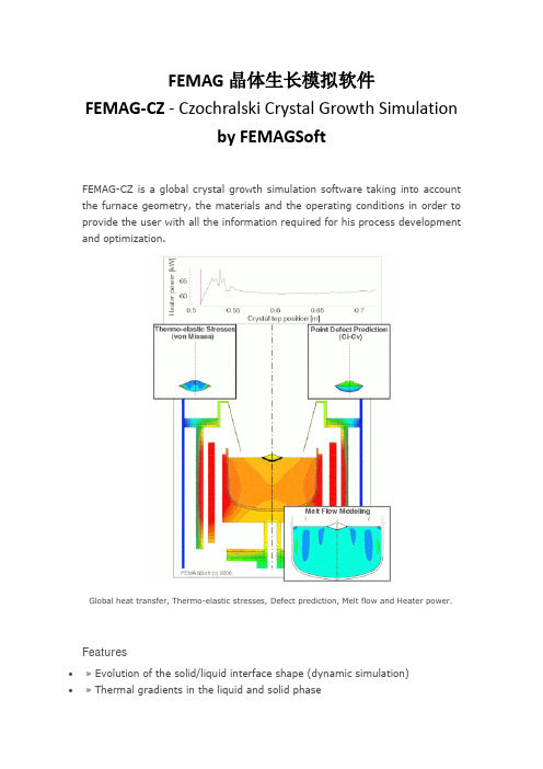
FEMAG晶体生长模拟软件FEMAG-CZ - Czochralski Crystal Growth Simulationby FEMAGSoftFEMAG-CZ is a global crystal growth simulation software taking into account the furnace geometry, the materials and the operating conditions in order to provide the user with all the information required for his process development and optimization.Global heat transfer, Thermo-elastic stresses, Defect prediction, Melt flow and Heater power.Features∙» Evolution of the solid/liquid interface shape (dynamic simulation)∙» Thermal gradients in the liquid and solid phase∙» Heat fluxes in the overall furnace∙» Thermal-stresses in the crystal and hotzone components∙» Continuous feeding∙» Species (dopants and impurities) segregation and concentration∙» Magnetic fieldsSupported Languages:EnglishSupported TechnologiesOperating Systems:LinuxProgramming Languages:C/C++Product Type(s):SoftwareAdditional Product InformationFEMAG family products provide so-called ''global calculations'' , meaning that all the constituents of the furnace are taken into account, together with all heat transfer modes within and between them (conduction, convection and radiation). The modelling of conduction includes the possibility of temperature-dependent and anisotropic conductivity. The modelling of radiative heat exchanges assumes diffuse radiation and can take into account semi-transparent materials through wavelength-dependent radiative properties.The flow in the melt phase can be modelized by a laminar and/or turbulent model. It takes into account natural convection, due to temperature-dependent density and surface tension, and forced convection due to crystal, crucible and/or polycrystal - in case of the FZ process - rotations, possibly under the influence of a magnetic field (axial, cusp, rotating or transverse). Melt flow calculation also considers the effect of gas flow and of tangential forces due to induction (if any) on melt surface.The flow in the gas phase, as a result of an imposed flow rate at gas inlet and of temperature-dependent density, can be modelized by a laminar or a turbulent model.The heating of the process is modelized: ohmic heaters (one or several, coupled or independent) or inductors. In the case of multiple heaters, the user has the possibility to control the heating powers by imposing a specific temperature at given control points.The shapes of interfaces and free-surfaces of the system are calculated. The solidification front and melting front - in case of the FZ process - shapes are calculated taking into account heat dissipation (or absorption) proportional to the growth rate. The melt/gas interface is calculated, as a result of a balance of surface tension, gravity and normal forces due to induction (for the FZ process), providing an accurate meniscus shape.The processes can be modelized by a quasi-steady or by a time-dependent model. The quasi-steady model takes into account the effect of growth rate on heat transfer while assuming a fixed position for all constituents. The time-dependent model considers a geometry that evolves due to crystal lengthening and melt shrinking. It also takes into account the transient effects due to the thermal inertia of all constituents, and due to the inertia of the solidification front shape.Global heat transfer. Temperature isolines are separated by 50 K.。
晶体生长建模软件FEMAG--Numerical Prediction of Bulk Crystal Defects
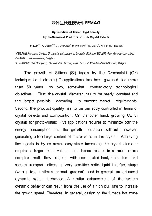
晶体生长建模软件FEMAGOptimization of Silicon I n go t Q ual it yby the Numerical P r e d i c ti on of Bulk Crystal D e f ec t sF. Loix2*, F. D upr e t1,2*, A. de Potter2, R. R ol i n s ky2, W. L i a ng2, N. Van den Boga e rt21CESAME Rese a r ch C e nt e r, Uni v e r s i técatho li que de L ouva i n,Bât i m e nt EULER, 4 av. Georges L e maît r e,B-1348 Louva i n-l a-N e uv e,B e l g i um2FEMAGSoft S.A. Company, 7 Rue André Dumont, Ax i s Parc, B-1435 Mont-Saint-Guibert, B e l g i um The growth of S ili c on(Si) i ngot s by the Czoc hra l s ki (Cz) technique for e l ec t roni c (IC) a ppl i ca t i ons has been governed for more than 50 years by two, somewhat c ont ra di c t ory, t ec hnologi ca l obj ec t i ve s. First, the c rys t a l diameter has to be nearly constant and the l arge s t pos s i bl e according to current market requirements. Second, the product quality has to be pe rfe c t l y c ont rol l e d in terms of c rys t a l defects and composition. On the other hand, grow i ng Cz S i c rys t a l s for photo-volt a i c(PV) a ppl i ca t i ons requires to m i ni m i ze both the energy cons umpt i on and the growth dura t i on without, however, genera t i ng a too l arge content of m i c ro-voi ds in the c rys t a l.A c hi e vi ng these goa l s i s by no means easy s i nc e i nc rea s i ng the c rys t a l diameter re qui re s a l arge r m e l t volume and hence results in a much more complex m e l t flow regime with c om pl i ca t e d heat, momentum and s pec i e s transport effects, a very s ens i t i ve s ol i d-li quid i nt e rfa ce shape (with a l e ss uniform t he rm a l gradient), and in genera l an enhanced dynamic s ys t e m behavior. A s i m il a r enhancement of the system dynam i c behavior can result from the use of a high pull rate to i nc rea s e the growth speed. Therefore, in genera l,de s i gning the furnace hot zonewill require to i ntroduc e appropriate heat s hi e l ds in order to w e ll-cont rol the ra di a t i on hea t transfer whi l e a s a t i s fa c t ory m e l t flow pattern can only be obt a i ne d for l arge diameter c rys t a l s by the ac t i on of transverse or configured m agne t i c fi e l ds.Moreover the s e l ec t i on of opt i m a l proc e ss parameters (heater power, c rys t a l pulling rate, c rys t a l and c ruc i bl e rot a t i on rates, m agne t i c fi e l d i nt ens i ty if any, ambient gas flow rate, etc.) becomes much more difficult in vi e w of the i nc rea s e d system nonl i nea rity and t i m e-depende ncy,e s pec i a ll y during the c rit i ca l process stages (necking, shouldering, t a il-e nd stage, c rys t a l detachment, …).N one t he l e ss,compared to the high difficulty to address these different t ec hnologi ca l i ss ue s,it i s worth observing that huge progress has been achieved in the l a s t decades in s e ve ra l s c i e nt i fi c dom a i ns.F i r s t, the phys i c s of ra di a t i on and c onve c t i on in Cz furnaces, and of defect form a t i on and transport in growing S i c rys t a l s,i s much better known, and hence the m a t he m a t i ca l m ode l s governing Cz S i c ry s t a l growth are better and better e s t a bl i s he d.In spite of the i mport a nt i mprovem e n t s that re m a i n necessary in the m ode li ng of turbulence in the m e l t a nd the ambient gas (i nc l uding the m ode li ng of m e l t turbulence under the effect of a m agne t i c fi e l d) and of the s t ill i ns uffi c i e nt kno w l edge of the m a t e ri a l parameters governing point-and micro-defect e vol ut i on in S i s i ngl e c rys t a l s,an a l m os t complete picture of the phy s i c s of S i growth today i s a va il a bl e.Secondly, num e ri ca l methods and computers have a l s o quickly progre ss e d s i nc e the de ve l opm e n t of the first m ode l s of Cz growth achieved in the 1980’s. Nowadays the qua s i-s t ea dy or t i m e-depende nt s i m ul a t i on of the Cz process hasbecome po ss i bl e in an acce pt a b l e c omput i ng t i m e,with s uffi c i e nt l y refined meshes to resolve the key de t a il s of the problem, and with appropriate num e ri ca l techniques to handle the system de form i ng ge om e try (which comprises s e ve ra l moving components together with free boundaries such as the m e l t-c rys t a l and m e l t-ga s i nt e rfa ce s).Therefore, having at one’s di s posa l the appropriate phys i ca l m ode l s, num e ri ca l tools a nd computer hardware, the route i s directly opened to process opt i m i za t i on by means of num e ri ca l s i m ul a t i on.The obj ec t i ve of the present paper i s to ill us t ra t e how this strategy can be a ppl i e d by use of the FEMAG-CZ software as today co-de ve l ope d by FEMAG Soft S.A. Company and the CESAME research center of the Uni ve rs i téde L ouva i n (Belgium).We will here focus on the S i ingot quality pre di c t i on and i t s opt i m i za t i on.We present a fully t i m e-depende nt m ode l devoted to predict the gl oba l heat transfer in the furnace, the s ol i d-liquid i nt e rfa ce shape, and the re s ult i ng di s tri but i ons of point-and m i c ro-de fe c t s as ca l c ul a t e d from the S i nno-Dornbe rge r (S-D) model together with an e xt ens i on of the l um pe d model of Voronkov and Kulkarni. All the t rans i e nt s are cons i dere d including the effects of c rys t a l a nd c ruc i bl e lift, of the heat capac i t i e s of the furnace cons t i t ue nt s, of the t he rm a l i ne rt i a of the s ol i di fi ca t i on front, and of the dynam i c defect governing l a w s.We hence show that dynamic effects deeply affect the defect di s tri but i on in the c rys t a l(fig 1.). In a ddi t i on to the c l a ss i ca l point-defect e vol ut i on mechanisms, a new l um pe d m ode l i s de ve l ope d to ca l c ul a t e theform a t i on a nd growth of m i c ro-de fe c t s in order to predict their dens i t i e s and s i ze di s tri but i ons anywhere in the c rys t a l.Another key i ss ue in Cz S i growth i s to control the dens i ty of oxygen and any other s pec i e s(i nc l uding dopants and i mpuri t i e s) i ns i de the c rys t a l. M ode li ng i ss ue s will be here aga i n de t a il e d.Finally, off-line process control pri nc i pl e s will be addressed. Results will ill us t ra t e how this tool can he l p in opt i m i z i ng c rys t a l shape and quality.P r e di c t e d defect de l t a C i-C v di s t r i bu t i on (C i, C v be i ng the conc e nt r at i on of i n t e r s t i t i al s , vacanc i e res p e c t i v e l y) with a quas i-s t e ady (a) and a t i me-d e pendent (b)simulation. The OSF ring is located at the position where delta~= 0. This picture highlights the strong impact on the point defect of the transient effects in the growing crystal.。
全球半导体晶体生长建模著名商业软件FEMAG 横向磁场直拉硅晶体生长的全局模拟 优质课件

FEMAGSoft © 2013
Cz Si growth under a TMF (cont’d)
Flow and global heat transfer in a silicon Cz puller
under the effect of a TMF (quasi-steady simulation)
Main modeling hypothesis:
- the viewed and hidden parts are calculated as axisymmetric
- or, equivalently, each surface of the enclosure is viewed as axisymmetric from the other surfaces
dH = L Ha-1 (L = Rs or Rc). Typically dH = 0.05 - 0.08 mm in industrial furnaces.
FEMAGSoft © 2013
Cz Si growth under a TMF (cont’d)
Transverse magnetic fields: FLET method
Bottom: velocity field magnitude and crosssection showing a sharp Hartmann layer along the melt-crucible interface.
FEMAGSoft © 2013
Cz Si growth under a TMF (cont’d)
Hypothesis:
Objective: global, quasi-steady or time-dependent calculations at a reasonable cost
全球半导体晶体生长仿真著名商业软件FEMAG--Numerical Simulation of Bulk Crystal Growth
Introduction (cont’d)
General objective of FEMAGSoft
• FEMAG-2 → FEMAG-3 software generation transition taking place from 2008-2009
→ strongly improved platform in terms of computation time, memory, etc.
FEMAGSoft © 2013
Introduction (cont’d)
Solving these problems requires …
• To develop a sound physical model for each separate effect
→ global and time-dependent modeling of heat transfer, turbulence modeling, defect modeling, …
Analysis of conical growth and shouldering stages m = 8.225 10-4 kg/m.s Wc= 3.82 rpm (0.4 s-1) Ws= -3.82 rpm (-0.4 s-1) Vpul = 1.8 cm/h (5. 10-6 m/s)
FEMAGSoft © 2013
1. Numerical strategy (cont’d)
FEMAG-1 timedependent simulation of Czochralski Ge growth
Direct dynamic simulation (imposed stepwise decrease of heater power, calculated crystal shape): evolution of the temperature field
晶体生长计算软件FEMAG系列之晶体生长方法介绍 ppt课件
16
FEMAGSoft © 2010
定向凝固法(DSS)
在过去几年半导体晶体生长制造商都因采用直拉
法/垂直梯度凝晶体固生长法计(算软件CFZE/MVAGG系F列)之 而获益
晶体生长方法介绍
17
FEMAGSoft © 2010
定向凝固法(DSS)
定向凝固法工艺的主要问题:
增加产出 晶粒尺寸的控制和增大 掺杂/杂质( C/N )分布 位错
晶体生长计算软件FEMAG系列之 晶体生长方法介绍
22
FEMAGSoft © 2010
晶体生长计算软件FEMAG系列之晶 体生长方法介绍
1
晶体生长计算软件FEMAG 之
晶体生长方法介绍
晶体生长计算软件FEMAG系列之
2
晶体生长方法介绍
精品资料
• 你怎么称呼老师? • 如果老师最后没有总结一节课的重点的难点,你
是否会认为老师的教学方法需要改进? • 你所经历的课堂,是讲座式还是讨论式? • 教师的教鞭 • “不怕太阳晒,也不怕那风雨狂,只怕先生骂我
6
FEMAGSoft © 2010
ห้องสมุดไป่ตู้
String Ribbon法 (Evergreen Solar Inc.专利设计)
硅晶体生长方法
导模法(EFG)
晶体生长计算软件FEMAG系列之 晶体生长方法介绍
7
FEMAGSoft © 2010
热场设计的重要性
晶体生长的首要问题是设计适合的热场和 相应的操作条件,这不仅决定了晶体的主 要特性,对于每个集成电路晶片制造商而 言,也是最主要的核心技术所在。
FEMAGSoft © 2010
定向凝固法的热点问题
晶体生长计算软件FEMAG系列之 晶体生长方法介绍
晶体生长模拟软件FEMAG-CZ之-Czochralski-(CZ)-Process-(FEMAG-
晶体生长模拟软件FEMAG-CZ Czochralski (CZ) Process(FEMAG-CZ)FEMAG直拉法模拟软件(FEMAG-CZ)用于模拟直拉法工艺(包括Cz, MCz, VCz,泡生法)。
FEMAG-CZ直拉法模拟软件用于新的热场设计,并研发新的方法以满足新的商业需求点,比如:✓大直径晶锭生长✓无缺陷硅晶锭生长✓提高成品率✓氧含量控制✓降低碳含量✓晶锭半径和沿轴向的电阻率差异减小✓CCZ工艺仿真✓磁场设计✓蓝宝石生长工艺设计FEMAG-CZ模拟软件通过降低试验成本而节省了R&D消耗。
大直径晶锭生长以期不进行大量昂贵的可行性试验生长大尺寸晶体看起来是不太现实的。
FEMAG-CZ软件提供这种可能性。
为了生产450 mm及以上的大尺寸无缺陷硅晶体,晶体生长工程师通过使用FEMAG-CZ来定义关键的工艺参数,而无需任何材料和能源的消耗。
FEMAG-CZ能够设计新的热场并研发新的工艺技术,在FEMAG直拉法模拟软件的帮助下,晶体生长工程师能够在一个有效的虚拟环境中优化每一个关键参数,比如旋转速率,提拉速度,气体流速,压强和功率消耗等。
FEMAG直拉法模拟还能进一步为晶体生长工程师给出在某一工艺配置下产出的最终成品的质量和成本信息,比如晶体中的温度梯度,氧/碳/掺杂物/微缺陷分布等。
通过软件能够获得硅/锗/蓝宝石晶体质量和产品成本信息,这一模拟过程无需任何材料和能量的消耗。
FEMAG 3D 熔体流动模拟结果FEMAG动态模拟无缺陷硅晶锭生长无缺陷晶体硅生长是世界上最大的难点之一。
FEMAG模拟软件能够帮助工程师运用自己创新的技术生长出无缺陷晶体。
运用FEMAG软件缺陷工程模块可以预测晶体炉或者其他指定直拉法工艺环境中生长的晶体成品质量。
缺陷工程模块能够洞悉硅、锗生长过程中填隙原子,空位和微孔演变过程。
FEMAG-CZ能够成为你的测试平台,试验在不同的操作条件下对晶体生长质量的影响,如✓热场设计✓加热器功率✓晶体和坩埚的旋转速率✓晶体提拉速度,坩埚的位置✓气体流率和压强一旦掌握了晶体生长工艺中的动态规律,就可以找到最优的配置以增加成品率和投资回报。
全球半导体晶体生长仿真著名商业软件FEMAG用户故事(一)莱布尼茨晶体生长研究所(IKZ)
全球半导体晶体生长仿真著名商业软件FEMAG用户故事(一)莱布尼茨晶体生长研究所(IKZ)利用FEMAG软件改进区域熔炼法生长锗单晶的工艺区域熔炼法,又称区域提纯,主要用以提纯金属、半导体。
基本过程是将材料制成细棒,用高频感应加热,使一小段固体熔融成液态。
熔融区慢慢从放置材料的一端向另一端移动。
在熔融区的末端,固体重结晶,而含杂质部分因比纯质的熔点略低,较难凝固,便富集于前端。
与常见的直拉法相比,用区熔法生产锗单晶有如下优点:(1)区熔法本身就有提纯功能,因此,区熔法生产锗单晶的产品的纯度高,质量好。
(2)区熔法生产锗单晶不与石英玻璃等容器接触,因此没有沾污。
区熔法生产锗单晶具有上述优点,因此,很多高质量的电子器件,尤其是要求高的集成电路多采用区熔法生产的锗单晶来制造。
但是与此同时,区熔法也有如下缺点:(1)工艺烦琐,生产成本较高。
(2)很难生产出大直径的锗单晶棒。
为了改进区熔法的生产工艺,生产出大直径的锗单晶棒,坩埚的自由悬浮区需要更加稳定的机械平衡与热平衡。
在此过程中,一个光滑的进给杆以及可调的熔化区对于整个相界面形成是必要的。
莱布尼茨晶体生长研究所(IKZ)利用FEMAG-FZ软件进行了此过程的模拟,如下图所示:计算25毫米晶体的温度场:左图为较小的进给杆;中间为开始优化配置;右图为三相点向下移动1毫米依据数值模拟与实验结果的结合,IKZ在原有的工艺基础上进行改进,调整了进给杆的速度,从而优化了晶体的生长速度,如下为35毫米锗晶体轴向纵切后的结构腐蚀图:莱布尼茨晶体生长研究所(Leibniz Institute for Crystal Growth)(IKZ)致力于研究晶体材料生长的基础研究以及相关的生长过程的加工工艺。
其主要研究内容为:•晶体尺寸从分米到纳米之间的材料生长工艺研究•研究并发展新的加工技术•表征晶体以及开发新的表征晶体方法•组件的设计以及相关加工设备的生产。
- 1、下载文档前请自行甄别文档内容的完整性,平台不提供额外的编辑、内容补充、找答案等附加服务。
- 2、"仅部分预览"的文档,不可在线预览部分如存在完整性等问题,可反馈申请退款(可完整预览的文档不适用该条件!)。
- 3、如文档侵犯您的权益,请联系客服反馈,我们会尽快为您处理(人工客服工作时间:9:00-18:30)。
晶体生长模拟软件FEMAG-CZ Czochralski (CZ) Process(FEMAG-CZ)FEMAG直拉法模拟软件(FEMAG-CZ)用于模拟直拉法工艺(包括Cz, MCz, VCz,泡生法)。
FEMAG-CZ直拉法模拟软件用于新的热场设计,并研发新的方法以满足新的商业需求点,比如:
✓大直径晶锭生长
✓无缺陷硅晶锭生长
✓提高成品率
✓氧含量控制
✓降低碳含量
✓晶锭半径和沿轴向的电阻率差异减小
✓CCZ工艺仿真
✓磁场设计
✓蓝宝石生长工艺设计
FEMAG-CZ模拟软件通过降低试验成本而节省了R&D消耗。
大直径晶锭生长
以期不进行大量昂贵的可行性试验生长大尺寸晶体看起来是不太现实的。
FEMAG-CZ软件提供这种可能性。
为了生产450 mm及以上的大尺寸无缺陷硅晶体,晶体生长工程师通过使用FEMAG-CZ来定义关键的工艺参数,而无需任何材料和能源的消耗。
FEMAG-CZ能够设计新的热场并研发新的工艺技术,在FEMAG直拉法模拟软件的帮助下,晶体生长工程师能够在一个有效的虚拟环境中优化每一个关键参数,比如旋转速率,提拉速度,气体流速,压强和功率消耗等。
FEMAG直拉法模拟还能进一步为晶体生长工程师给出在某一工艺配置下产出的最终成品的质量和成本信息,比如晶体中的温度梯度,氧/碳/掺杂物/微缺陷分布等。
通过软件能够获得硅/锗/蓝宝石晶体质量和产品成本信息,这一模拟过程无需任何材料和能量的消耗。
FEMAG 3D 熔体流动模拟结果FEMAG动态模拟
无缺陷硅晶锭生长
无缺陷晶体硅生长是世界上最大的难点之一。
FEMAG模拟软件能够帮助工程师运用自己创新的技术生长出无缺陷晶体。
运用FEMAG软件缺陷工程模块可以预测晶体炉或者其他指定直拉法工艺环境中生长的晶体成品质量。
缺陷工程模块能够洞悉硅、锗生长过程中填隙原子,空位和微孔演变过程。
FEMAG-CZ能够成为你的测试平台,试验在不同的操作条件下对晶体生长质量的影响,如
✓热场设计
✓加热器功率
✓晶体和坩埚的旋转速率
✓晶体提拉速度,坩埚的位置
✓气体流率和压强
一旦掌握了晶体生长工艺中的动态规律,就可以找到最优的配置以增加成品率和投资回报。
直拉法晶体生长中的填隙原子和空位的动态预测
直拉法晶体硅生长中的OSF(氧化诱生层错)预测
提高成品率
在没有任何结构损失的情况下直拉法晶体炉所能达到的最大提拉速度是什么?你是否也在寻找这一难题的解决方案呢?
你知道影响产出的限制因素是什么吗?
FEMAG直拉法模拟软件可以帮助工程师在晶体生长过程的每一个时刻追踪关键参数的变化。
直拉法模拟软件为工程师们提供了在晶体生长过程中凝固前沿形状,热弹性应力,溶体流动形态,气体流动形态,石墨系统的温度变化等信息。
用户可以通过上述的参数信息优化其工艺条件,从而增加凝固生产效率和产出。
因此,借助FEMAG直拉法模拟软件工程师不仅可以增加其产出,还能获取下一代晶体生长工艺技术创新的关键信息。
直拉法晶体生长的三维应力分布
氧含量控制
氧气是晶体生长过程中至关重要的影响因素。
从缩颈阶段到最后的收尾阶段,沿径向和轴向氧含量的控制都是工业上的一大挑战。
N型硅太阳能电池,要求氧含量必须尽可能少,对于IC晶圆而言也必须对氧含量控制得很好。
针对这两类应用,FEMAG直拉法模拟软件能根据其工艺配置(热场配置和操作条件)计算出晶体中的氧气分布。
FEMAG的使用者运用了FEMAG 直拉法横向磁场模块(FEMAGCZ-TMF)来测试新的技术(比如新的磁场设置)来优化氧气的分布情况。
FEMAG直拉法模拟软件为工程师提供了创新的氧气模型以精确地预测晶体中氧气的变化情况。
硅晶体直拉法生长的氧含量预测
碳含量控制
碳是不需要的额外成分,会从石墨元素中渗入到硅晶体中。
晶体中碳含量的增加会对电池转换效率和整个晶圆生产工艺产生阻碍。
碳含量预测涉及几个方面的问题-需要探究原料,晶体生长区中杂质浸入以及密闭性对最终结晶质量的影响。
无论是半导体晶圆或太阳能晶片,碳的存在都会产生负面效应。
FEMAG直拉法模拟软件为工程师们提供了特有的模型去分析指定工艺过程的碳浓度。
FEMAG直拉法模拟软件能够根据其工艺配置(热场配置和操作条件)来计算晶体中的碳分布。
电阻率差异减小
生长轴向和径向电阻率均匀的晶体一直是一大难题,怎样去突破它呢?
高电阻率或者超高电阻率硅晶圆的主要特征是在晶圆厚度方向电阻率的良好均匀性,同时沿轴向和径向的电阻率梯度也具有一定均匀性,且在整个器件加工时都具备稳定性。
这些特征依赖于晶体生长环境,同时也受到硅晶体生长过程中掺杂数量和掺杂类型的影响。
FEMAG-CZ模拟软件通过计算整个晶体生长过程里的掺杂分布来帮助工程师们设计一种理想的晶体生长工艺以达到均匀的电阻率。
一些最早使用FEMAG直拉法模拟软件的企业如今业已成为全球半导体行业中的领军者。
直拉法硅晶体生长的硼浓度分布预测
连续提拉法(CCZ)工艺仿真
连续提拉法晶体生长是一项复杂而具有市场潜力的技术。
显然这项技术相当费钱甚至还会导致企业破产。
但我们仍想知道怎样才能掌握这项工艺?
工业使用者梦想通过CCZ晶体生长法得到超高电阻率硅片。
高电阻率或者超高电阻率硅晶圆,在晶圆厚度方向电阻率的良好均匀性,同时沿轴向和径向的电阻率梯度也具有一定均匀性,且在整个器件加工时具备稳定性。
在晶体生长技术推向工业生产之前都会进行无数次的设计测试和实验,为此需要付出极大的金钱消耗。
利用FEMAG直拉法模拟软件,为获得同一个信息点所需要耗费的成本连实验的十分之一都不到。
FEMAG直拉法模拟软件会帮助晶体生长工程师了解他们的连续提拉法工艺质量和成本来源。
根据指定的工艺条件,掺杂数量和掺杂种类计算掺杂的分布情况,FEMAG 直拉法模拟软件能够帮助工程师设计出能够达到最佳电阻率均匀性的工艺过程。
FEMAG直拉法模拟软件是成功掌握CCZ生长过程的有效途径。
连续提拉法的温度预测
连续提拉法熔体自由表面上部的氩气流场分布
磁场设计
为生长出高质量的晶体,直拉法晶体炉中的磁场设计是很值得去探究的。
但是你知道设计何种在半导体晶锭的工业生产中,会应用各种各样的磁场设计方案,如轴向,cusp型,旋转和横向磁使用者借助FEMAG直拉法模拟软件包括附加的FEMAG-CZ横向磁场软件(FEMAGCZ- TMF)直拉法横向磁场模拟软件是一项首创的三维有限元分析技术,能够在短短一天之内完成工业化学习与掌握成功工艺的关键驱动因素,我们既可以通过实验也可以借助模拟软件来实现,显然发,而通过FEMAG直拉法横向磁场模拟软件所耗费的各种成本要远低于实验的十分之一,提
在横向磁场作用下的三维熔体流动
在横向磁场作用下的三维等温线分布
LED晶体生长过程设计
FEMAG软件支持LED晶体直拉法和泡生法生长模拟。