5 1-2 MWB 桥塞使用说明书
T414CH可取式桥塞资料

LH卡瓦可取式封堵桥塞简介LH可取式封堵桥塞,为液压坐封、上提直接解封式可取桥塞。
桥塞的整体双向卡瓦可以承受双向压力。
该桥塞适合多层封堵的井下封堵,尤其是适合大斜度井和水平井的多层封堵作业。
该桥塞通过油管下入, 液压坐封并丢手。
油管下入打捞。
结构特点z可靠的双向卡瓦z安全的防卡设计z独特的锁定机构z可靠的解封机构z较好的可钻性能LH-A 型 LH-B型安全特性z不怕中途遇阻,防中途坐封;z下入或打捞过程,根据需要可随时洗井;z打捞时,也可正旋管柱,再次脱开桥塞技术参数桥塞型号 套管尺寸 桥塞外径 桥塞长度正向压差 温度LH-55-N80 5-1/2”(124.24mm)114 mm 600 mm 80 Mpa 70ºCLH-55-N75 5-1/2”(124.24mm)114 mm 620 mm 75Mpa 90ºCLH-55-N70 5-1/2”(124.24mm)114 mm 620 mm 70 Mpa 120ºCLH-55-N68 5-1/2”(124.24mm)114 mm 620mm 68 Mpa 150ºCLH-55-H70-1505-1/2”(124.24mm)114 mm 620mm 70Mpa 150ºCLH-55-H70-1755-1/2”(124.24mm)114 mm 620mm 70 Mpa 175ºCLH-70-N75 7” 142-148 mm772 75 Mpa 90ºC LH-70-N70 7” 142-148mm77270Mpa120ºC LH-70-N65 7” 142 -148 mm772 65 Mpa 150ºC卡瓦可取式挤注桥塞简介LN可取式挤注桥塞,为液压坐封、上提直接解封式可取桥塞。
桥塞的整体双向卡瓦可以承受双向压力。
该桥塞适合于挤注水泥,尤其是适合大斜度井和水平井的挤水泥作业。
桥塞介绍演示教学

桥塞桥塞的作用是油气井封层,具有施工工序少、周期短、卡封位置准确的特点,分为永久式桥塞和可取式桥塞两种。
目录)永久式桥塞封层工1简2工作原理3桥塞封层工4该桥塞具有以下特点5主要技术指标6施工方式7施工步骤8注意事项)可取式桥塞封层工1简2工作原理3结构与特点4该桥塞具有以下特点5主要技术指标6适用井条件7施工方式8施工步骤9注意事项10可取式桥塞的打展)永久式桥塞封层工1简2工作原理3桥塞封层工4该桥塞具有以下特点5.主要技术指标:6.施工方式:7.施工步骤:8.注意事项:)可取式桥塞封层工艺2(.简介1.工作原理:2.3结构与特点 4该桥塞具有以下特点 5主要技术指标 6适用井条件 7施工方式8施工步骤9注意事项10可取式桥塞的打展桥塞-桥塞封层工艺(1)永久式桥塞封层工艺编辑本段简述永久式桥塞形成于80年代初期,由于它施工工序少、周期短、卡封位桥塞-桥塞封层工艺置准确,所以一经问世就在油气井封层方面得到了广泛应用,基本上取代了以前打水泥塞封层的工艺技术,成为试油井封堵已试层,进行上返试油的主要封层工艺。
.目前在中浅层试油施工中出现的干层、水层、气层及异常高压等特殊层位,为方便后续试油,封堵废弃层位,通常采用该类桥塞进行封层,同时对于部分短期无开发计划的试油结束井也采用永久式桥塞封井。
此外,该桥塞也用于深层气井的已试层封堵,为上返测试、压裂改造等工艺技术的成功实施提供保障。
工作原理:利用电缆或管柱将其输送到井筒预定位置,通过火药爆破、液压坐封或者机械坐封工具产生的压力作用于上卡瓦,拉力作用于张力棒,通过上下锥体对密封胶筒施以上压下拉两个力,当拉力达到一定值时,张力棒断裂,坐封工具与桥塞脱离。
此时桥塞中心管上的锁紧装置发挥效能,上下卡瓦破碎并镶嵌在套管内壁上,胶筒膨胀并密封,完成坐封。
结构与特点:永久式桥塞外观图见图1,结构有如图2所示几个部分组成:桥塞封层工艺1-销钉;2-锁环;3-上压外套;4卡瓦;5上坐封剪钉;6-保护伞;7-桥塞-桥塞封层工艺封隔件;8-中心管;9-锥体;10-下坐封剪钉该桥塞具有以下特点:①结构简单,下放速度快,可用于电缆、机械或者液压坐封。
油管钻磨桥塞作业指导书

水平井油管输送钻磨桥塞作业指导书1施工准备1。
1 立井架1.1。
1压裂结束后,井口预留18-70×130-70型转换法兰和一个KYS130/70型采油树闸门,拆除其余压裂井口、射孔操作平台和无关的压裂地面流程.1。
1。
2立、校井架:按照设计给定井架型号准备井架,按照试油作业指导书立、校井架,以上工作建议在放喷前、中期进行。
1.2安装井口当自喷日产量低于100m3/d,且井口压力低于0.2MPa时,拆卸井口预留的KYS130/70型采油树闸门、转换法兰和油管头,井口换装35-70×18—21或28—70×18—21型转换法兰、KY24.5/65型油管头、SFZ18-21型防喷器、18—21×18-35型转换法兰和FH18—35型防喷器。
1.3连接地面流程1.2.1原有放喷喷管线不变,放喷出口进沉砂池入口,沉砂池出液口下摆放1个10m³计量池,计量池内位于沉砂池出液口下方处摆放一个碎屑回收池,计量池内远离沉砂池出口一侧摆放一个防砂筐。
当室外温度低于10℃时,在放喷油嘴上游连接加热炉.以上详见附图1—5。
1。
2。
2另外连接一条套管直通放喷管线,放喷出口进40m³计量储液罐。
1。
2.3沉砂池置于专用支架之上,保证沉砂池出液口高于10m³计量池,沉砂池出口与进10m³计量池.1。
2.4泵车上水管线置于防砂筐呢,出水管线(水龙带,承压35MPa)与井口油管连接1.2。
5 沉砂池的连接:沉砂池坐落于专用架子上(计量池侧面),保证沉砂池出口高于计量池且出口液能进入计量池内。
1。
4调试钻具:1。
4.1螺杆钻具结构:旁通阀总成+防掉总成+马达总成(定子、转子)+万向轴总成+可换稳定器+传动轴总成。
1。
4。
2选择钻头:如井内桥塞在10个以内,并且全都是全复合材质的桥塞,则选用YD合金双排尖刺错开排列的钻头;如全复合材质的桥塞大于10个,或者桥塞含有金属卡瓦,则选用进口颗粒多层铺焊(孕镶技术)的钻头.1。
可取式桥塞使用说明书
编号:A08010720C 修改号: A编制日期:2003/01/16前言中美合资四机塞瓦石油钻采设备有限公司引进美国MAP OIL TOOLS 公司全套技术生产的井下作业工具,具有世界先进水平,能为您提供各种井下作业工具,并根据您的要求提供良好的技术服务。
公司备有各种工具的详细资料,欢迎您来电来函咨询。
工作原理四机赛瓦公司生产的“MWBR”电缆坐封可取式桥塞是一种封隔器型桥塞,可用电缆压力或液压座封工具坐封,用油管、钢丝绳、连续油管上提回收。
这种桥塞可用于封隔层间、油井增产或井口维修(测试、压裂和修井)等措施下。
工具坐封完成后,可以有效封隔层位,此时可从井中下入或起出其它施工工具,从而省去了压井的需要。
该桥塞的特点是将回收颈和平衡阀组合在一个多元封隔系统上,在桥塞下部装有锁环制动装置。
位于多元封隔系统下的卡瓦在牢牢地将桥塞锚定在套管上后,可以承受较大的上下压力。
并且该桥塞的坐封过程也比较简单方便,只需将电缆或液压座封工具与桥塞联接在一起后,一同送入井下预定坐封位置,点火或打压上提油管即可实现丢手。
5 1/2”桥塞释放力为:30,000 LBS(13.6吨),7”桥塞释放力为:55,000 LBS(25吨)。
“MWBR” 桥塞的特点:●结构简单、易下,电缆坐封或液压坐封;●能可靠的坐封在包括P-110以内的套管中;●推荐适用温度150℃(300℉),压力70Mpa(10,000PSI)的工况;●棘齿锁环保持坐封负荷,保证在压力变化下仍能可靠密封;●可用现行通用的电缆坐封工具或液压坐封工具坐封(如MAP、GO、BACKER、GEARHAT)。
桥塞可按下列程序回收:a)回收工具套锁到桥塞回收颈上;b)上提工具打开平衡阀,平衡桥塞处压力;c)下放工具(桥塞不动);d)上提解封,回收。
“MWBR”电缆坐封回收式桥塞回收步骤:回收桥塞之前应反循环冲砂,以便使回收工具顺利套锁在打捞颈上。
用油管回收回收“MWBR”电缆可取式桥塞按照如下四步骤进行:1.下放回收工具:当回收工具下至桥塞打捞颈部为时,慢慢下放,并在桥塞上施加2吨左右的压力,让其全部套入桥塞打捞颈中。
1.5MW使用维护手册BEKA2

图7:
此后,柱塞(II和III)依次换位,润滑油被压 向出口2和3。在柱塞III换位后,润滑油就直 接进入柱塞I(图8)的左侧,推动柱塞I右移, 润滑油则从柱赛右侧压力区域排向出口4。最 后,柱塞(II和III)将换位,而润滑油被压向 出口5和6。
图8:
在输送柱塞III换位后,润滑油又一次进入 到柱塞(图A)的右侧,从而开始了一个新的 递进式柱塞配油循环。只要向递进式分配器 供应润滑油,上述循环将不断重复进行下去。
警告:
安装区域必须是平坦的,没有任何障碍物!
分配器的安装位置: 图12: 正确的安装: 错误的安装:
15
使用维护手册
润滑小齿轮的安装:
把润滑小齿轮安装在离被润滑的齿圈合适的距离上。
提示: 润滑小齿轮的安装板要一直安装在正对 齿圈的中心的位置上,目的是在连接的 情况下,润滑油从齿翼的出油口处流出 来。
使用维护手册
图6:
递进式分配器由独立的分配器块组成,它们 是首块IE(不带柱塞)、中间块ME和末块EE, 它们是通过螺栓(六角沉头螺钉)和锁紧垫圈 装配起来的。各分配器块之间采用了O形密封 圈。
润滑油通过分配器的进口流入,经过全部配 油块后,到达柱塞(I)(图6),柱塞I被推向 左侧,润滑油则从柱塞左侧压力区域排向出 口1(图7)。
6.3 泵注油方法:
为了达到指定工作时间(油脂持续时间),泵必须要被完全地注满油。 用注油器通过安装在泵上的注油接头(图21)来给泵注油。 拧开油盖,然后给泵注油到最大油位,注油完毕后,再把油盖拧紧。 你也可以通过手动油枪或电动油枪在油嘴(图21)上给泵注油。 从油嘴上取下油帽,然后给泵加油到最大油位。加油结束后,再把 油帽盖上。
图17:
直涨芯
塞棒控制系统操作规程
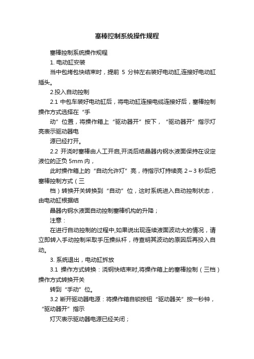
塞棒控制系统操作规程塞棒控制系统操作规程1. 电动缸安装当中包烤包快结束时,提前5分钟左右装好电动缸,连接好电动缸插头。
2.投入自动控制2.1 中包车装好电动缸后,将电动缸连接电缆连接好后,塞棒控制操作方式选择在“手动”位置,将操作箱上“驱动器开”按下,“驱动器开”指示灯亮表示驱动器电源已经打开。
2.2 开浇时塞棒由人工开启,开浇后结晶器内钢水液面保持在设定液位的正负5mm内,此时操作箱上的“自动允许灯”亮,待指示灯持续亮2~3秒后把塞棒控制方式(三档)转换开关转换到“自动”位,这时系统进入自动控制状态,由电动缸根据结晶器内钢水液面自动控制塞棒机构的升降;注意:在进行自动控制的过程中,如果说出现连续液面波动大的情况,请立即转入手动控制采取手压操纵杆,待查明其波动的原因后再投入自动。
3. 系统退出,电动缸拆放3.1操作方式转换:浇钢快结束时,将操作箱上的塞棒控制(三档)操作方式转换开关转到“手动”位。
3.2 断开驱动器电源:将操作箱自锁按钮“驱动器关”按一秒钟,“驱动器开”指示灯灭表示驱动器电源已经关闭;注意:每次断开驱动器电源后须要等待5分钟才能再开驱动器电源。
3.3 拆电动缸插头:驱动器断电后后把电动缸插头拔掉,并将电动缸拆下放至指定存放位置。
4. 电动缸功能检查可在没有拉钢时或使用手动控制时,将电动缸从塞棒机构上取下放在地面上,将操作箱上“驱动器开”按下,“驱动器开”指示灯亮表示驱动器电源已经打开,然后将操作方式转换到“点动”方式,点动电动缸“升、降”按钮, 如与上述动作相反或没有动作则表示电动缸有故障,应通知相关人员进行处理。
5、刻度刻度需用模拟钢坯,钢坯截面积尺寸与铜管口尺寸相当,长度至少为200mm。
在结晶器内有水的情况下,将钢坯吊入结晶器内,使其上表面降至测程下界(离结晶器铜板下190mm)记下此时计数N,作为N0的设定值;将钢坯上提10mm记下此时的计数作为N1的设定值;将钢坯再上提10mm,记下此时的计数作为N2的设定值;将钢坯再上提10mm,记下此时的计数作为N3的设定值;将钢坯再上提10mm,记下此时的计数作为N4的设定值;再将钢坯上提10mm,记下此时的计数作为N5的设定值;将钢坯再上提10mm,记下此时的计数作为N6的设定值;将钢坯再上提10mm,记下此时的计数作为N7的设定值;将钢坯再上提10mm,记下此时的计数作为N8的设定值;将钢坯再上提10mm,记下此时的计数作为N9的设定值;将钢坯再上提10mm,记下此时的计数作为N10的设定值;再用功能键MOD、SEL和VAL给系统输入N0、N1、N2、N3、N4、N5、N6、N7、N8、N9和N10的设定值,将钢坯吊出,刻度完毕。
WA-SBRIE金属杆栓说明书

Dimensions: [mm]AA971300244Cautions and Warnings:The following conditions apply to all goods within the product series of WA-SBRIE ofWürth Elektronik eiSos GmbH & Co. KG:General:•This mechanical component is designed and manufactured for use in general electronic equipment.•Würth Elektronik must be asked for written approval (following the PPAP procedure) before incorporating the components into any equipment in fields such as military, aerospace, aviation, nuclear control, submarine, transportation (automotive control, train control, ship control), transportation signal, disaster prevention, medical, public information network, etc. where higher safety and reliability are especially required and/or if there is the possibility of direct damage or human injury.•Mechanical components that will be used in safety-critical or high-reliability applications, should be pre-evaluated by the customer. •The component is designed and manufactured to be used within the datasheet specified values. If the usage and operation conditions specified in the datasheet are not met, the component may be damaged or dissolved.•Do not drop or impact the components, the component may be damaged.•Würth Elektronik products are qualified according to international standards, which are listed in each product reliability report. Würth Elektronik does not warrant any customer qualified product characteristics beyond Würth Elektroniks’ specifications, for its validity and sustainability over time.•The responsibility for the function of the application of the customer specific products and use in a particular customer design is always the full and autonomous responsibility of the customer. All technical specification for standard products also apply to customer specific products.Product Specific:Cleaning and Washing:•Washing agents used during the production to clean the customer application might damage or change the characteristics of the components. Washing agents may have a negative effect on the long-term functionality of the product.•Using a brush during the cleaning process may damage the component. Therefore, we do not recommend using a brush during the PCB cleaning process.Potting and Coating:•If the product is potted in the customer application, the potting material might shrink or expand during and after hardening. Shrinking could lead to an incomplete seal, allowing contaminants into the components. Expansion could damage the components. Werecommend a manual inspection after potting or coating to avoid these effects. Storage Conditions:• A storage of Würth Elektronik products for longer than 12 months is not recommended. Within other effects, the terminals may suffer degradation, resulting in bad processability. Therefore, all products shall be used within the period of 12 months based on the day of shipment.•Do not expose the components to direct sunlight.•The storage conditions in the original packaging are defined according to DIN EN 61760-2.•The storage conditions stated in the original packaging apply to the storage time and not to the transportation time of the components. Packaging:•The packaging specifications apply only to purchase orders comprising whole packaging units. If the ordered quantity exceeds or is lower than the specified packaging unit, packaging in accordance with the packaging specifications cannot be ensured. Handling:•The maximum permissible torques must be complied with to prevent mechanical destruction of the component and PCB.•If a component is pre-assembled with an adhesive tape, the adhesive duration cannot be guaranteed. This depends on the surface where the component will be mounted on. It also depends on the environmental conditions the component is exposed to. The customer has to evaluate this for his specific application.•Violation of the technical product specifications will void the warranty.•Coated metal parts may have spots and/or deposits because of the rinsing and drying process during plating. The storage and processability are not affected.•The temperature rise of the component must be taken into consideration. The operating temperature is comprised of ambient temperature and temperature rise of the component.The operating temperature of the component shall not exceed the maximum temperature specified.These cautions and warnings comply with the state of the scientific and technical knowledge and are believed to be accurate and reliable.However, no responsibility is assumed for inaccuracies or incompleteness.Würth Elektronik eiSos GmbH & Co. KGEMC & Inductive SolutionsMax-Eyth-Str. 174638 WaldenburgGermanyCHECKED REVISION DATE (YYYY-MM-DD)GENERAL TOLERANCE PROJECTIONMETHODJuSa001.0032020-07-28DIN ISO 2768-1mDESCRIPTIONWA-SBRIE Brass Spacer StudORDER CODE971300244SIZE/TYPE BUSINESS UNIT STATUS PAGEImportant NotesThe following conditions apply to all goods within the product range of Würth Elektronik eiSos GmbH & Co. KG:1. General Customer ResponsibilitySome goods within the product range of Würth Elektronik eiSos GmbH & Co. KG contain statements regarding general suitability for certain application areas. These statements about suitability are based on our knowledge and experience of typical requirements concerning the areas, serve as general guidance and cannot be estimated as binding statements about the suitability for a customer application. The responsibility for the applicability and use in a particular customer design is always solely within the authority of the customer. Due to this fact it is up to the customer to evaluate, where appropriate to investigate and decide whether the device with the specific product characteristics described in the product specification is valid and suitable for the respective customer application or not.2. Customer Responsibility related to Specific, in particular Safety-Relevant ApplicationsIt has to be clearly pointed out that the possibility of a malfunction of electronic components or failure before the end of the usual lifetime cannot be completely eliminated in the current state of the art, even if the products are operated within the range of the specifications.In certain customer applications requiring a very high level of safety and especially in customer applications in which the malfunction or failure of an electronic component could endanger human life or health it must be ensured by most advanced technological aid of suitable design of the customer application that no injury or damage is caused to third parties in the event of malfunction or failure of an electronic component. Therefore, customer is cautioned to verify that data sheets are current before placing orders. The current data sheets can be downloaded at .3. Best Care and AttentionAny product-specific notes, cautions and warnings must be strictly observed. Any disregard will result in the loss of warranty.4. Customer Support for Product SpecificationsSome products within the product range may contain substances which are subject to restrictions in certain jurisdictions in order to serve specific technical requirements. Necessary information is available on request. In this case the field sales engineer or the internal sales person in charge should be contacted who will be happy to support in this matter.5. Product R&DDue to constant product improvement product specifications may change from time to time. As a standard reporting procedure of the Product Change Notification (PCN) according to the JEDEC-Standard inform about minor and major changes. In case of further queries regarding the PCN, the field sales engineer or the internal sales person in charge should be contacted. The basic responsibility of the customer as per Section 1 and 2 remains unaffected.6. Product Life CycleDue to technical progress and economical evaluation we also reserve the right to discontinue production and delivery of products. As a standard reporting procedure of the Product Termination Notification (PTN) according to the JEDEC-Standard we will inform at an early stage about inevitable product discontinuance. According to this we cannot guarantee that all products within our product range will always be available. Therefore it needs to be verified with the field sales engineer or the internal sales person in charge about the current product availability expectancy before or when the product for application design-in disposal is considered. The approach named above does not apply in the case of individual agreements deviating from the foregoing for customer-specific products.7. Property RightsAll the rights for contractual products produced by Würth Elektronik eiSos GmbH & Co. KG on the basis of ideas, development contracts as well as models or templates that are subject to copyright, patent or commercial protection supplied to the customer will remain with Würth Elektronik eiSos GmbH & Co. KG. Würth Elektronik eiSos GmbH & Co. KG does not warrant or represent that any license, either expressed or implied, is granted under any patent right, copyright, mask work right, or other intellectual property right relating to any combination, application, or process in which Würth Elektronik eiSos GmbH & Co. KG components or services are used.8. General Terms and ConditionsUnless otherwise agreed in individual contracts, all orders are subject to the current version of the “General Terms and Conditions of Würth Elektronik eiSos Group”, last version available at .Würth Elektronik eiSos GmbH & Co. KGEMC & Inductive SolutionsMax-Eyth-Str. 174638 WaldenburgGermanyCHECKED REVISION DATE (YYYY-MM-DD)GENERAL TOLERANCE PROJECTIONMETHODJuSa001.0032020-07-28DIN ISO 2768-1mDESCRIPTIONWA-SBRIE Brass Spacer StudORDER CODE971300244SIZE/TYPE BUSINESS UNIT STATUS PAGE。
塞棒操作手册

4)开棒指示:信号点亮(绿色),手动操作或塞棒自动控制时电缸开启指示。
5)关棒指示:信号点亮(绿色),手动操作或塞棒自动控制时电缸关闭指示。
6)塞棒控制自动指示:信号点亮(绿色),塞棒自动控制有效。
4.2.2
手动:信号点亮(绿色),说明目前的系统工作状态为人工操作。
塞棒控制:信号点亮(绿色),说明目前的系统工作状态为塞棒自动控制状态。
拉速控制:信号点亮(绿色),说明目前的系统工作状态为拉速自动控制状态。
4.2.3塞棒控制相关信号状态说明
1)系统急停:信号点亮(红色),系统急停状态有效。
2)驱动器故障:信号点亮(红色),驱动器故障指示。
注意:要考虑其地角螺钉的固定及系统电源、保护接地线、信号电缆的引入是否方便,针对固定长度及长度有限制的电缆要考虑其长度的限制。
2.1.2根据接线图确认现场设备之间和现场设备与电气控制柜之间的走线线路、走线电缆型号及根数、走线电缆长度。
注意:要考虑固定长度及长度有限制的电缆的长度限制;严格按照电气图纸的要求保证备用线的数量;严格避免弱电信号电缆与电压大于24V或与供电功率大于200W的线或电缆并行,如不可避免双方都要用接地铁管屏蔽并要间隔20㎜以上的距离;在弱电信号电缆和电缆电压大于24V或供电功率大于200W的线或电缆交叉时要直角交叉,并要间隔20㎜以上的距离;当与弱电信号电缆并行或交叉的电缆供电功率大于3KW时,不仅双方都要使用接地铁管屏蔽而且其间隔距离要相应的增大;走线的电线或电缆的长度要有0.5m左右的富余。
第三步:塞棒自动控制投入
自动允许指示灯亮后,将”塞棒-0-拉速”三位开关打到塞棒位(左),塞棒自动控制投入,塞棒自动指示灯亮说明塞棒自动控制已经投用。
- 1、下载文档前请自行甄别文档内容的完整性,平台不提供额外的编辑、内容补充、找答案等附加服务。
- 2、"仅部分预览"的文档,不可在线预览部分如存在完整性等问题,可反馈申请退款(可完整预览的文档不适用该条件!)。
- 3、如文档侵犯您的权益,请联系客服反馈,我们会尽快为您处理(人工客服工作时间:9:00-18:30)。
使用说明书
(中美合资)四机赛瓦石油钻采设备有限公司生产的 "MWB"型桥塞是结构紧凑,外表面平滑的桥塞,适用于多种规格的套管。
这种桥塞与其它类型的桥塞相比有直径小、中心管短的特点,因此下放就比较快且简单。
整体式卡瓦避免中途坐封且易钻除。
平滑的金属背圈结构、单胶筒和棘轮锁环在套管和密封件之间组成可靠的密封系统。
在进行射孔作业之前,必须在桥塞上堆积砂子或水泥来给予其充分的保护,这样就可防止对桥塞的冲击破坏。
●结构简单、易下、电缆坐封或液压坐封;
●能可靠的坐封在任何级别(包括P-110)的套管;
●棘轮锁环保持坐封负荷,保证压力变化下仍可靠密
封;
●单胶筒和平滑的金属背圈组成可靠的密封系统;
●整体式卡瓦避免中途坐封且易于钻除;
●推荐用于温度177°C(350°F)、压力70Mpa
(10,000PSI)的工况;
●铸铁结构容易钻除;
●可直接用各种BAKER,GEARHAT,
HALLIBURTON 电缆坐封工具或液压坐封工具坐封。
操作指导
与坐封工具的连接:
1)将BAKER接头包中的调整接头接到BAKER或GEARHAT的电缆或液压坐封工具底部的活塞杆上,用扳手拧紧,并拧紧顶丝;
2)将接头包中的坐封套接到BAKER或GEARHAT的电缆或液压坐封工具上,用扳手拧紧;
3)将锁紧弹簧卡在调整接头下端的缺口内,再将桥塞上的释放栓穿过锁紧弹簧而与调整接头相连,将扳手打在桥塞的套阀上,顺时针旋转桥塞,直到坐封套抵住桥塞上端的背圈,至此连接完成
坐封过程:
" MWB桥塞可按与常规可钻式封隔器或桥塞一样的方法下到要求的坐封深度,桥塞组件的剪切销的设计是作为防止特殊井况引起提前坐封的安全方法。
在下桥塞的过程中,最佳的下放速度为100英尺/分钟(30米/分钟),在坐封过程中,坐封套抵住桥塞外部各组件,而拉杆则提拉桥塞中心管,这个动作使卡瓦坐住,橡胶套胀大,桥塞被压缩坐封,给释放栓加一定的拉力,释放栓被拉断,坐封工具和接头包就可以从井中取出.
桥塞坐封后,将坐封工具提高几英尺,然后缓慢放回,以确定桥塞是否坐封在正确的位置上。
在坐封过程中,指重表可能会有两次跳动,一次跳动是指剪切销被剪断,另一次跳动是指释放栓被拉断。
注意:在桥塞上作业前,须将3米高的沙或水泥堆积在坐封的桥塞上,这样作业的安全就可得到保证,同时能防止震动带来的对桥塞的损坏。
参照下表中的拉力(除去油管净重),即可坐封桥塞
在尽可能的情况下推荐使用上表中的最大拉力,无论在何种情况下,为了确保胶套的充分压缩以及卡瓦的破裂,实际操作中的拉力至少等于上表中的最小拉力。
钻除时的推荐参数、推荐下面成功的钻除水泥承留器所使用的技术参数 :
1. 钻头-------------------------新的,短齿,中等硬度;
2. 转速-------------------------一般为80转/分(如果需要可达120转/分);
3. 钻头上施加的力---------------施加5000到7000磅,直到桥塞中心管外径上端被钻掉(4 1/2"-7"规格的桥塞大约7英寸,180毫米,7 5/8"以及更大规格的桥塞约10英寸,254毫米)之后,可增加重量到钻头上。
增加重量为:钻头直径每英寸为2000到3000磅(例如:钻头直径为4 3/4英寸,则使用12000到14500磅的力量)。
4. 钻铤---------------------------最少8只(4 1/2"和5 1/2")最少12只(7"和更大规格)间断转动钻杆,变化钻杆钻速和施加重量,有利于破坏大块金属和阻止钻头卡钻。
当正常循环时,可在钻头上使用一个或多个落物篮。
液压坐封工具送井的桥塞标准操作规程
本规程作为Baker20#液压坐封工具坐封桥塞的标准操作规范,施工时应严格按照此程序操作
1.施工准备
1.1 坐封工具的保养
1.1.1 拆卸工具各部分(管钳打在非密封面处),清洗各零件
1.1.2 检查零件上的孔、通道,要保持畅通
1.1.3 “O”形圈处涂黄油,螺纹处涂螺纹保护脂
1.1.4 按装配顺序装配,各零件用管钳打紧(管钳打在非密封面处)
1.2 采取必要的措施(套铣、刮削、洗井)保证坐封层位±5m段套管内壁干净、无
垢
1.3 用标准通井规通井
1.4 检查桥塞的上下卡瓦有无裂纹、牙形是否良好,橡胶套表面有无刮伤
1.5 按照使用说明书连接坐封工具和桥塞,要求上卡瓦可径向转动,而轴向无位移;
同时,运输过程中要保护好工具,特别是卡瓦和橡胶套
1.6 检查管柱的密封性能、强度及内径,保证钢球能顺利通过(条件允许时,可采用
新油管)
2.施工过程
2.1下管柱:限速下钻(40-50根/小时),下钻应匀速、平稳,禁止猛停猛放,顿
钻、溜钻,同时要事先判断井内液面的位置,工具与液面接触时,应匀速缓
下,过造斜点、套管悬挂、套变时也要匀速缓下。
2.2 投球:一般采用自由落体到位,(直井不允许泵送),当井底压力大时,可采用
小排量循环送球到位;如果是水平井作业,投球后5min即可大排量泵送。
2.3 坐封:打压时,压力每升高5Mpa,稳压3-5min,当压力达到15Mpa时(4 1/2”-
6 5/8”的桥塞,理论值16Mpa丢手,7”-13 5/8”的桥塞,理论值27Mpa丢手),
可采用下列方法丢手:
2.3.1 缓慢打压直至丢手。
2.3.2缓慢上提管柱直至丢手,推荐使用此方法,上提与打压配合关系见附表。
2.4 探塞:加钻压不得超过5吨,下探桥塞是否下移(过大的钻压可能损坏桥塞)
2.5 验封:各施工单位可以根据自己的施工要求进行验封。
2.6 起管柱,坐封工具取出后及时保养
附表上提与打压配合表。