HDMI画面键鼠分割同步器说明书
HDMI 4画面分割器 用户手册 V1.2版说明书

尊敬的用户:您好!感谢您使用本公司的产品,为了您更好地体验本产品带来的视觉体验效果,我们配备了内容详细的用户手册,在您开始使用本产品之前请先仔细阅读用户手册,您从中可以获得有关产品的介绍、使用方法等方面的知识,以便您能正确的使用本机。
若有不明白之处,请您联系购买的商家!温馨提示:本手册仅供参考使用,若有更新,不再另行通知!《HDMI 4画面分割器》主要介绍了分割器的使用方法、主要性能参数、功能特性、设备的连接及重要的安全说明等信息。
本手册只作为用户操作指示,不作为维修服务用途。
自发行日期起,此后的功能或相关参数若有改变,将另作补充说明,详情可向厂商或各经销商查询。
本手册为本公司版权所有,未经许可,任何单位或个人不得将本手册之部分或其全部内容作为商业用途。
本手册版权受《中华人民共和国著作权法》及其他知识产权法规保护。
未经书面许可不得复印或散布。
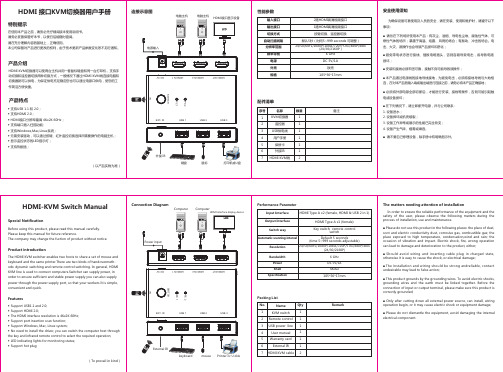
目 录1.产品预览 (1)2.包装目录 (1)3.概述 (2)4.功能特点 (2)5.功能说明 (2)6.遥控器 (4)7.技术参数 (4)8.系统连接图 (5)1. 产品预览前端面板图后端面板图2. 包装目录① 1× HDMI 4画面分割器② 1× 5V/2A DC电源适配器③ 1× 用户说明书④ 1× 遥控器3. 概述5. 功能说明☆ 前端面板端口4. 功能特点HDMI 4x1多画面分割器能将4路HD M I高清输入信号同时在一台电视机上显示,视频分辨率最高支持1080p@60Hz。
此产品支持5种分割模式,在模式范围内,用户可以自由切换4路高清输入,它能够实现单画面显示和单屏显示多画面的功能且支持前面板按键、遥控和RS-232切换可以让用户更方便地使用。
本产品可广泛应用于多媒体广告宣传、大屏幕显示工程等场所。
☆ 兼容HDMI 1.4b, HDCP 1.4和DVI ☆ 视频分辨率达到1080p@60Hz ☆ 支持的音频格式有LPCM2.0☆ 支持5种分割模式☆ 音频输出可以选择任何输入源☆ 支持前面板按键、IR遥控器和RS-232控制5.1 面板介绍☆ 后端面板端口5.2 显示模式多画面分割器有5种显示模式模式1模式2模式3模式4模式5模式1:多画面分割器将分别显示4路高清输入,通过切换前面板的“MAIN”键或IR遥控器将切换为下一个输入信号,顺序为IN1→IN2→IN3→IN4→IN1...模式2:多画面分割器将在一个显示屏上同时显示4个相等尺寸的高清输入信号。
4x4 HDMI开关拆分器4×4(矩阵)由Cat51 HDMI开关分离器说明书
USER MANUALTable of Contents1.0 Introduction (1)2.0 Specifications (2)3.0 Package Contents (2)4.0 Panel Descriptions (3)5.0 Connection and Operation (3)HDMI SWITCH SPLITTERDear customerThank you for purchasing this product. For optimum performance and safety, please read these instructions carefully before connecting, operating or adjusting this product. Please keep this manual for future reference.1.0 INTRODUCTIONThis 4X4 Matrix HDMI SWITCH SPLITTER by cat5e/6 offers unprecedented flexibility and convenience by routing high definition audio/video from any of four HDMI video sources to any of 4 displays over HDMI cable or 4 remote displays over inexpensive, standard CAT5e/6 cable. It eliminates the need to disconnect and reconnect sources to a display equipped with one input.Four receivers work with the Switch Splitter as a full functional module. Full High-Resolution HDTV signals are supported up to a resolution of 1080p over HDMI cable 15m or at a maximum distance of .40M over two pieces of CAT5e/6 cable. The 4X4 Matrix HDMI SWITCH SPLITTER works with HD-DVD players, TiVo systems, HT PCs, and satellite set-top boxes that connect to an HDMI display. Every source and display is accessible at all times by selecting it with an IR remote or through RS232 port.1.1FEATURESThis product has many features that enable it to perform in a superior manner. Among those features you will find:l Allows any HDMI display to view any source at any timel Allows any source to be displayed on multiple displays at the same timel HDMI or DVI to HDMI cables are used to connect the inputs and the matrix outputl Each Output includes one HDMI output and UTP output over cat5e/6, but only one way is available at a time.l Each UTP output is connected to a Receiver.l UTP output extends signal up to 40m for 1080p by CAT-6 cable.l Each Input includes an infrared Emitter, which is used to control the long-distance source device by Remote Control.l Each display's inputs can be switched with the IR remote control or through RS232l Support HDMI1.3bl Support highest video resolution 1080p.l Support 225MHz/2.25Gbps per channel (6.75Gbps all channel) bandwidth.l Support 12bit per channel (36bit all channel) deep color.l Support HDCPl Support uncompressed audio such as LPCM.l Support compressed audio such as DTS Digital, Dolby Digital(including DTS-HD and Dolby True HD).2.0 SPECIFICATIONSSignal Inputs/OutputHDMI Connector type A 19 pin femaleInput DDC Signal 5 volts p-p (TTL)Control Port RS-232 Female, Mini-StereoOutput Signal HDMI output, UTP outputOperating FrequencyVertical Frequency Range50/60HzVideo Amplifier Bandwidth 2.25Gbps/225MHzResolutions(HDTV)Interlaced(50&60Hz) 480i,576i,1080iProgressive(50&60Hz) 480p,576p,720p,1080pMechanicalSize of HDMI Switch Splitter (L-W-H) 441×202×45MMWeight of HDMI Switch Splitter (Net) 2218gWarrantyLimited Warranty 1 Year Parts and Labor EnvironmentalOperating Temperature 0 ℃to +70℃Operating Humidity 10% to 85 % RH (no condensation) Storage Temperature -10℃to +80℃Storage Humidity 5% to 90 % RH (no condensation) Power RequirementPower Supply for HDMI switch splitter 5.5V DC@4A; 20WPower Supply for Receiver 5V DC@2A; 5WRegulatory ApprovalsConverter Unit FCC,CE,ULPower Supply UL,CE,FCCAccessories AdapterAC Power Adapter US standard, UK standard and so on User Manual English versionNote: Specifications are subject to change without notice.3.0 Package ContentsBefore attempting to use this unit, please check the packaging and make sure the following items are contained in the shipping carton:Packaging of Main Unit1) HDMI 4X4 Switch Splitter2) Remote Control3) IR extension cable.(IR)4) 5.5V@4A DC Power Supply 5) User ’s Manual.Packaging of Accessories 6) Four Receivers7) Four pieces of Remote Control for Receivers 8) Four pieces of External infrared emitter (IE) 9) Four pieces of 5V DC @2A Power Supply.4.0 PANEL DESCRIPTIONSPlease study the panel drawings below and become familiar with the structure.HDMI 4X4 Matrix Switch SplitterReceiver321IRPower 4Select5.0 Connection and Operation5.1 Connection1) Connect all source devices to the HDMI inputs on the Switch Splitter..2) Either HDMI or UTP can be selected as signal output for Output A/B/C/D. When choosing the HDMI as signal output, connect displays and main unit directly over HDMI cable. When choosing UTP as signal output, connectreceivers and main unit over cat5e/6 cable, and then connect output of receivers to displays. (Note: HDMI and UTP of each output can not be connected simultaneously)3) Connect the 5.5V@4A power supply to the Switch Splitter, and 5V@2A powersupply to each receiver.Attention: Insert / Extract cable gently.5.2 Operation1) The automatic connection when supplied with powerThe available outputs will automatically connect to the available inputs according to their sequence number. Meanwhile, the redundant available ports (input or output) or unavailable ports will not be connected.For example:1. If outputs A, B, D are connected to three power-on TVs separately, and the four inputs are all have its own source devices (work-on mode), then the power-on Switch Splitter will make a connection as follow:1→A 2→B 3→D(Output C and input 4 are not connected)2. If outputs A, C, D are connected to three power-on TVs separately, and only three inputs have its source devices (work-on mode), then the power-on Switch Splitter will make a connection as follow:1→A 3→C(Output B, output D, input2 and input4 are not connected)2) Selecting source devices by buttonsFour buttons on the Switch Splitter are used to select source devices circularly for inputs A, B, C, and D. Once you press the button, it will select next available source device.4) Selecting source devices by IR remote1. Power buttonThe power button of the IR remote can control the power of the Switch Splitter. Pressing this button, the power-on unit will be turned off. If you press it again, the unit will be turned on.2. Other buttonsDepending on outputs A, B, C, D, the other buttons of the IR remote can be divided into four groups. Each group has five buttons: ‘off’—turn off its outputs. 1, 2, 3, 4 are used to select input port accordingly.5) Selecting source devices by RS232①. Introduction of RS232 remote operation:RS232 remote operation is mainly based on the “super terminal”of Windows operation system. Its parameter should be: ANSI 4800 8-N-1-non②. OperationA. Connect the switch splitter to the COM of PC with a RS232 cable.B. Chose the right COM when you setting “super terminal” and then set theparameter as follow:Baud frequency:4800Data bit: 8Parity bit: NStop bit: 1Data stream: NONC. Inputting your instruction. The instruction should be two or three letter, and finish with “Enter” button.Please input next instruction in three seconds or the”Overtime instruction”will appear.The input instruction should be right, or you will be rejected with the “wrong instruction”If the input or output that you chose is not connected to devices or not in power-on mode, “ineffective instruction” will inform you.If your instruction is performed, you can see the instruction of “successful operation”.③. Instruction input methodA. Selecting source deviceSequence number of output (A/B/C/D) + sequence number of the input (1/2/3/4) + “Enter”For example: If you want display B to view source 3, then you can input “B3 “and finish with “Enter”.B. Turning off an outputC + Sequence number of the output that you want to turn off (A/B/C/D) + “Enter”For example: If you want to turn off output B, then you can input CB, and finish with “Enter”.C. Turning off the Switch Splitter:OFF + “Enter”D. Turning on the Switch Splitter:ON + “Enter”E. Inquiry:QS + “Enter”This order enables you know which input and output are available and the connections of input and output.5.3 CONECTION DIAGRAM。
至龙 HD-SC-500 双 HDMI 和 VGA 切换器 放大器和显示控制说明书

The dual HDMI and VGA switcher w/scaler provides a multisystem solution. Use the HD-SC-500as: a standalone 3 in 1 out switcher for small systems, an analog to digital video converter for systems with no VGA ports, and a scaler for systems with displays that require specific resolutions.Supports scaling of video up to 1920x1200/1080p, VGA conversion and audio embedding and deembedding, the HD-SC-500 has a function in almost any system.• 1 x AT-HD-SC-500• 3 x captive screw female connector (5 pin: audio, 3 pin: RS-232, 2 pin: power)• 1 x Wall/table mount ears• 1 x 5V captive screw power supply (AT-PW5V3.6A-CAPT)• 1 x Installation GuidePackage ContentsDual HDMI and VGA Switcher w/ Scaler and Display ControlAT-HD-SC-500 Installation GuidePlease check /product/AT-HD-SC-500for the most recent firmware update or manual.Panel DescriptionFront Panel1. RS-232 - Connect control system or PC here to control the HD-SC-5002. Firmware - Connect to a PC with a USB cable for firmware updating3. DC 5V - Connect included power supply here4. LAN - TCP/IP (Ethernet) port, connect to router, computer, or control device5. AUDIO OUT - Audio output to audio amplifiers (e.g. AT-PA100-G2) or audio systems6. HDMI IN 2 - Connect HDMI source here (DVI or DisplayPort compatible with adaptors)7. HDMI OUT - Connect to display or extender (e.g. AT-UHD-EX-100CE-KIT)Mounting bracket x 2The HD-SC-500 comes with mounting brackets that can be used to affix the unit to a table, desk, etc.To affix the mounting brackets to the unit, use the four included screws. The bracket can be affixed with the oval holes pointing to the bottom (for against the wall - picture A) or the oval holes facing the top (for under tables - picture B).Larger oval hole will be attached toMountingThe captive screw connectors allow you to cut cables to a suitable length, reducing cable clutter while providing a more reliable connection.Captive ScrewConnectingThe captive screw connectors havea contact bar that is adjusted tocompress the wire against the top contact plate. Use the screws at the top of the connector to compress the wire against the contact plate.When connecting the cables to the female captive screw connector it is important that the wires be terminated correctly. The female captive screw connector has a contact plate at the top and must have the wires touching it for signal to pass. When wired correctly (see picture A) the signal will pass, incorrectly (see picture B) no signal will pass.ClockwiseCounter ClockwiseTurn the screws clockwise toraise the contact bar to theupper contact plate and hold the wires in place.Turn the screws counter clockwise to lower the contact bar to release thewires.BImportant! With unbalanced connections a jumper is needed between ground and negative to reduce noise++++----L / R BALANCEDUNBALANCEDL / R++++--RS-232 pin out will be determined by the RS-232 cable and will connect as Rx (receiver), Tx (transmitter),and (ground). (See picture 4)Female captive screw connectorsare included: Power (see picture 1), RS-232 (see picture 2).The power cable (picture 3) will have exposed wires. Each wire is encased in a different colored cover.1PowerRS-2322Typical pin out:2 - TX - Transmitter3 - RX - Receiver 5 - GND - GroundPin out color will differ per RS-232 cable.Black : - White : +- +34543298761Analog AudioA captive screw analog audio connector is provided to ensure a more reliable and secure connection. The captive screw connector supports balanced and unbalanced audio output.Balanced audio connections use two signal wires and a ground to minimize interference to audio signals. Unbalanced audio connections use one signal wire and a ground and are used if other system components don’t support balanced signals.Note: Pin outs may vary, please refer to the audio device’s manual to ensure a correct connection.Important! When terminating cables, please ensure exposed adjacent wires do not touch. This may result in a short that can damage connected devices.XLRRCA2 ( + )3 ( - )1 ( )Power and RS-232EthernetCategory Cable and ConnectorFor the category cables used in the installation of these products, please be sure to use a 568B termination as pictured below:Connector type and size is very important to ensure extenders work correctly. Please use the matching cable type with the correct RJ45 connector. (e.g. CAT 7 cable should use a CAT 7 connector)Important! 4K (UHD) signals are sensitive to cable quality and installation technique. It is recommended to use CAT6a/7 solid core cables for best results.For convenience, the HD-SC-500 comes with DHCP on. This enables the switcher to beconnected to a network without knowing available IP addresses. If your network does not allow dynamic IP addresses or if you are using the switcher with a TCP/IP control system, this feature may be turned off and the IP address set using front panel.Note: Press and hold the Input button, on the front panel, for 15 seconds to switch between static and DHCP mode. The Display button will flash. Two button flashes means the unit is in static mode and four button flashes means the unit is DHCP mode. Static IP configuration will be: 192.168.1.254 - 255.255.255.0Connection and InstallationTroubleshooting1. My HD-SC-500 is losing its static IP address after rebooting.Please update the unit with the latest firmware.2. I’m not getting any analog audio after rebooting the unit.Please update the unit with the latest firmware.3. The RS-232/IP commands aren’t working for display control.Please update the HD-SC-500 with the latest firmware. In addition, make sure that the unitset to the desired control method (e.g., RS-232, TCP/IP). Be sure to include any end-of-linecharacters (such as CR, LR, etc.) at the end of the command line.4. The Auto-Switch feature isn’t working.Please ensure that Auto-Switching is enabled and that the fallback time is set to at least10 seconds. Auto-Switching can be enabled through the On-Screen Display, w ebGUI, or byusing the AutoSW on command. Fallback time can be set using the webGUI o r by using the ASwOutTime command and should be set to at least 10 seconds. If using Mini DisplayPort-to-HDMI or Mini DisplayPort-to-VGA adapters, make sure that active adapters, which arecompatible with DisplayPort 1.2 or higher, are being used.5. My Mac computer/device is not passing to a codec or video streaming device or it is slow syncing to the display.Set HDCP to “non-compliant.” This setting can be changed through the On-Screen Display, webGUI, or by using the HDCPSet1 off and HDCPSet2 off commands. The HDCPSet1command controls the setting for HDMI 1 In and HDCPSet2 controls HDMI In 2.6. HDCP content (e.g., Blu-Ray, Apple TV) isn’t passing.Set HDCP to “compliant.” This setting can be changed through the On-Screen Display,webGUI, or by using the HDCPSet1 on and HDCPSet2 on commands. The HDCPSet1command controls the setting for HDMI 1 In and HDCPSet2 controls HDMI In 2.7. My HD-SC-500 is not communicating with my control system, using RS-232.Verify that the RS-232 captive screw block is securely connected to the RS-232 port onthe HD-SC-500. Make sure that the captive screw block is wired correctly (see page 4)and that the correct RS-232 settings are being used. The default RS-232 settings for theHD-SC-500 are: baud rate: 115200, data bits: 8, parity: none, stop bits: 1. To test RS-232,connect a computer directly to the HD-SC-500 using a USB-to-RS-232 adapter. Onceconnected to the computer, launch a terminal program, such as Hercules or hTerm, andsend a command. If RS-232 is functioning properly, then RS-232 feedback will be displayed.。
BenQ CP6501K CP8601K 交互式触控显示器 用户手册说明书

CP6501K/CP8601K 交互式触控显示器用户手册免责声明BenQ Corporation 对于本文档的内容不做任何明示或隐含的陈述或担保。
BenQCorporation 保留修订本出版物和随时修改本文档内容而不需通知任何人的权利。
版权版权所有 2020 BenQ Corporation。
保留所有权利。
未经 BenQ Corporation 事先书面许可,不得以任何形式和电子、机械、磁性、光学、化学、手工以及其它任何方式复制、传播和转录本出版物的任何部分,也不得将任何部分存储到检索系统中或翻译成任何语言或电脑语言。
产品支持3产品支持本文档旨在向客户提供最新和最准确的信息,因此所有内容如有修改,恕不另行通知。
请访问网站以获取本文档的最新版本和其它产品信息。
可用文件按型号而有所不同。
1.确认电脑已连接到 Internet。
2.从访问本地网站。
网站布局和内容根据地区/国家而有所不同。
- 用户手册和相关文档: > Business(商用) > SUPPORT(支持) > Downloads(下载) > 型号名称 > User Manual(用户手册)- (仅适用于欧盟)拆卸信息:可在用户手册下载页面中获得。
此文档根据Regulation (EU) 2019/2021 提供,用于维修或回收您的产品。
在质保期内,始终联系当地客户服务中心进行维修。
如果您要维修过质保期的产品,建议您找合格的维修人员,并从 BenQ 获得维修部件,以确保兼容性。
除非您了解后果,否则不要拆卸本产品。
如果您未找到有关您产品的拆卸信息,请联系当地客服中心以寻求帮助。
目录4目录产品支持 (3)安全警告和预防措施 (6)重要安全注意事项 (7)本显示器的注意事项 (7)显示器液晶面板注意事项 (7)遥控器安全注意事项 (8)电池安全指示 (8)BenQ ecoFACTS (9)包装内容 (10)设置显示器 (11)固定显示器 (11)纵向功能 (13)使用相机盖 (17)安装笔座 (18)显示器各部位及其功能 (20)前面板 (20)输入/输出端子 (21)遥控器 (23)使用遥控器 (24)使用主动式触控笔 (26)连接 (31)连接 VGA 输入 (31)连接触摸模块 (31)连接数字输入 (32)连接视频输出 (33)连接到串行端口 (34)连接电源 (35)基本操作 (36)打开或关闭显示器 (36)初始化设置 (37)OSD 设置 (37)目录5切换输入信号 (42)下载软件 (43)设置网络连接 (43)更新软件 (45)调整音频音量 (45)使用触摸屏的重要说明 (50)菜单操作 (51)一键菜单操作 (51)设置菜单 (51)系统设置 (60)Android 系统界面 (67)主界面 (67)Meeting Room 365 (72)应用程序 (80)BenQ Suggests (80)InstaShare (81)InstaShare 2 (83)InstaQPrint (86)WPS Office (87)电子邮件 (89)侧边工具栏 (90)协作+ (91)Blizz (105)Saffi (106)产品信息 (108)规格 (108)尺寸 (CP8601K) (110)尺寸 (CP8601K) (111)支持的输入信号分辨率 (112)故障排除 (114)3/4/21安全警告和预防措施6安全警告和预防措施• 电源线的电源插头应该保持随时可使用。
HDMI接口KVM切换器用户手册
■ Please do not dismantle the equipment, avoid damaging the internal electrical component.
HDMI Type A x1 (female)
Switch way
Key switch, remote control switch
Automatic scanning interval
Default 5 seconds (time 5~999 seconds adjustable)
Resolution
safety of the user, please observe the following matters during the process of installation, use and maintenance.
■ Please do not use this product in the following places: the place of dust, soot and electric conductivity dust, corrosive gas, combustible gas; the place exposed to high temperature, condensation,wind and rain; the occasion of vibration and impact. Electric shock, fire, wrong operation can lead to damage and deterioration to the product, either;
DisplayPort-HDMI 4 个屏幕 KVM 开关说明书

The D2H-4P-Quad offers simplified management between four DisplayPort equipped computers’ USB 2.0 outputs. Keyboards, mice, and other connected USB devices can be switched between with ease. This dynamic KVM console can be controlled via hot keys or RS-232 commands, as well as directly through the console’s easy-to-read front panel.
OVERVIEW
D2H-4P-Quad is a dedicated multi-platform KVM switch capable of managing four 4K computers through a single KVM workstation. Built with ultra-HD ready HDMI outputs, the D2H-4P-Quad is the first Displayport switch on the market to offer full video emulation directly from the device. Up until now, DisplayPort switches lost emulated picture when disconnected from monitors, leading to confusion and disorganization upon reconnecting. With D2H-4P-Quad, full EDID-assisted HDMI video emulation ensures visual workspaces and screen resolutions are remembered every time: simple!
HDMI完全使用手册(详细说明)

HDMI完全使用手册第一章我们为什么需要数字传输接口 (3)第一节数字化影音时代模拟接口的缺陷 (3)第二节HDMI标准横空出世 (4)第三节HDMI标准的主要特性和优势 (6)第二章HDMI技术详细解析 (7)第一节HDMI传输原理解析 (7)第二节HDMI接口类型 (10)第三节HDMI支持的显示格式 (16)第四节HDCP版权保护技术解析 (18)1HDCP版权保护机制的功能 (18)2HDCP实现机制 (19)第五节HDMI标准的发展之路 (20)第六节HDMI音频功能解析 (21)1HDMI音频功能浅析 (21)2HDMI对音频格式支持的变迁 (22)第七节HDMI1.3标准详解 (22)第八节HDMI系统中传输线材的重要性 (25)第三章HDMI标准身后的商业模式 (27)第一节HDMI标准的普及状况 (27)第二节HDMI标准的收费模式 (28)第三节HDMI的"D E FACTO"推广策略 (30)第四章HDMI推广过程中的主要问题 (31)第一节厂商在生产HDMI设备时的问题 (31)第二节HDMI ATC认证的先天缺陷 (32)第三节S IMPLAY HD过高收费带来的障碍 (32)第五章HDMI技术面临的机遇和挑战 (34)第一节HMDI的有力对手—D ISPLAY P ORT技术 (34)第二节HDMI面对的机遇 (35)第一章我们为什么需要数字传输接口第一节数字化影音时代模拟接口的缺陷说起显示设备,很多人都会在第一时间想起电视机和电脑显示器这些在生活中随处可见的设备。
的确,随着人类社会的不断进步,各种显示设备已经在人类社会中发挥了巨大的作用,无论是在工业生产的第一线,还是在家庭休闲娱乐的时刻,人们都希望能看到清晰、流畅的影像。
而对于显示设备来说,要想显示出丰富多彩的高分辨率画面,除了高质量的信号源,还需要一个高性能的信号传输、接收装置,也就是我们常说的信号接口。
8-16-32 USB端口同步器系列搬砖多开说明书

版权保留
C 2017-2019 7
8屏幕
1
2
5
6
3
4
7
8
16屏幕
1
2
5
6
3
4
7
8
9
10
13
14
11
12
15
16
当穿越到上图的黑边框时,水平方向可以循环,竖直方向是不可以的。这样 智能检测方式做是为了防止穿越时能尽快找到鼠标。
2.如果需要取消穿越功能需依次按下“*”和“0”,再依次松开两个按键,即可。 用户第一次使用同步器是,请按下面方法进行设置: 1.设置屏幕分辨率:所有电脑显示器设置成相同的分辨率。 2.设置鼠标:开始>控制面板>指针选项,把“选择鼠标指针移动速度”标杆 设置为中间,把连接同步器的鼠标光标从左下角移动到右上角,如果某个电脑与其 他电脑不一致,调整标杆位置,使其与其他电脑保持一致。
Technical Note
8-16-32 USB端口同步器系列说明书
高清切换器系列产品 TN2016050901 V3.00
产品说明书
感谢您选择我公司产品
为更好地使用本产品,安装前请仔细阅读产品说明书, 并按照说明书进行正确安装和使用。
8-16-32 USB端口同步器
高清切换器系列
1. 产品概述 我公司生产的8-16-32USB端口同步器通过一组设备显示器、键盘、鼠标实
现一个鼠标、一个键盘对多台计算机的操作。从而节省了为每台计算机单独配置 键盘、鼠标、显示器的费用以及它们所占用的空间。
我公司8-16-32 USB端口同步器内置了4个到32个上游USB设备端口、2个下 游USB主机端口、1个PS2主机端口,最多支持32台PC共享一套键盘、鼠标、扬 声器、麦克风及显示器。与PC和设备之间的连接均采用USB方式,支持即插即用, 无需安装驱动程序,简单易用。
- 1、下载文档前请自行甄别文档内容的完整性,平台不提供额外的编辑、内容补充、找答案等附加服务。
- 2、"仅部分预览"的文档,不可在线预览部分如存在完整性等问题,可反馈申请退款(可完整预览的文档不适用该条件!)。
- 3、如文档侵犯您的权益,请联系客服反馈,我们会尽快为您处理(人工客服工作时间:9:00-18:30)。
HDMI USB4X1分割同步器使用说明书概述:通过一套键鼠热键可操作显示单主机单独显示或其他多主机分割模式显示,也可热键操作键鼠的同步操作模式或单独切换操作模式,是键鼠&显示深度融合且显示无缝过度切换。
一、产品概述HDMI USB同步器高清画面分割器是一款高性能的画面分割及USB键鼠同步切换处理设备,其主要功能是使4个主机的高清HDMI信号及USB信号同时以四分割的模式同时显示在一个超高清显示设备上,也可以实现单独显示一个输入信号的模式,同时可以通过一套键盘鼠标实现同步操作或者单独操作4台主机。
高清四画面分割器可以支持4路HDMI视频信号和4路USB输入,1路高清HDMI信号和一套USB键鼠输出,以及一路Audio双声道分离音频输出,所有输入信号均可以实现音视频同步切换;支持红外遥控以及键盘快捷键控制。
产品主要应用于视频会议、监控、教学、展览、展示、游戏、炒股等需要使用单台显示器和一套键鼠同时显示及操作多个高清信号的场所。
二、主要功能►支持单个显示设备同时显示4个高清信号,或切换某一信号全屏显示;►切换单一画面全屏显示,可实现无缝切换,无延时,无黑屏;►支持4路HDMI信号同时输入;►支持1路HDMI输出,输出分辨率最高可达1920*1080@60HZ;►所有输入信号均含音频,支持音视频同步切换;►四分割模式音频可独立切换;►双声道音频分离输出,可接音响及其他音频设备;►支持机箱按扭、红外遥控、键盘快捷键控制。
三、常用分割模式高清HDMI四画面分割器可以设定5种常用的显示模式,如标准四画面分割显示、偏四画面分割显示、二画面分割显示模式、单一画面显示模式、H型画面分割显示,如图所示:4画面模式14画面模式24画面模式3无缝切换模式左右分割模式五、接口及面板说明:设备前面板指示灯及按键功能说明:POWER·······························电源接通指示灯;IN4、IN3、IN2、IN1·························输入接口指示灯;IR··································红外接收端口;4、3、2、1···························单通道无缝切换按键;Mode·························分割显示不同分割模式切换按键;Audio····························音频分离声道切换按键;Reset································设备复位按键。
设备后面板接口及功能说明:DC5V-12V·····························设备电源输入接口;HDMI IN1~HDMI IN4:·······················HDMI输入信号接口;HDMI OUT····························HDMI输出显示接口;Audio·····························双声道音频输出接口;RS232···························此接口为备用接口不可用;USB IN1~USB IN4:····················USB输入信号接口,连接主机;USB OUT····························USB输出接口接键鼠。
六、遥控按键说明:画面分割器可通过遥控进行快速切换,相关按键功能如下:音1、音2、音3、音4:四画面分割模式下可任意选择不同输入通道的音频切换输出;ON/OFF:设备开机关机按键;红框内按键:输出模式切换;Reso:输出分辨率切换;静音:音频静音按键。
七、键盘快捷键说明:A、显示与键鼠同步切换说明1、按住Ctrl加主键盘上的1键来实现输入端口1的单独画面与键鼠的显示控制。
2、按住Ctrl加主键盘上的2键来实现输入端口2的单独画面与键鼠的显示控制。
3、按住Ctrl加主键盘上的3键来实现输入端口3的单独画面与键鼠的显示控制。
4、按住Ctrl加主键盘上的4键来实现输入端口4的单独画面与键鼠的显示控制。
5、按住Ctrl加M键来实现四画面显示与键鼠同步控制。
6、按住Alt加主键盘上的1键来实现取消输入端口1的键鼠控制。
7、按住Alt加主键盘上的2键来实现取消输入端口2的键鼠控制。
8、按住Alt加主键盘上的3来实现取消输入端口3键的键鼠控制。
9、按住Alt加主键盘上的4来实现取消输入端口4键的键鼠控制。
10、鼠标热键:依次按住鼠标左键、右键,再依次松开右键、左键,键盘鼠标对所有电脑同步控制。
B、键鼠同步切换说明1、单击Ctrl加主键盘上的1键来实现输入端口1的键鼠控制。
2、单击Ctrl加主键盘上的2键来实现输入端口2的键鼠控制。
3、单击Ctrl加主键盘上的3键来实现输入端口3的键鼠控制。
4、单击Ctrl加主键盘上的4键来实现输入端口4的键鼠控制。
5、单击Ctrl加M键来实现输四端口的键鼠同步控制。
C、显示切换说明1、双击Ctrl加主键盘上的1键来实现输入端口1的单独画面显示。
2、双击Ctrl加主键盘上的2键来实现输入端口2的单独画面显示。
3、双击Ctrl加主键盘上的3键来实现输入端口3的单独画面显示。
4、双击Ctrl加主键盘上的4键来实现输入端口4的单独画面显示。
5、双击Ctrl加主键盘上的M来实现输入四端口的四画面显示。
D、连发设置说明1、按住ScrollLock+要连发的键值,即设置该键为连发键。
2、按住ScrollLock+Esc,即为清除设置的连发键值。
E、穿越设置说明1、依次按住数字键盘上的*键加主键盘上的S键,再依次松开S键和0键即为启动穿越功能。
2、依次按住数字键盘上的*键加主键盘上的0键,再依次松开0键和*键即为关闭穿越功能。
3、串屏功能说明:a、如鼠标在第一台输入设备显示窗口上,一直向右移动,鼠标可以移动第二台输入设备显示窗口上,再一直向右移动,可以到第三台输入设备显示窗口上...b、如鼠标在第一台输入设备显示窗口上,一直向左移动,鼠标可以移动第四台输入设备显示窗口上,再一直向左移动,可以到第三台输入设备显示窗口上...备注:在显示单屏模式下穿越,画面也随着鼠标一起穿越显示!F、DN模式该功能解决在3D游戏模式下鼠标移动过快问题。