HF5CS32示意图
8255引脚图及引脚功能
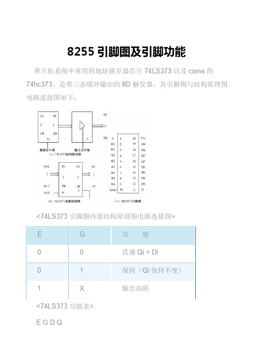
8255引脚图及引脚功能单片机系统中常用的地址锁存器芯片74LS373以及coms的74hc373。
是带三态缓冲输出的8D触发器,其引脚图与结构原理图、电路连接图如下:<74LS373引脚图内部结构原理图电路连接图>E G 功 能0 0 直通Qi = Di0 1 保持(Qi保持不变)1 X 输出高阻<74LS373功能表>E G D QL H H HL H L LL L X Q上表是74LS373的真值表,表中:L——低电平;H——高电平;X——不定态;Q0——建立稳态前Q的电平;G——输入端,与8031ALE连高电平:畅通无阻低电平:关门锁存。
图中OE——使能端,接地。
当G=“1”时,74LS373输出端1Q—8Q与输入端1D—8D相同;当G为下降沿时,将输入数据锁存。
8255A(2)7.2 可编程并行接口由于我们现在常用的微机系统均以并行方式处理数据,所以,并行接口也是最常用的接口电路。
并行接口有以下几方面的特点:(1)并行接口是在多根数据线上,以数据字节(字)为单位与输入/输出设备或被控对象传送信息的,如打印机接口、A/D、D /A转换器接口、IEEE-488接口、开关量接口、控制设备接口等。
在实际应用中,凡在CPU与外设之间同时需要两位以上信息传送时,就要采用并行口。
并行口适用于近距离传送的场合。
由于各种I/O设备和被控对象多为并行数据线连接,CPU用并行口来组成应用系统很方便,故使用十分普遍。
(2)并行传送的信息,不要求固定的格式,这与串行传送的信息有数据格式的要求不同。
例如,异步串行通信的格式是一个数据,它包括起始位、数据位、校验位和停止位。
(3)从并行接口的电路结构来看,并行口有硬线连接接口和可编程接口之分。
硬线连接接口的工作方式及功能用硬线连接来设定,用软件编程序的方法不能加以改变;如果接口的工作方式及功能可以用软件编程序的方法加以改变,则就叫可编程接口。
施耐德CVX系列真空接触器

CVX真空接触器-熔断器组合电器是为满足现代中压空气绝缘开关设备需求而 坚持不懈开发和改进的产品。
概述
CVX真空接触器-熔断器组合电器,是施耐德电气基于全球制造设计经验研 发的新一代产品,采用模块化设计,针对中国市场,适用于KYN28型空气 绝缘开关柜。
CVX组合电器用于需要多次分、合闸操作的场合,可满足用户频繁操作的 需求。
产品结构 ........................................................................................ 4 基本特征 .................................................................................................... 4 结构示意图 ................................................................................................ 4
执行标准
CVX真空接触器-熔断器组合电器符合如下标准: ● GB 14808 ● GB 11022 ● JB/T 7122 ● IEC 60282 ● IEC 60407 ● IEC 62271-200
在国内权威实验室取得的型式实验报告 2
CVX 真空接触器
设计
规格型号
CVX真空接触器-熔断器组合电器以电气保持作为标准配置,也可选配机械自 保持。
二次电路图..................................................................................... 6 CVX 电气保持二次电路图.......................................................................... 6 CVX 机械保持二次电路图.......................................................................... 7
SCV32 新版分解图(洗地车)

Parts and Instructions ManualThis manual is furnished with each new MINUTEMAN SCV TM28/32. This provides the necessary operating and preventive maintenance instructions. Operators must read and understand this manual before operating or servicing this machine.This machine was designed to give you excellent performance and efficiency. For best results and minimal cost, please follow the general guidelines below:·Operate the machine with reasonable care.·Follow the manufacturers suggested maintenance instructions as provided in this booklet.·Use original Minuteman supplied parts.TECHNICAL SPECIFICATIONSModel SCV TM 28/32Model No.SCV28CQP / SCV28DQP / SCV32CQP / SCV32DQPSCV28C / SCV28D / SCV32C / SCV32D / SCV28CPLUSSCV28DPLUS / SCV32CPLUS / SCV32DPLUSCurrent60 AmpsV oltage, Batteries36 volts, 6-6voltBattery Capacity275 Ah (Optional 395 Ah batteries available)Sound Level75 dBDimensions (LxWxH)66" x 31" x 54" (167.64cm x 78.74cm x 137cm)Gross Weight1,243 lbs (564 kg) with batteries(Table of ContentsImportant Safety Instructions (1)For Safety During Operation (1)For Safety When Servicing or Maintaining Machine (1)Inspection (2)Electrical (2)Batteries (2)Operator Responsibility (2)Machine Overview (3)Front (3)Rear (4)Operator Compartment (5)Control Console (6)Key Switch (6)Off Aisle Wand Switch (6)Headlight Switch (6)Battery Gauge (6)Solution Control Knob (6)Mode Selector Knob (6)Horn Button (6)Directional Switch (6)Operation Modes (7)Regular Scrub Mode (7)Heavy Scrub Mode (7)Double Scrub Mode (7)Vacuum Only Mode (8)Transport Mode (8)Solution Control Knob (8)Battery Gauge (8)Fault / Diagnostic Codes (9)Empty Solution Tank Indicator (10)Low Battery Indicator (10)Power Save Mode (10)Operation of Controls (11)Steering Wheel (11)Accelerator Pedal (11)Seat (11)Directional Switch (11)Parking Break (11)Emergency Disconnect Button (12)Circuit Breakers (12)Battery Compartment (12)Battery Connection Diagram (13)Batteries Installed with Spacers (13)Scrub Decks (14)Cylindrical Scrub Deck (14)Disc Scrub Deck (15)Scrub Deck Installation (16)Installation Instructions (16)Important Note when Interchanging Scrub Decks (17)Side Squeegees (18)Disc Deck Side Squeegee Components (18)Cylindrical Deck Side Squeegee Components (19)Brush Changes On the Cylindrical Deck (19)Rear Squeegee (20)Rear Squeegee Components (20)Rear Squeegee Adjustment (21)The SCV Rider (22)Machine Operation (23)After Use (24)Maintenance Schedule (25)Lubricating the Machine (25)General Machine Troubleshooting (26)Exploded Views (28)Main Assembly I (28)Main Assembly I BOM (29)Main Assembly II (30)Main Assembly II BOM (31)Mainframe Assembly I (32)Mainframe Assembly II (33)Mainframe Assembly II BOM (34)Front Drive Assembly (35)Front Drive Assembly BOM (36)Steering Assembly (37)Steering Assembly BOM (38)Solution Tank Assembly / Seat Assembly (39)Solution Tank Assembly / Seat Assembly BOM (40)Electrical Panel (41)Console Assembly (42)Recovery Tank Assembly I (43)Recovery Tank Assembly I BOM (44)Recovery Tank Assembly II (45)Battery Box Assembly (46)Pump Assembly (47)Pump Assembly BOM (48)Rear Axle Assembly (49)Squeegee Mechanism Assembly (50)28” Rear Squeegee Assembly (51)28” Rear Squeegee Assembly BOM (52)32” Rear Squeegee Assembly (53)32” Rear Squeegee Assembly BOM (54)Squeegee Lift Mechanism (55)28” Cylindrical Scrub Deck (56)28” Cylindrical Scrub Deck BOM (57)32” Cylindrical Scrub Deck (58)32” Cylindrical Scrub Deck BOM (59)28” Disc Scrub Deck (60)28” Disc Scrub Deck BOM (61)32” Disc Scrub Deck (62)32” Disc Scrub Deck BOM (63)Cylindrical Scrub Deck Side Squeegee (Left Hand Side) (64)Cylindrical Scrub Deck Side Squeegee (Right Hand Side) (65)Disc Scrub Deck Side Squeegee (Left Hand Side) (66)Disc Scrub Deck Side Squeegee (Right Hand Side) (67)Cylindrical Scrub Deck and Roller Bumper Mounting (68)SCV28CQP & SCV32CQP BOM’s (69)Disc Scrub Deck and Roller Bumper Mounting (70)SCV28DQP & SCV32DQP BOM’s (71)Plumbing Diagram (72)Wiring Diagrams (73)TRIO Connections (73)P3 TRIO Connections (74)P2 TRIO Connections (75)Wire Colors / Codes (76)Minuteman International Made Simple Commercial Limited Warranty (77)Important Safety InstructionsOperators must read and understand this manual before operating or maintaining this machine.Do not operate this machine in flammable or explosive areas.This machine is designed solely for scrubbing dirt and dust in an indoor environment. Minuteman does not recommend using this machine in any other capacity.The following information below may cause a potential hazard to the operator and equipment. Read this manual carefully and be aware when these conditions can exist. Take necessary steps to locate all safety devices on the machine and train the personnel operating the machine. Report any machine damage or faulty operation immediately. Do not use machine if it is not in proper operating condition.For Safety During OperationKeep hands and feet clear of moving parts while machine is in operation.Make sure all safety devices are in place and operate properly. All covers, doors and latches must be closed and fastened before use.During operation, attention should be paid to other persons in the work area and especially if smallchildren are present.Electric motors and components can cause an explosion when operated near explosive materials or vapor. Do not operate this machine near flammable materials such as solvents, thinners, fuels, grain dust, etc.Store or park this machine on a level surface only, with the key switch in the off position. To prevent unauthorized use, machine should be stored or parked with the key removed.This machine is designed for level operation only. Do not operate on ramps or inclines.This machine is not suitable for picking up hazardous dusts.Use caution when moving this machine into areas that are below freezing temperatures. Any water in the tanks or hoses can cause damage to the machine.For Safety When Servicing or Maintaining MachineStop on level surface and turn off machine.Disconnect the power to the machine by pressing the Red Emergency Disconnect Button when charging batteries or during installation or removal of brushes.Avoid moving parts. Do not wear loose jackets, shirts, or sleeves when working on machine.Avoid contact with battery acid. Battery acid can cause burns. When working on or around batteries, wear protective clothing and safety glasses. Remove metal jewelry. Do not lay tools or metal objects on top of batteries.Charging batteries generates explosive gasses. Do not charge batteries when open flames or sparks are present. Do not smoke. Make sure the charger is turned off before disconnecting it from themachine.Charge the batteries in a well-ventilated area with the battery cover removed completely.Do not clean machine with a pressure washer.Authorized personnel must perform repairs and maintenance. Use Minuteman supplied replacement parts.Carefully unpack and inspect your SCV Rider Scrubber for shipping damage. Follow unpacking instructions on shipping pallet. Each unit has been tested and thoroughly inspected before shipment. Any damage is the responsibility of the delivery carrier who should be notified immediately.This machine is battery operated and designed to operate on 36 Volts DC (6) 6-volt batteries.The recommended batteries are rated 275Ah (Minuteman P.N. 956740).We do not recommend mixing Amp Hour capacities. Any alternate battery sets can be used if they are of equal physical size and capacity. See “Battery Compartment” for service and installation.Read this manual carefully before operating this machine.The operator is responsible for taking care of the daily maintenance and check ups of the machine to keep it in good working condition. The operator must inform the service mechanic or supervisor when scheduled maintenance is required as stated in the MAINTENANCE section of this manual.Before starting, familiarize yourself with the machine and its controls (see “Machine Overview, Front”, “Machine Overview, Rear”, “Operator Compartment”, & “Control Console” diagrams).Inspection Electrical BatteriesOperator ResponsibilityA B C D E F G H I Front Drive WheelSide SqueegeeAccelerator PedalSteering Tilt LeverSteering WheelOperator’s SeatRecovery Tank LidRecovery TankControl ConsoleJKLMNOPQRDirectional SwitchSafety LatchBattery CompartmentSolution TankElectrical PanelRear SqueegeeReal WheelScrubdeckRoller BumperMachine OverviewFrontA B C D E F G H Rear SqueegeeRear WheelSide SqueegeeAccelerator PedalSolution TankSteering Tilt LeverSteering WheelRecovery Tank LidIJKLMNOPVacuum Filter AccessVac Inlet AssemblyRecovery TankBattery CompartmentClean-Out CapRecovery Drain HoseRecovery HoseScrubdeckMachine OverviewRearA B C D E Operator’s SeatSolution Tank LidCup HolderSolution TankAccelerator PedalFGHISteering WheelDirectional SwitchControl PanelSafety LatchOperator CompartmentFor operator ergonomics, the control console houses all the primary function controls in acentral area. The key switch and optional headlight and off-aisle wand switches are clustered in the back portion of the console. The directional switch (forward/reverse) is located at the front of the console for easy fingertip operation. The horn button, function selectors, and battery gauge are located in the central part of the console.(A) – Controls the machine’s power (ON/OFF) with a key for safety. All operational settings are retained even when the power is turned off and on. This also serves as a reset switch when errors or faults occur.(OPTIONAL) (B) – ON/OFF control for the water supply to the wand and vacuum motor for the optional Off-Aisle Wand.(OPTIONAL) (C) – ON/OFF control for the optional headlights. (D) - Displays the level of charge remaining in the machine’s batteries. The gauge consists of 10 LEDs. (3 Green, 4 Amber, 3 Red) If the battery life is low, the battery gauge bar icon will be flashing to inform the operator that the machine is almost out of power. Once this signal is displayed, all functions will shut off, including transport mode. The operator must then turn the key switch OFF and then ON to reset the machine. The machine will then have only a few minutes left of reserve power to briefly use Vacuum Only mode to pick up any remaining solution on the floor andTransport mode to return to the charging station. This gauge will also display a fault code if the system has an error. This code is represented by a specific number of flashing LEDs. See Fault/Diagnostic Codes for specific code information.(E) – Adjusts the amount of solution being dispensed to the floor while in one of the scrub modes. Turn the knob clockwise to increase the amount of solution being dispensed. The amount of solution applied is variable to a maximum of 1 GPM.(F) – This knob is used to select the desired operation mode of the machine. See Operation Modes for information about each mode. (G) – Depressing this button will activate the machine’s horn.(H) – Flipping this switch to the down position will set the machine to move forward. Flipping it to the up position sets the machine to move in reverse.Control Console Key SwitchOff Aisle Wand SwitchHeadlight Switch Battery GaugeSolution Control KnobMode Selector Knob Horn Button Directional Switch1.When the machine is running in this mode, the machine will perform all operations. This mode can be used for day-to-day tasks under normalconditions. When the operator sets the directional switch to forward and activates the accelerator pedal, the solution pump will turn on, the brushes will turn on and be lowered to the floor, as well as the rear squeegee. While operating in this mode, the solution will be dispersed into the brushes, which will scrub the floor allowing the chemical in the solution to break down the dirt on the floor. As the machine continues to move forward, the rear squeegee and vacuum system will recover the dirt and dispensed solution. If the operator stops moving, the machine will automatically raise the scrub deck and turn off the brushes. If the directional switch is changed to reverse the machine will continue to operate normally, only the rear squeegee will raise up.2.This mode is similar to Regular Scrub. The machine will continue to operate the same was as if it was in Regular Scrub Mode , only this mode applies more solution and brush pressure is increased. This mode is used for high traffic areas and areas that have been heavily soiled, but do not require time for the solution to soak.3.When the machine is running in this mode, the machine will perform all operations except dirty solution recovery. This mode can be used if the floor is heavily soiled and the chemical will need additional time to emulsify grease and oils that are on the floor. When the operator sets the directional switch to either the forward or reverse position and activates the accelerator pedal, the solution pump will turn on, the brushes will turn on and be lowered to the floor. While operating in this mode, the solution will be dispersed into the brushes, which will scrub the floor allowing the chemical in thesolution to break down the dirt on the floor. As the machine continues to move forward or back, the rear squeegee and vacuum system are not on, which allows the solution to stay on the floor emulsifying the grease and oil. If the operator stops moving in either direction, the machine will automatically raise the scrub deck and turn off the brushes.Operation ModesRegular Scrub Mode Heavy Scrub Mode Double Scrub ModeAfter double scrubbing, the operator should use the vacuum only mode to recover the dirty solution water from the floor.4.When the machine is running in this mode, the machine will only lower the rearsqueegee and turn on the vacuum system to recover the dirty solution from the floor. This mode is usually chosen after double scrubbing to recover the dirty solution but it can also be used to pick up spills. When the operator sets the directional switch to forward , the rear squeegee will be lowered to the floor as the vacuum turns on, pulling the dirty solution water from the rear squeegee into the recovery tank. If the operator stops moving forward and sets the directional switch to reverse, the rear squeegee will retract (protecting it from damage) and the vacuum motor will turn off after a few seconds. If the operator quits moving in either direction, the machine will automatically raise the squeegee and turn off the vacuum motor after a few seconds.5.When the machine is set in this mode, none of the cleaning functions of the machine will operate. This mode is only used to transport the machine from one location to another at a faster rate of speed.6. This control will adjust the amount of solution that is being dispersed to the floor while in one of the scrub modes. Adjust the control clockwise to increase theamount of solution being dispersed. The amount of solution applied is variable to a maximum of 1 GPM.7.This gauge displays the level of charge remaining in the machine’s batteries. The gauge consists of 10 LEDs. (3 Green, 4 Amber, 3 Red) If the battery life is low, the battery gauge bar icon will be flashing to inform the operator that the machine isalmost out of power. Once this signal is displayed, all functions will shut off, including transport mode. The operator must then turn the key switch OFF and then ON to reset the machine. The machine will then have only a few minutes left of reserve power to briefly use Vacuum Only mode to pick up any remaining solution on the floor and Transport mode to return to the charging station. This gauge will alsodisplay a fault code if the system has an error. This code is represented by a specific number of flashing LEDs. See Fault/Diagnostic Codes for specific code information.Vacuum Only Mode Transport Mode Solution Control KnobBattery GaugeFault / Diagnostic CodesWhen an error or fault occurs within the machine, a fault code will appear on the battery gauge represented by a specific number of flashing LEDs. The figure below shows a listing of the different codes.FAULT / DIAGNOSTIC CODES DECALOnce the solution tank has become empty, the battery gauge will blink a solid 9 LEDs at a constant interval to alert the operator that the solution tank needs to be filled.If the battery life is low, the battery gauge bar icon will be flashing to inform the operator that the machine is almost out of power. Once this signal is displayed, all functions will shut off, including transport mode. The operator must then turn the key switch OFF and then ON to reset the machine. The machine will then have only a few minutes left of reserve power to briefly use Vacuum Only mode to pick up any remaining solution on the floor and Transport mode to return to the charging station.The SCV is equipped with a power save feature to conserve battery power. If the key switch power is left ON and none of the controls are activated for a period of fifteen minutes, the SCV automatically goes into “power down mode” and turns OFF the power to conserve your batteries in case the operator forgets to turn the key switch off or leaves the machine unattended.Empty Solution Tank Indicator Low Battery Indicator Power Save ModeThe steering wheel is adjustable for operator comfort by pulling the tilt-steering lever up and positioning the steering wheel up or down (there are three possible positions). Pulling on the tilt-steering lever andpositioning the steering column in an upright position provides the operator with more room whenclimbing up and down the machine.Located on the right side of the operator compartment on the floor is the accelerator pedal. This pedal controls the propelling speed of the machine. The farther the pedal is pushed down the faster the machine will travel. As discussed earlier, thedirectional switch governs the direction of travel the machine will take. Switching the directional switch with the pedal depressed will make your machine changedirections (a very slight delay may occur before the direction of travel changes when switching directions on the fly). The accelerator pedal is interlocked with the seat switch, making machine propulsion not possible without the operator sitting on the seat. The accelerator pedal is also linked to the machine’s dynamic braking system . During operation, when the accelerator pedal is released, the dynamic braking system will automatically halt the movement of the machine without need for an additional brake pedal.The ergonomically designed seat is located on top of the solution tank. There is a lever under the seat that allows the operator to adjust the seat forward or backward for operator comfort. There is an interlock switch located inside the seat. This makes it impossible to engage the traction drive circuitry without the operator on the seat. If the operator were to fall off the machine, the traction drive circuitry would turn off.Located on the lower front of the control console, this switch controls the direction in which the SCV will move when the accelerator pedal is activated. Flipping thisswitch to the down position will set the machine to move forward. Flipping it to the up position sets the machine to move in reverse.This machine is equipped with an Electro-magnetic brake built-in on the traction drive motor. When the machine’s power is turned off (using either the key or theemergency button), the E-mag brake is activated and the traction motor is prevented from moving.Operation of ControlsAccelerator Pedal Seat Directional Switch Parking Break Steering WheelThis button is located in the middle of the electrical panel that is directly underneath the operator’s seat. When the red emergency button is pressed, power will be turned off. Use this button in case of a machine emergency. The red knob needs to be raised in order to run the machine. To reactivate, turn the knob as shown by the arrows on the switch and the button will pop up. All operational settings are retained evenwhen the power is turned off and on.The circuit breakers are located next to the emergency disconnect button. The 6-amp breaker (indicated by black arrow) protects all auxiliary circuits on the machine. The 100-amp breaker (indicated by white arrow) protects the main system circuit (TRIO controller). Each main component is individually protected with an internal breaker built-in the controller. (See fault code table) and can be reset by turning the key switch off a few seconds and then on again. The 100 amp circuit breaker can also be used as a main powerdisconnect, this should be used only in case of emergency. When tripped the breaker removes power from the main controller and all auxiliary power circuits.The battery compartment is located on the rear of the machine under the recovery tank. Unlatching the two safety latches on the side of the machine enables the operator to tilt the recovery tank and access the batteries for servicing and maintenance (make sure recovery tank has been drained before tilting). The battery compartment contains six, 6-volt batteries connected in series. Connect the batteries according to the batteryconnection diagram (see diagram ). The recommended batteries are 275Ah (Minuteman P.N. 956740). The two batteries positioned in the center are offset and held in position by two steel spacers. These spacers keep the batteries from sliding inside the batterycompartment during machine use and prevent undesired stresses in the battery cables. Be sure to replace these spacers whenever reinstalling batteries.Emergency Disconnect Button Circuit Breakers Battery CompartmentBattery Connection Diagram ArrayBatteries Installed with SpacersMinuteman offers two deck types (Cylindrical and Disc) to fit your specific needs. The SCV design is very dynamic wherein the decks are interchangeable in a matter of minutes whenever necessary (removal of four bolts, one hose, and one electrical connection). The cylindrical brush deck has five built-in spray jets to uniformly dispense cleaning solution on the floor and a wet sweeping debris tray to collect loose objects on the floor. The disc brush deck dispenses cleaning solution through the two center hubs and the solution is contained within the bristle area for efficient agitation of cleaning solution to the floor and channeled to the rear of the machine. The disc brushes are also easily removed and installed by easily removing the side deck covers and releasing the quick release clamp. Another nice feature that these scrub decks have is the ability to have uniform brush pressure applied to the floor at all times. Since the scrub deck brush pressure is computer controlled, it will automatically adjust and compensate to uneven contours on the floor while maintaining brush pressure.A B C D E F G H Main HousingSpray Bar w/ SprayjetsAccess Door (2)Access Door Wingnut (6)Debris BoxWater Supply Hose ConnectionMounting BracketPower ConnectorIJKLMNOBrush Motor (2)Pulley Cover (2)Bolt (4)Helical Lock Washer (4)Flat Washer (4)Black Squeegee Adj. Knob (4)Yellow Brush Access Knob (2)Scrub Decks Cylindrical Scrub DeckA B C D E F G Center Deck CoverSide Deck Cover (2)Brush MotorMounting PlateSolution Feed HosePower ConnectorThree Sided Knob (4)HIJKLMBolt (4)Helical Lock Washer (4)Flat Washer (4)Wing Nut for Squeegee Adj. (4)Helical Lock Washer for Squeegee Adj. (4)Flat Washer for Squeegee Adj. (4)Disc Scrub DeckWhen installing a cylindrical deck to a machine:1. Install brushes after the deck has been mounted to avoid flat spots on the brushes.2. Use a piece of cardboard underneath the deck to prevent scratches to the paintedsurface when sliding the deck under the machine.3. Make sure the scrub deck is oriented correctly with the spray jets towards the frontof the machine.hen installing a disc scrub deck to a machine:1. Install brushes on the scrub deck; this aids the installer in sliding the deck assemblyinto position.2. Make sure the scrub deck is oriented correctly with the solution hose tee fittingtowards the front of the machine.1. Park the machine on a flat or level surface.2. Turn the key switch to the ONposition and select the transport modewith mode selector knob.3. Slide the scrub deck assemblyunderneath the machine (followinstructions as described above)4. Position the scrub deck to align themounting brackets with the mountinglugs on the lift linkage.5. Lower the lift linkage to the floor bypressing the manual override switch forfive seconds. (see figure)6. Lower the lift linkage mounting lugsuntil they barely touch the scrub deckmounting brackets.Manual Override Switch, locatedbehind electrical panel.7. Fasten with the four (4) 711242 bolts, 711515 flat washer and 711546 lock washer.8. For cylindrical scrub deck only :a. Remove the Yellow 3 sidedknob on the side squeegeeassembly and swing out the sidesqueegee to reveal the accessdoor.b. Remove the two access doors(one on each end) by removingthe three wing nuts on each door.c. Install the brushes by slidingthem through the accessopening. (see figure for correct orientation.)Scrub Deck Installation Installation Instructionsd. Align the notches on the brush with the drive pins on the hub.e. Push the brush all the way in until it bottoms out.f. Insert the access door hub into the other end of the brush.g. Reinstall the wing nuts and yellow 3 sided knobs and tighten.As previously mentioned, the scrub deck brush pressure is computer controlled. However, when interchanging the two types of decks, an additional step must be taken to ensure that the controller correctly compensates the pressure for the type of deck that is currently installed.Inside the main electrical box, beneath the seat there is an Orange/Violet jumper wire (shown disconnected in Figure 1) that may or may not be connected to the terminal block, depending on the type of scrub deck that was originally ordered with the machine. When using the Disk Scrub Deck, the wire is disconnected. When using the Cylindrical Scrub Deck, the wire is connected to the terminal block located in the electrical box, beneath the TRIO Controller. This terminal block is divided into five sections, each separated by a divider. The four leftmost sections contain one column each of spade terminals. The section on the right contains two columns of spade terminals (this section also contains four Red/Black wires, not shown in Figure 2 for clarity). The Orange/Violet wire must be connected to a spade terminal in the section with two columns when using the Cylindrical Scrub Deck ONLY!When switching from the Cylindrical Scrub Deck to the Disk Scrub Deck, be sure to disconnect the Orange/Violet wire. When switching from the Disk Scrub Deck to the Cylindrical Scrub Deck, connect the Orange/Violet wire to any available spade terminal in the section that contains two columns (shown in Figure 2) and the Red/Black wires.Figure 1 Figure 2Jumper wire disconnected Jumper wire connected to terminal block Important Note when Interchanging Scrub Decks。
FH8523中文数据手册
目录
1、概述 ..........................................................................................................................................................4 1.1 基本特征 ..............................................................................................................................................4 1.2 FH8523 系统框图 .............................................................................................................................5
FH8523 高性能 CMOS 图像信号处理芯片 数据手册
IAP15F2K60S2仿真芯片加MAX3232的在线调试电路图

STC单片机片上仿真法文/杜洋有单片机初学者问了我这样一个问题:单片机真是个好东西,可以实现我的很多想法,就是在编程开发的时候太麻烦,每次改动都要重新编译、下载,再等待着问题的出现。
仅调试一个参数就要花上几个小时的时间。
对于我们这些没什么经验的编程菜鸟来说太麻烦了。
我想单片机技术发展至今,应该有更便捷的开发工具吧。
杜老师你平时是怎么开发单片机软件的?有什么秘诀传授一下呗!我的回答是:当然有秘诀,那就是使用“仿真功能”。
什么是仿真?它如何实现更快捷的开发呢?详见下文。
【什么是仿真】什么是仿真?我们举一个汽车设计的例子来说明一下吧。
大家一定在影视剧或电视广告中看过这样的镜头:在一个大大的厂房里,一辆崭新的小汽车正在以很高的速度撞向一面厚厚的水泥墙。
坐在车上的两个人面不改色心不跳,一动不动地等待着死亡。
他们为何如此冷静,因为“他们”是实验用的假人。
说时迟那时快,汽车已经撞到了墙上,巨大的声响夹杂着飞溅的碎片充满了空间,汽车在撞击中破了相。
旁边的几台高速摄像机记录下了这一切。
这是一次真实的撞击实验,目的是为了得出这款车型在出现意外时,是否能保住人的小命。
安装在假人身上的传感器所得出的数据,能帮助工程师们发现安全隐患,改进汽车的设计。
可以说以上就是一次仿真,一辆真车和两个假人有计划地撞墙,模拟了真实车祸情况。
仿真让实验变得可能,因为没有一个真人愿意坐在车里参与这场实验。
当真实情况很难在开发时再现时,仿真就可以帮助开发者完成必要的实验。
这就如同单片机开发中,我们在自己的实验板上去开发一款产品一样。
当我们设计好了一个产品的功能,我们要在实验板上模拟用户的操作,看看操作是否正常,产品的反应速度和稳定性如何。
这些都是在仿真——模仿用户使用的真实情况。
有朋友会问了:如果这就是仿真,那还有什么好讲的呢?嗯,如上所说的仿真只是广义上的仿真,凡是在实验室里用实验板或工程样机模拟用户使用的过程,都可以算是仿真。
而还有一种狭义的仿真,就是下面要重点介绍的内容。
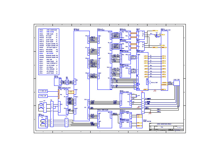
HF50-R图纸——标注
TB2-15 TB2-14
CZ1-6,14 CZ1-5,13
HF5005A FILAMENT DRIVER1 AC220V PFA1-5 AC0V
PFA1-6 PFA1-1 PFA1-2 TB1-4
40V 0V
灯 丝
PP5-5 PP6-1 PP5-2 PP5-4
TB4-5 TB4-6 TB4-8 TB4-7 TB4-13 TB4-12
TB2-15 TB2-8 TB2-16 PP1-4 PP6-4
NF2 NF2-1 AC NF2-3
TB2-6
A
TB2-30 HAND1 COM HAND2 0V +12V TB2-17 TB2-18 TB2-19 TB2-20 0V +12V
PS3 1 2 3 4
X-RAY TUBE FOR MA TEST
ANODE CATHODE
ANODE CATHODE
GND
GND B
TO WALL AEC
PT6 PT4 TB2 17
16
CZ3
HAND1
1
HAND2
2 4
3 PT3 2 PT5 1
1 2 3 4 5 6 8
/AECEXP /TOMO /LEFT /CENTER /RIGHT /RESET /TABLE
N
N
N
TB1-4
N
TB3-3
KL1-A1 KL1 KL1-A2
TB3-6 TB3-1
KL2-A1
GND
GND
KL2 KL2-A2
TB3-8
NF1 NF1-1 AC AC NF1-3
AC1
SW1 5V G1
TB2-6 0V TB2-8
厦华彩电15液晶电视机电路图纸线路图原理图
A
VCC
B
R73 150 OHM
2
C
Title Size A4 Date: File: 2006-11-13 Sheet 9 of 10 C:\Documents and Settings\..\ADC08031V5.Sch Drawn By: 4 Number Revision
D
2.0
G.Q.ZHU O
C131
D
Video Decoder and Connector
Size B Date: File: Number
VPC3230
6
Revision 2.0
2006-11-13 Sheet 8 of 10 C:\Documents and Settings\..\VIDEOV5.sch Drawn By:
FB1IN B1/CB1IN G1/Y1IN R1/CR1IN B2/CB2IN G2/Y2IN R2/CR2IN CIN VIN1 VIN2 VIN3 VIN4
VGAV
o f in
V33 AVCC 10 26 29 36 45 52 VSUPD VSUPPA VSUPLLC VSUPY VSUPC VSUPSY VSTBY VSUPF VSUPAI 59 69 76 INTLC VS MSY/HS AVO LLC1 LLC2 Y7 Y6 Y5 Y4 Y3 Y2 Y1 Y0 53 57 56 54 28 27 31 32 33 34 37 38 39 40 C7 C6 C5 C4 C3 C2 C1 C0 41 42 43 44 47 48 49 50 FFOE FFRE FFRSTW FFWE FFIE FSY/HC FPDAT CLK20 CLK5 GNDCAP GNDPA GNDLLC GNDD1 VOUT VREF VRT 23 22 21 20 19 55 58 24 60 70 78 66 ASGF1 ASGF2 GNDY GNDF GNDAI GNDC GNDSY ISGND AISGND U11 VPC3230 12 25 30 11 AVCC PIN 59 C129 0.1uF C132 10uF Title 7 64 35 65 77 46 51 68 80
CS6552、CS6552F离线式小功率AC-DC恒流开关电源芯片
○:表示该有毒有害物质的含量在 SJ/T11363-2006 标准的限量要求 以下。×:表示该有毒有害物质的含量超出 SJ/T11363-2006 标准的 限量要求。
-7-
f
VLED N2 * P 2 8 * I LED * LP N S
2.2.4 、前沿消隐 由于存在寄生电容, MOSFET 在导通瞬间,会产生一个脉冲电流。 CS6552/CS6552F 内部集成有前沿消隐功能,当 MOSFET 导通的瞬间,设计有 500ns 的前沿消隐时间,在这 段时间内,电流比较器停止工作,避免脉冲电流让电流比较器发生误翻转。
dip82功能框图与引脚说明1功能框图逻辑控制重启zcd过零检测过温保护outvccgndcs600v驱动电压调制偏置基准电压欠压保护内部电压峰值电流限制2功能描述cs6552cs6552fled恒流驱动芯片集成600v高压功率管采用原边反馈控制技术无需光耦等次级反馈环路具有高精度的led恒流输出极大的节约了成本
● 封装形式: DIP8
2、功能框图与引脚说明
2. 1 、功能框图
OUT
VCC
电压调制 & 偏置 欠压保护
基准电压 内部电压
过温保护
逻辑控制 & 重启 Q
600V 驱动
R
ZCD
过零检测 S
峰值电流限制 & 前沿消隐
GND
CS
-1-
MOS 电路
CS6552/CS6552F
高精度原边反馈 LED 恒流驱动电路
2. 3 、引脚排列图
GND ZCD VCC CS
1
8
NC NC OUT OUT
GND ZCD VCC CS
1
8
NC NC OUT OUT
大连东福彩色液晶显示器有限公司EDM12232A液晶显示模块使用手册说明书
EDM12232A 图形点阵式液晶显示模块使用说明1. 使用范围----------------------------------------------------22. 质量保证----------------------------------------------------23. 性能特点----------------------------------------------------24. 外形图-------------------------------------------------------65. I/O接口特性-----------------------------------------------76. 质量等级---------------------------------------------------167. 可靠性---------------------------------------------------198. 生产注意事项---------------------------------------------199. 使用注意事项---------------------------------------------20第 2 页共 19页第 3 页 共 19页1、使用范围该检验标准适用于大连东福公司设计提供的标准液晶显示模块。
如果在使用中出现了异常问题或没有列明的项目,建议同最近的供应商或本公司联系。
2、质量保证 如在此手册列明的正常条件下使用、储存该产品,公司将提供12个月的质量保证。
3、性能特点3-1.性能:显示方式 : 半透、正显黄绿色 STN LCD 显示颜色 : 显示点: 深蓝色背景:黄绿色显示形式 : 122(w)×32 (h) 全点阵 输入数据 :来自MPU 的8位并行数据接口驱动路数 : 1/32 Duty视 角 :6 点3-2.机械性能:项 目 规 格 单位外形尺寸 81.0(W)×47.0(H)×10.0MAX(T) Mm 显示点阵数 122(W)×32(H) Dots —视 域 71.0(W)×23.0(H) Mm 显示图形域 65.83(W)×17.23(H) Mm 点间距 0.54(W)×0.54(H) Mm 点尺寸 0.49(W)×0.49(H) Mm 重量 Approx. 145 G3-3. 极限参数:项目 符 号 最小值最大值 单位注 释 逻辑 Vdd -0.3 7.0 V 电源电压 LCD 驱动 Vdd – Vee 0 13.5 V 输入电压 Vi -0.3 Vdd+0.3V 操作温度 Top 0 50 ℃ 储存温度 Tstg -20 60 ℃湿度 — — 90 %RH第 4 页 共 19页3-4. 电气特性:3-4-1 电气参数项 目 符 号 条 件 最小值典型值 最大值 单 位 逻辑 Vdd 4.5 5.00 5.5电源电压LCD 驱动 Vdd–Vee -7.0 — 5.3高电平 Vih Vdd=5V ±5% 0.8Vdd — Vdd输入电压低电平 Vil 0 — 0.2VddV频 率 Fflm Vdd=5V 70 75 80 Hz逻辑 Idd — — 2.0功 耗 LCD 驱动 Iee Vdd=5V Vdd–Vee=5.2VFflm=75Hz — — 1.0mA Ta= -20℃φ=0°,θ=0°— 5.2 —Ta= 25℃φ=0°,θ=0°— 5.0 — LCD 驱动电压 (推荐电压) Vdd–Vee Ta= 60℃φ=0°,θ=0° — 4.8 —VNote: <1> 驱动路数=1/32 <2> 所有点在静态条 3-5. 电光特性项 目 符号温度 条件 最小值典型值最大值 单位 注释 -20℃ — 5.5 —25℃ — 5.0 — LCD 驱动电压 (推荐电压) V LCD 60℃ φ=0°,θ=0°— 4.5 — V 1,2,5-20℃ — 1500 2000 上升时间 tr25℃ — 150 200 -20℃ — 3000 3500响应时间 衰退时间 td 25℃ φ=0°,θ=0° — 200 250Ms 1,3,5垂直 -35 — 35视 角Δφ 25℃水平 -30 — 30 deg. 1,4,5对比度 K 25℃ φ=0°,θ=0°2.0 5.0 — — 1,5,6注意:<1> φ和θ的定义<2> 在此电压范围内能获得对比度大于2(k≥2)第 5 页共 19页第 6 页 共 19页注意:<6> 对比度定义(K)正显负显非选择点的亮度(B2) 选择点的亮度(B1)4、外形图5、I/O 接口特性5-1. I/O 接口表:管脚号 符号 功 能 1 A0 显示数据.指令数据控制信号 2 E2 使能信号 3 R/W 读写控制信号 4 RES 复位 5 E1 使能信号 6 GND 接地 7 VEE LCD 驱动电压 8 VCC 电源 9-16 DO-D7 数据线5-2.时序及时序图:项目 符号 条件最小值 最大值 单位 E 使能信号周期 Tc 1000 — E 高电屏保持时间 Twh 450 — E 低电屏保持时间 Twl450 — E 上升时间 Tr — 25 E 下降时间 Tf — 25R/W 建立时间 Tasu140 —R/W 保持时间 Tah10 — 数据上升时间 Tdsu 200 — 数据延时时间 Td — 320 写数据保持时间 Tdhw 20 — 读数据保持时间 Tdhr Vdd=5V ±5%Vss=0V Ta=25℃ 10 —ns 时序图如下:(a) 写时序图(b)读时序图电源连接图5-3.5-4. 电路图解(图解参见Fig.5-4)LCD模块需逻辑电压(Vdd)和LCD驱动电压(Vee)注释: 当信号线直接连到C-MOS电路且没有内部上拉或下拉电阻时,有必要隔离外部干扰来保护信号线。
GT30L32S4W规格书V1.1I_A
8.1 GB2312 1 区字符 (846 字符) ........................................................................................................................................................27 8.2 8×16 点国标扩展字符(126 字符) .............................................................................................................................................30 8.3 8×16 点特殊字符(64 字符) .......................................................................................................................................................31