热风炉中英文说明书
热风炉使用说明书
热风炉使用说明书热风炉使用说明书1、引言本使用说明书旨在提供热风炉的详细使用方法和注意事项,以确保用户正确、安全地操作和维护热风炉。
请您在使用前仔细阅读本手册并按照说明进行操作。
2、热风炉概述2.1 热风炉的用途热风炉主要用于产生高温空气供热用途,包括烘干、热处理、烟道除尘等工业领域。
2.2 热风炉的组成热风炉由燃烧器、炉膛、烟道系统、供热系统等主要组成部分。
燃烧器用于燃烧燃料,炉膛是燃烧和传热的空间,烟道系统用于排出燃烧产生的废气,供热系统则将高温空气输送到需要加热的地方。
3、热风炉的操作3.1 开机操作3.1.1 确保热风炉处于关闭状态。
3.1.2 检查燃油或燃气供应是否充足。
3.1.3 打开燃料和气源阀门。
3.1.4 打开燃烧器点火开关,等待点火成功。
3.1.5 观察燃烧情况并调节燃料供给量,使炉膛达到所需温度。
3.2 运行过程中的操作3.2.1 定期检查燃烧器和炉膛的工作状态。
3.2.2 保持燃烧器和炉膛的清洁,定期清除积碳和灰尘。
3.2.3 注意安全,定期检查燃烧器和炉膛的防护装置和安全阀。
3.3 关机操作3.3.1 关闭燃料和气源阀门。
3.3.2 等待炉膛冷却。
3.3.3 关闭燃烧器点火开关。
4、热风炉的维护4.1 清洁维护定期清洁炉膛,除尘系统和烟道系统,确保排出的废气符合环保要求。
4.2 润滑维护定期检查和更换热风炉的润滑油,确保各部分运转良好。
4.3 保养维护4.3.1 定期检查燃烧器和炉膛的工作状态。
4.3.2 检查燃料和气源供应管道是否正常。
4.3.3 确保安全装置和控制系统的正常运行。
5、法律名词及注释5.1 燃油、燃气:指热风炉的燃料来源。
5.2 炉膛:热风炉的燃烧和传热的空间。
5.3 烟道系统:用于排除燃烧产生废气的管道系统。
5.4 供热系统:将高温空气输送到需要加热的地方的系统。
6、附件本文档所涉及的附件详见附件部分。
热风炉中英文说明书

JDK型空气加热器(热风炉)使用说明书Operation Manual of JDKType Air Heater常州市鼎龙环保设备有限公司常州市鼎马干燥机械有限公司Changzhou Dinglong Environmen Protection Equipment Co., Ltd.Changzhou Dingma Drying Machinery Co., Ltd.二00八年敬告用户Notice抽板式链条炉排调风和清灰系统为一体。
Air regulation and dust cleaning system of drawerpanel-type chain grate is a whole.操纵拉杆每2小时往复拉动清灰后复位至需要的风门开度,切记!!!After reciprocating pull and dust cleaning every 2 hours, please reset the control operating rod, and ensure the properopening of the throttle. DO REMEMBER!!!CONTENT1. 概述Summary (1)2. 结构性能简介Brief Introduction of Structural Performance (2)3. 系统图及说明System Drawing and Explanation (3)4. 点火及启动Ignition and Starting (4)5. 烘炉Heat furnace (5)6. 正常运行Normal Operation (6)7. 链条炉排的运行操作和调节Operation and Adjustment of Chain Grate (7)8. 设备保护Protection of the Equipment (12)9. 系统清灰及清渣Dust Cleaning and Slag Removal for the System (13)10. 停炉Shutdown of the Stove (14)11. 维护和保养Maintenance (15)12. 附:沉降室热风炉的清灰 (17)Appendix: dust cleaning of hot blast stove with settling chamber (17)1.概述SummaryJDK系列空气加热器(也称热风炉)是一种以煤为燃料,以空气为介质的新型高效的换热设备,能连续提供恒温、恒压、无尘的干净热空气,广泛应用于纺织漂染、橡胶涂层的热定型;印铁涂料烘房、金属表面除锈处理后的烘干及油漆烘干,造纸工业的烘干,粮食饲料、谷物鱼粉、烟叶茶叶等的烘干;胶合板、石膏板的成型干燥,木材干燥,化工物料、动植物油脂的喷雾干燥以及工业厂房的采暖等等。
电厂生产中英文对照手册
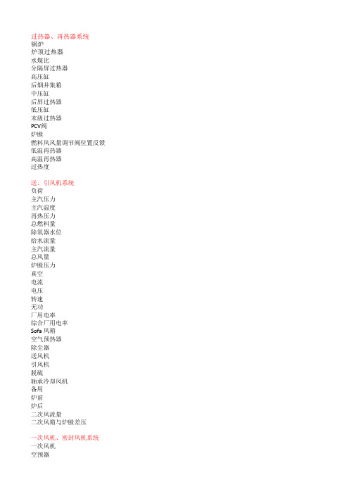
过热器、再热器系统锅炉炉顶过热器水煤比分隔屏过热器高压缸后烟井集箱中压缸后屏过热器低压缸末级过热器PCV阀炉膛燃料风风量调节阀位置反馈低温再热器高温再热器过热度送、引风机系统负荷主汽压力主汽温度再热压力总燃料量除氧器水位给水流量主汽流量总风量炉膛压力真空电流电压转速无功厂用电率综合厂用电率Sofa 风箱空气预热器除尘器送风机引风机脱硫轴承冷却风机备用炉前炉后二次风流量二次风箱与炉膛差压一次风机、密封风机系统一次风机空预器暖风器密封风机密封风机轴承温度火检冷却风机给煤机密封风磨煤机冷一次风磨煤机热一次风炉膛炉顶过热器炉膛分隔屏过热器后烟井集箱后屏过热器末级过热器低温再热器高温再热器省煤器空预器烟温探针炉管泄漏报警灰渣泵锅炉主启动系统负荷主汽压力主汽温度再热压力总燃料量除氧器水位给水流量主汽流量总风量炉膛压力真空电流电压转速无功厂用电率综合厂用电率炉顶过热器大气式扩容器分隔屏过热器集水箱后烟井集箱水冷壁进口集箱后屏过热器水冷壁中间集箱末级过热器水冷壁出口集箱分离器水冷壁温度高辅助蒸汽启动锅炉锅炉二次风系统煤燃烧器油燃烧器Sofa风喷嘴上层下层锅炉制粉系统原煤斗给煤机磨煤机炉膛疏通机炉膛角电动机轴承温度电动机铁芯温度冷一次风热一次风密封风磨辊升到位变加载形式启动停转运行锅炉疏水系统给水疏水扩容器大气给水泵省煤器水冷壁进口集箱分离器水冷壁中间集箱炉顶过热器水冷壁出口集箱分隔屏过热器低温再热器后烟井集箱高温再热器后屏过热器末级过热器煤燃烧器状态磨煤机启动允许冷一次风挡板开度热一次风挡板开度磨辊降到位二次风变加载方式锅炉光字牌报警炉膛压力高炉膛压力低总风量低烟气氧量低二次风箱压力低一次风导管压力低AB层火检报警CD层火检报警EF层火检报警分隔屏温度高后屏温度高高过温度高高再温度高省煤器出口温度高末级过热器出口温度高末级再热器出口温度高A分离器疏水泵跳闸B分离器疏水泵跳闸A暖风器疏水泵跳闸B暖风器疏水泵跳闸燃油压力低雾化蒸汽炉水品质报警烟温探针报警A旁风机跳闸B旁风机跳闸A旁风机入口滤网压力大B旁风机入口滤网压力大旁路风导管压力低烟温高报警送风机失速引风机失速一次风机失速一次风机润滑油泵全停一次风机液压油泵全停引风机轴承冷却风机全停电机过电流温度高轴承振动大润滑油压力高/低液压油压力高/低油泵全停跳闸火检冷却风机全停冷却水泵全停风压高/风压低引发柜燃气分配柜稳流柜就地柜空气气源乙炔气源长吹短吹空预器吹灰器磨煤机液压油站系统图油冷却器蓄能器油缸滤网就地控制柜电加热器液位计出口流量控制阀冷却水液压油加载油泵磨煤机润滑油系统图观察孔油箱润滑油就地控制柜高速电机低速电机齿轮箱滤网电加热器油冷却器空气预热器油系统导向轴承油站支撑轴承油站压缩空气超温报警空预器停转空预器系统故障报警飞灰含碳量超限报警一次风机本体及油系统电机一次风机液压油站一次风机润滑油站一次风机失速报警油位低报警主轴承温度定子绕组温度送风机本体及油系统轴承振动送风机液压油站送风机失速报警油位低报警主轴承温度定子绕组温度引风机本体及油系统引风机润滑油站轴承冷却风机引风机失速报警油位低报警主轴承温度定子绕组温度点火允许MFT复位大风箱与炉膛差压正常火检冷却风压力正常30%<风量<40%初始点火允许OFT复位燃油温度合适燃油压力正常燃油母管快关阀开雾化蒸汽压力不低炉膛点火允许给水流量>450t/h一次风机点火允许热二次风温>250度炉膛吹扫系统吹扫请求吹扫准备吹扫进行中吹扫中断吹扫完成压力允许没有MFT跳闸事件任意引风机运行、任意送风机运行一次风机全停二次风挡板全开无火检信号全部油角阀关全部磨煤机停全部给煤机停燃油母管快关阀关30%<风量<40%燃烧器喷嘴在水平位全部磨煤机出口挡板关sofa风挡板全关火检冷却风压力正常有空预器运行泄漏实验完成油燃烧器状态油枪故障点火枪故障雾化阀故障油阀故障火焰失去供油系统等离子点火系统等离子冷却水泵等离子火检风机等离子吹扫阀启动停止确认一般点火模式等离子整层启动机组控制凝结水流量润滑油压力EH油液位EH油压力调节级压力给水温度中排压力辅汽压力目标负荷负荷设定机组负荷中间点温度氧量给水流量负荷速率最大/最小负荷目标主汽压力主汽压力速率空压机系统空压机系统储气罐空气干燥器boilerTop superheaterWater-coal ratioisolating platen superheater [ˈaisəleit] HP cylinderflue-gas well headerIP cylinderrear platen superheaterLP cylinderFinishing SuperheaterPCV valveFurnaceFuel-air flow regulate valve position feedbackLow-temperature reheaterHigh-temperature reheaterSuperheating degreeLoadMain steam pressureMain steam tempreratureReheated steam pressureThe total amount of fuelDeaerator water levelFeed water flowMain steam flowTotal air flowFurnace pressureVaccumCurrent [kʌrənt]VoltageRotating Speed(Rpm)Reactive powerAuxiliary Power Consumption RateGeneral Auxiliary Power Consumption RateSofa BellowsAir preheaterPrecipitatorFDFIDFDesulfurizationBearing cooling fanSTBYFrontBackSecondary air flowSecondary Bellows and the furnace pressure differenceprimary air fanAir preheatersteam air heaterSealing fanSealing fan bearing temperatureScanner cooling air fanCoal feeder sealing airCoal mill cold primary airCoal mill hot primary airTop superheaterFurnaceisolating platen superheater[ˈaisəleit] flue-gas well headerrear platen superheaterFinishing SuperheaterLow-temperature reheaterHigh-temperature reheaterEconomizerair preheaterFlue gas temp Probe 探头,测针,探针[prəub] Steam pipe leakage alarmAsh-Slag PumpLoadMain steam pressureMain steam temperatureReheated steam pressureThe total amount of fuelDeaerator water levelFeed water flowMain steam flowTotal air flowFurnace pressureVaccumCurrentVoltageRotating Speed(Rpm)Reactive powerAuxiliary Power Consumption RateGeneral Auxiliary Power Consumption RateTop superheaterAtmospheric flash tankisolating platen superheaterwater collectorflue-gas well headerWater wall inlet headerrear platen superheaterWater wall middle headerFinishing SuperheaterWater wall outlet headerSeparatorWater wall high temperature Auxiliary steamStart-up BoilerCoal burnerOil burnerSofa air nozzleUpper layerLower layerRaw coal bunkerCoal feederCoal millFurnaceDrain cleanersCornerMotor bearing tempMotor core tempCold primary airHot primary airSealing airRoller raise to position Changed loading patternstartstoprunningFeedwaterdrain water flashtank atmosphereFeed water pump EconomizerWater wall inlet header SeparatorWater wall middle headerTop superheaterWater wall outlet header isolating platen superheater Low-temperature reheatflue-gas well headerHigh-temperature reheaterrear platen superheaterFinishing SuperheaterCoal millStart permitCold primary air damper opening Hot primary air damper openinRoller raises to positionRoller drops to positionsecondary airChanged loading patternfurnace pressure highfurnace pressure lowtotal flow lowgas oxygen content lowSecondary windbox pressure lowPrimary air pipe pressure lowABlayer scanner alarmCD layer scanner alarmEF layer scanner alarmIsolating platen temperature highrear platen temperatuer highHigh-temperature superheater temperatuer highHigh-temperature reheater temperatuer high Economizer outlet temperature highFinishing Superheater outlet temperatuer highFinishing reheater outlet temperatuer highA seperator drain water pump trippingB seperator drain water pump trippingA steam air heater drain water pump trippingB steam air heater drain water pump tripping fuel oil pressure lowatomizing steamboil water quality alarmgas temperature probe alarmB passby fan trippingA passby fan trippingA passby fan filter under high pressureB passby fan filter under high pressure passby air pipe under low pressuregas high temperature alarmFDF stallIDF stallPAF stallPAF lubrication oil pump stopPAF hydraulic oil pump stopIDF bearing cooling fan stopmotor overcurrenttemp highbearing large vibrationlubrication oil pressure highhydraulic oil pressure highoil pump stoptrippingScanner cooling air fan stopcooling water pump stopair pressure high/air pressure lowinitiation cabinetfuel air distribution cabinet FSCLRCair sourceacethlene sourcelong soot blowershort soot blowerAir preheater soot bloweroil coolerenergy storagecylinderfilterLRCelectrical heaterliquid level meteroutlet flow control valve cooling waterhydraulic oilLoading pumppeep holeoil tanklubrication oilLRCHigh-speed motorlow-speed motorGear tankfilterelectrical heateroil coolerpilot bearing oil stationlift bearing oil station compressed airover temperature alarmAir preheater stallAir preheater system fault alarm fly ash overcoal alarmmotorPAF hydraulic oil stationPAF lubrication oil stationPAF stall alarmoil level low alarmmain bearing tempstator winding tempbearing vibrationFDF hydraulic oil stationFDF stall alarmoil level low alarmmain bearing tempstator winding tempIDF lubrication oil stationBearing cooling fanIDF stall alarmoil level low alarmmain bearing tempstator winding tempMFT resetWindbox and the furnace pressure difference normal Scanner cooling air pressure normal30%<air flow<40%ignition permitOFT resetfuel oil temp normalfuel oil pressure normalfuel oil header quick closing valves open atomizing steam pressure isn't lowfurnace ignition permitFeed water flow>450t/hPAF ignition permithot Secondary air temp>250℃purge requestpurge preparationpurgingpurge stoppurge finishpressure permitno MFT tripping eventany IDF/FDF runningPAF stopSecondary air damper openno Scanner signalall oil corner valve closeall mill stopall coal feeder stopfuel oil header quick closing valves close30%<air flow<40%burner nozzle in horizontal positionall mill outlet damper closesofa damper all closeScanner cooling air pressure normalany air preheater runningleakage test finishOil gun failureignition gun failureatomizing vavle failureoil vavle failureflame loseoil supply systemPlasma cooling water pumpPlasma s canner cooling air fanPlasma purge valvestartstopacknowledgegeneral ignition modePlasma all layers stat condensated water flowlubrication oil pressureEH oil levelEH oil pressureregulating stage pressure feedwater tempIP cylinder exhaust steam pressure Auxiliary steam pressuTarget loadLoad Settingunit loadMid-point temperatureoxygen contentFeed water flowload Ratemaximum / minimum loadtarget main steam pressuremain steam pressure rategas storage tankAir dryer。
暖风器使用说明书英文版

INDIA BALCO EXPANSION PROJECT-1200MW EPCThe Steam-Air Heater SpecificationShanghai Power Equipment Research InstituteApril-2009Content1、The Second Steam-Air Heater (3)2、The Installation of The Steam-Air Heater (4)3、The Operation and Maintenance of Steam-Air Heater (4)Attached Drawings:The Second Steam-Air Heater CS70807-001、The Second Steam-Air Heater1.1 The Second Steam-Air Heater’s Material Fins: AlTubes:20Joint Tube:20Frame:Q235A2、The Installation of The Steam-Air Heater2.1 The structure of steam air heater is drawer type, the tubes are taken out in the side of steam import, that can make it convenient for tubes to be taken out completely from air flue to carry out maintenance , and ensures that the panel on the tubes can seal up completely again after repairs. In order to guarantee each steam air heater can be taken out completely, in the side of steam import enough space need to be reserved in advance.2.2 In the structural design of steam-air heater, tubes' hot expansion have been considered , the expansion in body internal is completely absorbed, therefore we don't need to consider the influence of the hot expansion to steam interface and drain-water interface;2.3 When steam air heater is installed, we should guarantee every steam air heater hangs on the right position and has accurate location.2.4 As a part of air flue, the shell of steam air heater stretches 10 mm into the flanges of air import and export in the form of welding or butt joint, ensuring that shell and air flue are completely sealed;2.5 After complete installation , hydrostatic test is required . You can refer to sheet 1.2 to got the required pressure.3、The Operation and Maintenance of Steam-Air HeaterThe structure of steam air heater is drawer type that is convenient to maintain. After boiler stops,remove the nuts of steam air heater’s panel , take out the parts of heat transfer, inspect whether there is crack on the welded joint and there is damage to the tubes or not ,and clean dust and so on..After finishing maintenance, push the parts of heat transfer into shell, place pads and tighten bolt .When we don’t need steam air heater to work, cut off steam source , drain out completely drain-water. If in the scope of equipment supply there are sealing plates, draw out the parts of heat transfer when we don’t need steam air heater to work,using sealing plates to seal air flue in order to reduce the resistance of air flue.。
热风炉耐材施工安装指导说明书5(英文版)
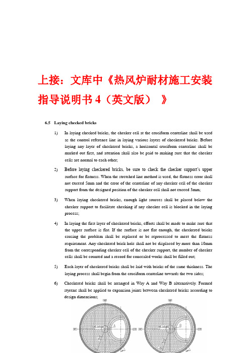
上接:文库中《热风炉耐材施工安装指导说明书4(英文版)》6.5 Laying checked bricks1) In laying checked bricks, the checker cell at the cruciform centerline shall be usedas the control reference line in laying various layers of checkered bricks. Beforelaying any layer of checkered bricks, a horizontal cruciform centerline shall bemarked out first, and attention shall also be paid to making sure that the checkercells are normal to each other;2) Before laying checkered bricks, be sure to check the checker support’s uppersurface for flatness. When the stretched line method is used, the flatness error shallnot exceed 5mm and the error of the centerline of any checker cell of the checkersupport from the designed position of the checker cell shall not exceed 3mm;3) When laying checkered bricks, enough light sources shall be placed below thechecker support to facilitate checking if any checker cell is blocked in the layingprocess;4) In laying the first layer of checkered bricks, efforts shall be made to make sure thatthe upper surface is flat. If the surface is not flat enough, the checkered brickscausing the problem shall be replaced or be reprocessed to meet the flatnessrequirement. Any checkered brick hole shall not be displaced by more than 10mmfrom the corresponding checker cell of the checker support, the number of checkercells shall be counted and a record for concealed works shall be filled out;5) Each layer of checkered bricks shall be laid with bricks of the same thickness. Thelaying process shall begin from the cruciform centerline towards the two sides;6) Checkered bricks shall be arranged in Way A and Way B alternatively. Formedstyrene shall be applied to expansion joints between checkered bricks according todesign dimensions;Figure 6.5-1 Schematic diagram for laying checkered bricks7) There shall be an expansion joint available between any checkered brick and thesurrounding furnace wall, and such expansion joints shall be processed withmachinery in advance in the same order as they are formed and then fixed withwood wedges;8) The method for laying a temperature measuring hole on a silica checkered bricksurface is shown in the following figure:Figure 6.5-2 Schematic diagram 1 for laying a temperature measuring hole on a silica checkeredbrick surfaceCheckered brick SG 6×150Checkered brick SG 6×150Checkered brick SG 64×150Checkered brick SG 64×150Heat storage chamber’ssilica checkered bricktemperature-measuringhole’s centerlineCheckered brick HL 30×180Checkered brick HL 30×180Checkered brick HN 51×180Checkered brick HN 51×180Checkered brick LN 51×180Checkered brick LN 53×180Checkered brick HL 3×180Checkered brick HL 3×180Figure 6.5-3 Schematic diagram 2 for laying a temperature measuring hole on a silica checkeredbrick surface9) In laying checkered bricks, waste rubber sheet shall be used to tightly cover allcheckered bricks to prevent foreign things like falling grout from blocking checker cells;10) In case checkered bricks are laid after the laying of bearing wall reaches a certainheight, all material left on the rubber sheets shall be remove out of the furnace and the rubber sheets shall be removed only after they are properly cleaned. Check if any checker cells of checkered bricks have moved and laying can begin only after no checker cell movement is found;11) After each 5 checkered brick layers are laid, an alignment check shall be given tothe checkered bricks already laid and a flatness check given to the checkered brick surface;12) For the 202nd ~ 207th checkered brick layers, a slant line shall be stricken out tofacilitate rollback laying;Figure 6.5-4 Schematic diagram for bricklaying6.6 Laying the arch top6.6.1 Laying the bearing wall of the arch top’s straight segment1) Check if the elevations of the ledge supports for the 1st and 2nd brick layerscomply with design elevations and if not, use CN-130 pouring material toobtain the desired elevations;2) Lay the straight segment wall (containing the 1st ~ 12th layers) in three timesand after each 4 brick layers are laid, apply δ20mm foamed styrene on theback of the wall body and fill CN-130 pouring material until the designelevation is reached. Then fill the filling of silicon carbide between theelevation of 35.876m and the ledge support for the 2nd brick layer;3) In laying any brick layers above the 12th layer, laying shall be conducted bylayers by starting from the spray painting layer to the working layer;4) When construction proceeds to the place where the straight cylinder segmentof the a rch top and the heat storage chamber’s bearing wall meet,construction shall alternate between the two different areas;6.6.2 Laying the arch top with bricks1) The surface of the topmost brick layer of the arch top’s straight segment wallshall be flat enough and if not, shall be flattened accordingly;2) A rotary shaping plate shall be used in the laying of arch top. There shall be abrick layer marking line on the rotary shaping plate, which can serve as theguiding line in laying each brick layer;Figure 6.6-1 Schematic diagram for controlling the laying of the arch top3) In the laying process, metal hooks shall be used because laid bricks mayslide inwards as the number of layers and slop increase. The metal hooks shall be removed only after the door is closed during construction;4) The laying process shall stop at the 43rd layer to facilitate the installation ofthe wood matrix for the remaining laying process;5) Place a stopper brick in the center of the wood matrix and prearrange other 3rings of bricks once to confirm if the 46th layer of bricks shall be processed.If bricks need to be processed, the thickness of processed bricks shall be no less than 2/3 of the original thickness of the bricks. In processing bricks, care shall be taken in drawing lines on and processing the bricks;6) In laying the heat insulation bricks behind the arch top bricks, the formershall be in close contact with the latter during construction.6.7 Laying the heat storage chamber’s furnace bottom1) The thickness of the heat storage chamber’s furnace bottom is around 160mm andwaste bricks and excess spray paint left over from other laying processes will beused in laying the furnace bottom;2) The 1st layer of the furnace bottom shall be laid after striking out a reference line inthe 90° ~ 270° direction, while the 2nd layer shall be laid with the direction turned by90°;3) After the furnace bottom is laid thoroughly, the steel pipes projecting out of thefurnace bottom’s brick surface sha ll be cut flush with the brick surface;Figure 6.7-1 Schematic diagram for laying the heat storage chamber’s furnace bottom7 Construction of hot-blast piping with refractory7.1 Spray painting of hot-blast piping7.1.1 Construction positionsThe hot-blast piping includes the hot-blast main pipe, hot-blast branch, blastmixing pipe, backflow wind-off pipe, bustle pipe, and flue pipe (refer to Figure7.1 - 1 Schematic diagram for construction positions for hot-blast piping).7.1.2 Key points in construction1) Before spray painting, project all designed centerlines of the pipes(horizontal and vertical) on the tube casings by surveying and use red paintto mark them out properly;2) Weld iron members, used to connect angle steel members, on the two sidesof the horizontal centerlines, placed at intervals of 3m. Then installsupporting angle steel members, and weld iron members and mountsupport members on the tube casing of the vertical face of the angle steelmember;3) Install a fixing center plate on the angle steel support member, making surethat the adjuster bolt is screwed up properly after the cruciform centerlineon the tube casing is aligned with the cruciform center of the hole on thefixing center plate;4) Use the radius rod to check the spray-painting radius after threading astraight steel tube through the hole;5) Spray painting can proceed from bottom to top;6) The spray painting method is the same as 5 Spray painting of the hot-blaststove’s body;7) Be sure to protect all bellows during spray painting. Use cotton yarn tostop off the wire mesh of the bellows, apply a layer of adhesive tape on thecotton yarn, and then use 5-ply board to seal it properly;8) The place, outside the hot-blast branch, adjacent to the flange shall bespray-painted too. The gate valve plate and the gap around it shall besealed tightly before spray painting begins so as to prevent splashes fromstaining the valve plate;9) The blast mixing pipe consists of 3 tube casings with different insidediameters and a variable diameter welded together, the maximum andminimum diameters being ф1200 and ф860 respectively. The pipe shall notbe spray-painted and should be constructed using the method featuringpouring before installation;10) The fume pipe shall be spray-painted only, but not laid. The insidediameters of the various pipes mentioned above upon spray painting mustsatisfy the corresponding diameter required for its laying to proceed;11) The fume pipe shall be spray-painted from the fume port to the end plug;12) Apart from the anchoring members, the fume pipe (ф3500) shall haveadditional ф6 reinforcing bar and ф3.2 wire mesh by design;13) The construction sequence for spray-painting the fume pipe is as follows: Installing steel pipe workbench Tying reinforcing bars Spray-painting tube casingsFigure 7.1-1 Schematic diagram for construction positions of hot-blast pipingPage 10 of 12Figure 7.1-2 Schematic diagram for spray painting construction of hot-blast piping。
热风炉产品说明书

Serie | 2, built-in oven, Stainless steelHBN331E7BIncluded accessories1 x insert grid1 x combination grid 1 x universal panThe built-in oven with special hot air function: you achieve perfect baking and roasting results on up to two levels simultaneously.Hotair creates perfect results thanks to optimal distribution of heat on up to 2 levels simultaneously.Flap door: for especially convenient opening and closing of the oven door.Energy efficiency class A: Best baking results with low energy consumption.Technical DataColor / Material Front : Stainless steel Built-in / Free-standing : Built-in Integrated Cleaning system : No Required niche size for installation (HxWxD) :575-597 x 560-568 x 550Dimensions of the product (mm) : 595 x 595 x 548Dimensions of the packed product (HxWxD) (mm) :670 x 680 x 665Control Panel Material : Metal Door Material : Glass Net weight (kg) : 31.783Usable volume (of cavity) - cavity 1 (l) : 66Cooking method :3D hot air, Defrost, Full width variable grill, Hot air grilling First cavity material : Enamelled Temperature control : mechanical Number of interior lights : 1Approval certificates : CE, KEMA EAN code : 4242002898964Number of cavities (2010/30/EC) : 1Energy efficiency class (2010/30/EC) : A Energy consumption per cycle forced air convection (2010/30/EC) : 0.82Energy efficiency index (2010/30/EC) : 98.8Connection Rating (W) : 2350Current (A) : 13Voltage (V) : 220-240Frequency (Hz) : 50; 60Plug type : fixed connection, no plug'!2E 20A C -i j i j g e !1/3Serie | 2, built-in oven, Stainless steelHBN331E7BThe built-in oven with special hot airfunction: you achieve perfect bakingand roasting results on up to two levelssimultaneously.Key Information-Drop down doorDesign-Retractable control dials-Straight bar handleFeatures-Electronic clock timer-1 interior light-Control panel lock-Cavity inner surface: Enamel-ecoClean® liners NO_FEATURE-4 shelf positions-Full glass inner doorProgrammes/functions-multifunction oven:4 heating methods: 3D hot air, defrost, Hotair grilling, fullwidth variable grillPerformance/technical information-Integral cooling fan-Total connected load electric: 2.35 KW-Appliance dimension (hxwxd): 595 mm x 595 mm x 548 mm-Niche dimension (hxwxd): 575 mm - 597 mm x 560 mm - 568mm x 550 mm-Please refer to the dimensions provided in the installationmanual-Maximum window temperature 50° C-Energy efficiency rating (acc. EU Nr. 65/2014):Energy consumption per cycle in conventional mode: 98.8Energy consumption per cycle in fan-forced convection mode:0.82 kwhNumber of cavities: 1Cavity volume: 66 litreStandard accessories-1 x insert grid, 1 x combination grid, 1 x universal pan2/3Serie | 2, built-in oven, Stainless steelHBN331E7B3/3。
燃油热风炉使用说明书资料

目录一、概述……………………………………………………二、工作原理…………………………………………………三、规格与技术参数…………………………………………四、安装调试与操作使用规程…………………………………五、维护保养与常见故障的排除………………………………六、安全事项…………………………………………………CONTENTSⅠ.I n t r o d u c t i o n……………………………………………Ⅱ.Wo r k i n g P r i n c i p l e s………………………………………Ⅲ. Specifications and technique instruction …………………Ⅳ. Installation adaptation and operation instruction…………Ⅴ. Care and maintenance and remove of common fault………Ⅵ.S a f e i t e m s…………………………………………………一、概述YR系列燃油热风炉是我公司在多年实践的基础上自行研制开发的一种高效节能燃油供热设备,供热能力为1×4.18×106kJ/h~30×4.18×106kJ/h。
热风炉主要由燃料供应装置、供风装置、燃烧装置、燃烧室、混合室及热工控制系统组成。
本产品结构简单、体积小巧、操作安全、维护简便、使用寿命长、供热范围广,温度可随意调配,广泛应用于水泥、化工、冶金等行业中的烘干、焙烧设备提供热源。
二、工作原理燃油热风炉工作原理:燃料由供应装置安全输送到燃烧器,与供风装置送入的空气经燃烧器组织在燃烧室里充分燃烧,产生的高温气体在混合室内与冷空气混合得到符合工艺要求的热烟气。
三、规格与技术参数㈠产品型号YR-nD(Z、G)n=1~30,n=1表示1×4.18×106kJ/h供热能力G表示高温型,供热温度为600~1200℃Z表示中温型,供热温度为300~600℃D表示低温型,供热温度为100~300℃燃油热风炉四、安装调试与操作使用规程㈠安装炉体安装:炉子要安装在牢固的基础上,各连接法兰之间应加石棉绳密封,详见燃油热风炉安装图。
Thermo Scientific 精密小型重力炉辅助热风炉产品说明书

Precision Compact GravityConvection OvensModel No.PR305215G,PR305210G,PR305210GCNPR305225G,PR305220G,PR305220GCNLTM1879X1•8/4/09T able of Contents Introduction (3)Product Overview (3)Safety Information (4)Alert Signals (4)Specifications (5)Power Requirements (5)Overall Dimensions (5)Chamber Dimensions (5)Volume (5)Shipping Weight (5)Performance Characteristics (5)Environmental Operating Conditions (5)Unpacking and Installation (6)Shipping Carton (6)Location (6)Electrical Requirements (6)Installation (7)Operation (8)Start-Up (8)Maintenance (9)Replacement Parts (10)Wiring Diagrams (11)Ordering Procedures (14)Warranty (16)2Introduction4These instructions contain important operating and safety information.The user must carefully read and understand these instructions before using the oven.Y our unit has been designed to optimize function,reliability,safety and ease of use.It is the user’s responsibility to install the oven in conformance with local electrical codes.SafetyInformationWarningWarnings alert you to a possibility of personal injury.CautionCautions alert you to a possibility of damage to the equipment.NoteNotes alert you to pertinent facts and conditions.Hot SurfaceHot surfaces alert you to a possibility of personal injury if you come in contact with a surface during use or for a period of time after use.Alert SignalsSpecificationsUnpacking and InstallationNoteLeave unit disconnected when not in use.6U NPACKING AND I NSTALLATION7NoteIf the equipment is used in specified by the tion provided by the impared.OperationWarningDo not use in the mable or combustible materials or explosive gases.Do not use in the presence of pressurized or sealed containers –fire or explosion may result,causing death or severe injury.WarningDo not heat any substance above a temperature that will cause it to emit toxic fumes;death or severe injury may result.CautionIt is the user’s responsibility to mon-itor oven action when setting and maintaining operating temperature;oven failure may occur with possi-ble property damage and/or injury to personnel.Status LampCon t rol P o w er S wi t c hControl PanelWarningT o avoid electrical short or shock,do not allow any metal object to pro-trude into the space beneath the shelf that serves as the heater shield inside the oven.In addition,do not operate oven with the shield removed.Hot SurfaceAt the higher temperatures,the exte-rior of the oven and particularly the thermometer vent ring on the top become uncomfortably warm to the touch.To avoid burns,do not touch these surfaces.8MaintenanceBecause of their rugged,simple construction,these ovens require very little maintenance.Ordinary cleaning will suf-fice.The bottom shelf that covers the heater can be removed for easy access to the heater area.Clean up any spills as soon as possible to prevent materi-als being baked on surfaces.When the oven is cool,use a mild soap and water to clean surfaces.Rinse thorough-ly and dry.It is best to avoid highly abrasive cleaners that can damage the finish of the interior surfaces and shelves.If the oven fails to heat,there may be several possible causes:•Oven is not receiving electrical power.•Heater is burned out.•Thermostat is malfunctioning.Have a qualified electrical technician determine the cause of the problem and make the necessary repairs.Y our local Thermo Scientific products dealer can provide the service and replacement partsneeded.WarningDisconnect from the power supply prior to maintenance and servicing.NoteMake no attempt to service or repair a Thermo Scientific product under warranty before consulting your Thermo Scientific dealer.After the warranty period,such consultation is still advised,especially when the repair may be technically sophisticat-ed or difficult.If assistance is needed beyond what the distributor can pro-vide,please call Customer Service at 800-553-0039.No merchandiseshould be returned directly to the fac-tory without obtaining a ReturnMaterials Authorization (RMA)num-ber from CustomerService.9Replacement Parts DESCRIPTION PART NUMBER Tension Catch:600-124-00 Handle:560-248-00 Feet:790-225-00 Status Lamp Base:360-233-01 Status Lamp Lens(amber):360-235-00 Power Switch(120V):SWX143 Power Switch(240V):440-292-00 Thermometer Grommet:790-247-00 Thermometer Holder:910-039-00 Control Thermostat:920-412-00 Thermostat Knob:560-265-00Hi-Limit Thermostat:920-413-00 Heaters:PR305215G:340-212-00PR305225G:340-213-00PR305210G,PR305210GCN:340-214-00PR305220G,PR305220GCN:340-215-00 Shelves Kit:PR305215G,PR305210G,PR305210GCN:3510-8QPR305225G,PR305220G,PR305220GCN:3511-8Q10Wiring DiagramsOrdering ProceduresPlease refer to the Specification Plate for the completemodel number,serial number,and series number whenrequesting service,replacement parts or in any corre-spondence concerning this unit.All parts listed herein may be ordered from the ThermoScientific dealer from whom you purchased this unit orcan be obtained promptly from the factory.When serviceor replacement parts are needed we ask that you checkfirst with your dealer.If the dealer cannot handle yourrequest,then contact our Customer Service Departmentat563-556-2241or800-553-0039.Prior to returning any materials,please contact ourCustomer Service Department for a“Return MaterialsAuthorization”number(RMA).Material returned withoutan RMA number will be refused.12One Y ear Limited Warranty This Thermo Scientific product is warranted to be free of defects in materials and workmanship for one(1) year from the first to occur of(i)the date the product is sold by the manufacturer or(ii)the date the product is purchased by the original retail customer(the“Commencement Date”).Except as expressly stated above,the MANUFACTURER MAKES NO OTHER WARRANTY,EXPRESSED OR IMPLIED,WITH RESPECT TO THE PRODUCTS AND EXPRESSL Y DISCLAIMS ANY AND ALL WARRANTIES,INCLUDING BUT NOT LIMITED TO,WARRANTIES OF DESIGN,MERCHANT ABILITY AND FITNESS FOR A PARTICULAR PURPOSE.An authorized representative of the manufacturer must perform all warranty inspections.In the event of a defect covered by the warranty,we shall,as our sole obligation and exclusive remedy,provide free replace-ment parts to remedy the defective product.In addition,for products sold within the continental United States or Canada,the manufacturer shall provide free labor to repair the products with the replacement parts,but only for a period of ninety(90)days from the Commencement Date.The warranty provided hereunder shall be null and void and without further force or effect if there is any(i) repair made to the product by a party other than the manufacturer or its duly authorized service representa-tive,(ii)misuse(including use inconsistent with written operating instructions for the product),mishandling, contamination,overheating,modification or alteration of the product by any customer or third party or(iii)use of replacement parts that are obtained from a party who is not an authorized dealer of Thermo Scientific prod-ucts.Heating elements,because of their susceptibility to overheating and contamination,must be returned to the factory and if,upon inspection,it is concluded that failure is due to factors other than excessive high tempera-ture or contamination,the manufacturer will provide warranty replacement.As a condition to the return of any product,or any constituent part thereof,to the factory,it shall be sent prepaid and a prior written authorization from the manufacturer assigning a Return Materials Number to the product or part shall be obtained.IN NO EVENT SHALL THE MANUFACTURER BE LIABLE TO ANY P ARTY FOR ANY DIRECT,INDIRECT, SPECIAL,INCIDENTAL,OR CONSEQUENTIAL DAMAGES,OR FOR ANY DAMAGES RESULTING FROM LOSS OF USE OR PROFITS,ANTICIPATED OR OTHERWISE,ARISING OUT OF OR IN CONNECTION WITH THE SALE,USE OR PERFORMANCE OF ANY PRODUCTS,WHETHER SUCH CLAIM IS BASED ON CONTRACT,TORT(INCLUDING NEGLIGENCE),ANY THEORY OF STRICT LIABILITY OR REGULATORY ACTION.For the name of the authorized Thermo Scientific product dealer nearest you or any additional information,contact us:2555Kerper Blvd.,Dubuque,Iowa,52004-0797Phone:563-556-2241or1-800-553-0039Fax:563-589-0516Web:13。
- 1、下载文档前请自行甄别文档内容的完整性,平台不提供额外的编辑、内容补充、找答案等附加服务。
- 2、"仅部分预览"的文档,不可在线预览部分如存在完整性等问题,可反馈申请退款(可完整预览的文档不适用该条件!)。
- 3、如文档侵犯您的权益,请联系客服反馈,我们会尽快为您处理(人工客服工作时间:9:00-18:30)。
JDK型空气加热器(热风炉)使用说明书Operation Manual of JDKType Air Heater常州市鼎龙环保设备有限公司常州市鼎马干燥机械有限公司Changzhou Dinglong Environmen Protection Equipment Co., Ltd.Changzhou Dingma Drying Machinery Co., Ltd.二00八年敬告用户Notice抽板式链条炉排调风和清灰系统为一体。
Air regulation and dust cleaning system of drawerpanel-type chain grate is a whole.操纵拉杆每2小时往复拉动清灰后复位至需要的风门开度,切记!!!After reciprocating pull and dust cleaning every 2 hours, please reset the control operating rod, and ensure the properopening of the throttle. DO REMEMBER!!!CONTENT1. 概述Summary (1)2. 结构性能简介Brief Introduction of Structural Performance (2)3. 系统图及说明System Drawing and Explanation (3)4. 点火及启动Ignition and Starting (4)5. 烘炉Heat furnace (5)6. 正常运行Normal Operation (6)7. 链条炉排的运行操作和调节Operation and Adjustment of Chain Grate (7)8. 设备保护Protection of the Equipment (12)9. 系统清灰及清渣Dust Cleaning and Slag Removal for the System (13)10. 停炉Shutdown of the Stove (14)11. 维护和保养Maintenance (15)12. 附:沉降室热风炉的清灰 (17)Appendix: dust cleaning of hot blast stove with settling chamber (17)1.概述SummaryJDK系列空气加热器(也称热风炉)是一种以煤为燃料,以空气为介质的新型高效的换热设备,能连续提供恒温、恒压、无尘的干净热空气,广泛应用于纺织漂染、橡胶涂层的热定型;印铁涂料烘房、金属表面除锈处理后的烘干及油漆烘干,造纸工业的烘干,粮食饲料、谷物鱼粉、烟叶茶叶等的烘干;胶合板、石膏板的成型干燥,木材干燥,化工物料、动植物油脂的喷雾干燥以及工业厂房的采暖等等。
取代目前使用的以蒸汽、油锅炉或电加热空气的方式,减少了热交换环节及相应的热交换设备,具有系统热效率高,设备简化,操作方便,安全可靠,工程投资低等优点。
JDK series air heater (also known as hot blast stove) is new and efficient heat exchange equipment, whose fuel is coal and medium is air. It is able to provide clean hot air continuously, with constant temperature, constant pressure and without dust. This equipment is widely used in the heat setting of textile bleaching and dyeing, and rubber coating; iron printing dryer, drying of de-rusting metal surface and drying of paint, drying of paper industry, as well as foodstuff, forage, cereal, fish meal, tobacco leaves and tea, etc.; dehydration forming of veneer and plasterboards, drying of timber, spray drying of chemical materials, animal and vegetable oil, and the heating of industrial factories, and so on. This product replaces air heating forms such as steam, oil boiler or electricity, and thus reduces heat exchange process and corresponding heat exchange equipment. This product is equipped with lots of advantages, including high thermal efficiency, simpler equipment, convenientoperation, safety and reliability, low engineering investment and so on.2. 结构性能简介Brief Introduction of Structural Performance JDK系列热风炉由燃烧设备(炉体)和换热器两大部件构成,燃料自煤斗进入炉排,通过前拱引燃、人字型后拱反射,在喉口主燃后形成“α”火焰,烟气经过炉膛内折烟墙折射流向炉膛出口。
换热器由多组热交换管束组成,烟气自炉膛出口进入换热器入口,横向冲刷换热器管组,进行高效热交换,自最后一组换热器出口经引风机抽往烟囱,排向大气。
JDK series hot blast stove consists of combustion equipment (furnace body) and heat exchanger. Fuel goes into the grate through coal scuttle, is ignited by face arch and reflected by herringbone rear arch. Combustion at the throat leads to “α” blaze. After the refraction by smoke-turning wall in the hearth, flue gas flows to the exit of hearth. The heat exchanger is made up of many groups of heat-exchange tube bundles. Flue gas comes out of the exit of hearth, goes into the inlet of heat exchanger, transversely scours the tube bundles, and thus carries out efficient heat exchange. After that, flue gas is taken out by induced draft fan from the exit of the last group of heat exchangers, and discharged into the air.在尾部换热器管组入口,由主风机(或加回风补充)供给的空气进入管组,纵向冲刷换热器管束,经转弯风室分别通向各组换热器管束,最后自所需额定温度的管组出口将热风供给用热系统。
Air supply from main air blower (or supplemented by return air) enters the inlet of the tail tube bundles, scours heat-exchange tube bundles lengthwise, and goes through the turning air chamber to all groups of heat-exchange tube bundles. At last, hot blast is supplied to heating using system, from the exit of tube bundles with ratedtemperature.3. 系统图及说明System Drawing and Explanation图例图例::Legend① 电控柜Electrical control cabinet② 点火门Ignition door③ 链条炉排Chain grate stoker④ 鼓风机Air blower⑤ 鼓风机调节门Governing valve of fan⑥ 热电阻/温度指示仪Thermal resistance/temperature indicator⑦ 加热器热风出口热电偶/温度指示仪Thermocouple/ temperature indicator atthe hot-blast outlet of heater⑧ 热交换器进口烟气热电偶/温度指示仪 ⑧Thermocouple/ temperature indicator at the hot-blast inlet of heat exchanger ⑨ 热风出口 Hot-blast outlet ⑩ 主风机调节门 Governing valve of main air blower ⑪ 用回风时补充空气调节门 Governing valve of air supplement by air return ⑫ 引风机调节门 Governing valve of induced draft fan ⑬ 引风机Induced draft fan⑭ 冷风进口Inlet of cold blast⑮ 清灰孔Dust cleaning hole⑯ 热交换器下部清灰门Soot door at the bottom of heat exchanger ⑰ 热交换器下部清灰门Soot door at the bottom of heat exchanger ⑱ 热交换器Heat exchanger ⑲ 主风机Main air blower4. 点火及启动Ignition and Starting点火前的准备Preparation before ignition4.1点火前检查各部件是否完好无损?Before ignition, check whether or not every part is complete and in good condition.4.2煤闸门升降是否灵活?Check whether or not the coal gate rises and falls flexibly.4.3链条炉排运转是否正常?Check whether or not the chain grate operates normally.4.4鼓、引风机风门开启是否灵活?Check whether or not the throttles of air blower and induced draft fan can be opened flexibly.4.5检查炉排变速箱、上煤机、出渣机、炉排后滚筒处各润滑点是否注满了规定的润滑油类?Check whether or not lubricating points are filled with stated lubricants, including grate gear-box, coal loader, slag extractor and rollers behind the grate.4.6查看各风机冷却水是否通畅?Check whether or not the cooling water of air blowers is smooth.4.7系统烟道、风道是否严密?配有除尘系统的,除尘器卸灰门闸是否密封,开放灵活?Check whether or not system flue and air duct is compact. In the case of dedusting system, check whether or not the ash discharging gate is airproof and flexible to open.4.8配有湿式除尘系统的,循环水是否通畅?As for wet dedusting system, check whether or not the circulating water is smooth.4.9检查电气设备是否正常,指示正确?Check whether or not the electrical equipment is normal. Is the indication correct?4.10以上准备工作就绪后,开始点火启动。