vhdl课程设计(电子钟+闹铃)
数字钟的设计
一、系统功能概述
(一)、系统实现的功能:
1、具有“时”、“分”、“秒”的十进制数字显示(小时从00 ~ 23)。
2、具有手动校时、校分、校秒的功能。
3、有定时和闹钟功能,能够在设定的时间发出闹铃声。
4、能进行整点报时。从59分50秒起,每隔2秒发一次低音“嘟”的信号,连续5次,
最后一次为高音“嘀”的信号。
(二)、各项设计指标:
1、显示部分采用的6个LED显示器,从高位至低位分别显示时、分、秒。
2、有一个设置调闹钟定时时间、正常时间的按钮,选择调的对象。
3、有三个按钮分别调时、分、秒的时间。
4、有一个按钮用作开启/关闭闹铃。
5、另外需要两个时钟信号来给系统提供脉冲信号,使时钟和闹钟正常工作,分别为1Hz、
1kHz的脉冲。
二、系统组成以及系统各部分的设计
1、系统结构描述//要求:系统(或顶层文件)结构描述,各个模块(或子程序)的功能描述;(一)系统的顶层文件:
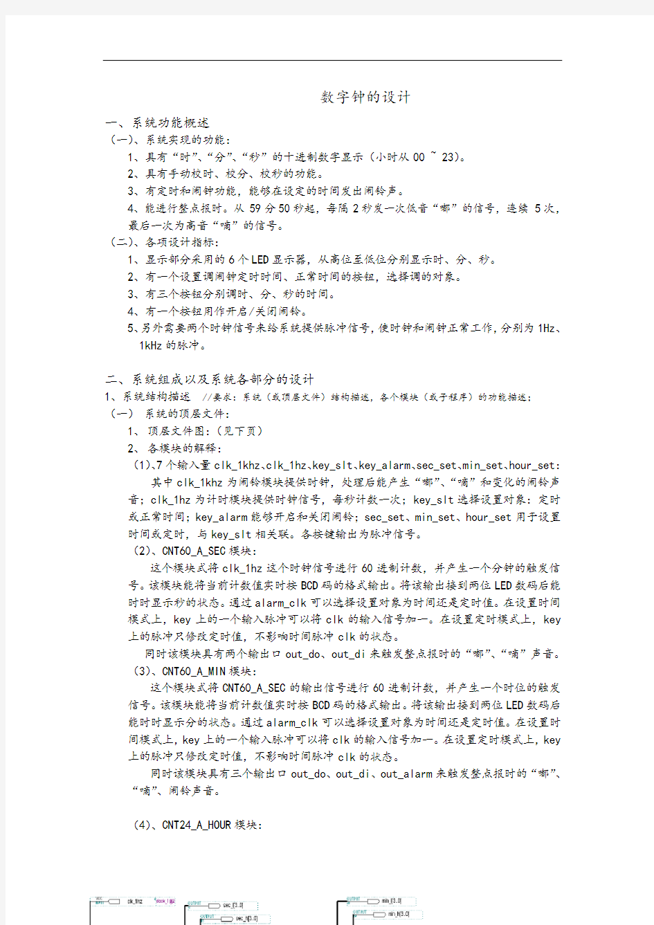
1、顶层文件图:(见下页)
2、各模块的解释:
(1)、7个输入量clk_1khz、clk_1hz、key_slt、key_alarm、sec_set、min_set、hour_set:其中clk_1khz为闹铃模块提供时钟,处理后能产生“嘟”、“嘀”和变化的闹铃声音;clk_1hz为计时模块提供时钟信号,每秒计数一次;key_slt选择设置对象:定时或正常时间;key_alarm能够开启和关闭闹铃;sec_set、min_set、hour_set用于设置时间或定时,与key_slt相关联。各按键输出为脉冲信号。
(2)、CNT60_A_SEC模块:
这个模块式将clk_1hz这个时钟信号进行60进制计数,并产生一个分钟的触发信号。该模块能将当前计数值实时按BCD码的格式输出。将该输出接到两位LED数码后能时时显示秒的状态。通过alarm_clk可以选择设置对象为时间还是定时值。在设置时间模式上,key上的一个输入脉冲可以将clk的输入信号加一。在设置定时模式上,key 上的脉冲只修改定时值,不影响时间脉冲clk的状态。
同时该模块具有两个输出口out_do、out_di来触发整点报时的“嘟”、“嘀”声音。
(3)、CNT60_A_MIN模块:
这个模块式将CNT60_A_SEC的输出信号进行60进制计数,并产生一个时位的触发信号。该模块能将当前计数值实时按BCD码的格式输出。将该输出接到两位LED数码后能时时显示分的状态。通过alarm_clk可以选择设置对象为时间还是定时值。在设置时间模式上,key上的一个输入脉冲可以将clk的输入信号加一。在设置定时模式上,key 上的脉冲只修改定时值,不影响时间脉冲clk的状态。
同时该模块具有三个输出口out_do、out_di、out_alarm来触发整点报时的“嘟”、“嘀”、闹铃声音。
(4)、CNT24_A_HOUR模块:
这个模块式将CNT60_A_MIN的输出信号做24进制计数。该模块能将当前计数值实时按BCD码的格式输出。将该输出接到两位LED数码后能时时显示时的状态。通过alarm_clk可以选择设置对象为时间还是定时值。在设置时间模式上,key上的一个输入脉冲可以将clk的输入信号加一。在设置定时模式上,key上的脉冲只修改定时值,不影响时间脉冲clk的状态。
同时该模块具有一个输出口out_alarm来触发整点报时的闹铃声音。
(5)、PWM_OUT模块:
该模块为PWM产生模块,通过EN可开启和关闭PWM输出。模块根据CLK信号二分频产生的高低音,并组合,能输出三种声音状态——“嘟”、“嘀”、闹铃。而该三种声音要被秒、分、时的输出触发才能输出PWM。
(二)系统各个模块的VHDL程序:
(1)、CNT60_A_SEC模块:
程序源代码如下:
library ieee;
use ieee.std_logic_1164.all;
use ieee.std_logic_unsigned.all;
entityt60_a_sec is
port(
clk,clr,enb: in std_logic;--clk:时钟输入信号,clr:清零端,enb:使能端 key: in std_logic; --输入按键脉冲,调整闹铃定时或时间
alarm_clk: in std_logic;--1:alarm 0:clk --设置模式选择:闹铃调节模式、时间调节模式
qout_sl: out std_logic_vector(3 downto 0); --显示输出秒的低位
qout_sh: out std_logic_vector(3 downto 0);--显示输出秒的高位
co: out std_logic; --进位输出,触发分计数模块
out_do: out std_logic;--在整点报时中输出“嘟”触发信号
out_di: out std_logic --在整点报时中输出“嘀”触发信号
);
end;
architecture a oft60_a_sec is
signal qout2_l:std_logic_vector(3 downto 0);
signal qout2_h:std_logic_vector(3 downto 0);
signal alarm_l:std_logic_vector(3 downto 0);
signal alarm_h:std_logic_vector(3 downto 0);
signal clk1,clk2,tclk,aclk,ac_slt: std_logic;
begin
process(alarm_clk) --当该端口输入一个脉冲时,修改设置模式:时间调整或闹铃模式切换
begin
if alarm_clk'event and alarm_clk='1' then
if ac_slt='0' then--如果为定时模式,将改为闹铃模式
ac_slt<='1';
else
ac_slt<='0';
end if;
end if;
end process;
process(key,clk,ac_slt)--根据设置模式,处理key上的脉冲信号
begin
if ac_slt='0' then --时间调整模式
aclk<='0';
if clk='1' and key='1' then --clk=1则tclk<=0,通过挖洞方式添加一个脉冲
tclk<='0';
elsif clk='0' and key='1' then --clk=0,则tclk<=1,产生一个高电平,添加一脉冲
tclk<='1';
else
tclk<=clk;
end if;
elsif ac_slt='1' then --闹铃调整模式
tclk<=clk;
aclk<=key; --key上的脉冲直接修改闹铃定时值
end if;
end process;
process(tclk,clr,enb) --60进制计数,个位、十位放在两个临时变量中,表示秒的状态
begin
if clr='1' then--clearing works at the state of high voltage
qout2_l<="0000";
qout2_h<="0000";
elsif tclk'event and tclk='1' then
if enb='1' then--enable works at high voltage
if qout2_l="1001" and qout2_h="0101" then
qout2_l<="0000";--a full mode is completed and a carryout is generated
qout2_h<="0000";
elsif qout2_l="1001" then
qout2_l<="0000";
qout2_h<=qout2_h+1;
else
qout2_l<=qout2_l+1;-- in process of counting
end if;
end if;
end if;
end process;
process(aclk,clr,enb)--修改闹铃的定时值
begin
if clr='1' then--clearing works at the state of high voltage
alarm_l<="0000";
alarm_h<="0000";
elsif aclk'event and aclk='1' then
if enb='1' then--enable works at high voltage
if alarm_l="1001" and alarm_h="0101" then
alarm_l<="0000";--a full mode is completed and a carryout is generated
alarm_h<="0000";
elsif alarm_l="0101" then
alarm_l<="0000";
alarm_h<=alarm_h+1;
else
alarm_l<=alarm_l+1;-- in process of counting
end if;
end if;
end if;
end process;
process(qout2_l,qout2_h,alarm_l,alarm_h,alarm_clk)-- 产生进位,显示时间或闹铃定时值
begin
if qout2_l="0000" and qout2_h="0000" then
co<='1';
else
co<='0';
end if;
if ac_slt='0' then -- 显示时间
qout_sl<=qout2_l;
qout_sh<=qout2_h;
else -- 显示定时值
qout_sh<=alarm_h;
qout_sl<=alarm_l;
end if;
end process;
process(qout2_l,qout2_h) -- 根据秒的状态输出“嘟”、“嘀”触发信号
begin
if qout2_h="0101" then
if qout2_l="0000" then
out_do<='1';
elsif qout2_l="0010" then
out_do<='1';
elsif qout2_l="0100" then
out_do<='1';
elsif qout2_l="0110" then
out_do<='1';
elsif qout2_l="1000" then
out_do<='1';
else
out_do<='0';
end if;
elsif qout2_h="0000" then
if qout2_l="0000" then
out_di<='1';
out_do<='0';
else
out_di<='0';
end if;
else
out_do<='0';
out_di<='0';
end if;
end process;
end;
(2)、CNT60_A_MIN模块:
library ieee;
use ieee.std_logic_1164.all;
use ieee.std_logic_unsigned.all;
entityt60_a_min is
port(
clk,clr,enb: in std_logic; --clk:时钟输入信号,clr:清零端,enb:使能端 key: in std_logic; --输入按键脉冲,调整闹铃定时或时间
alarm_clk: in std_logic; --1:alarm 0:clk --设置模式选择:闹铃调节模式、时间调节模式
qout_ml: out std_logic_vector(3 downto 0); --显示输出分的低位
qout_mh: out std_logic_vector(3 downto 0); --显示输出分的高位
co: out std_logic; --进位输出,触发时计数模块
out_alarm:out std_logic;--闹铃触发信号,时间到后输出高电平触发闹铃out_do,out_di: out std_logic--在整点报时中输出“嘟”“嘀”触发信号);
end;
architecture a oft60_a_min is
signal qout2_l:std_logic_vector(3 downto 0);
signal qout2_h:std_logic_vector(3 downto 0);
signal alarm_l:std_logic_vector(3 downto 0);
signal alarm_h:std_logic_vector(3 downto 0);
signal clk1,clk2,tclk,aclk,ac_slt: std_logic;
begin
process(alarm_clk) --当该端口输入一个脉冲时,修改设置模式:时间调整或闹铃模式切换
begin
if alarm_clk'event and alarm_clk='1' then
if ac_slt='0' then--如果为定时模式,将改为闹铃模式
ac_slt<='1';
else
ac_slt<='0';
end if;
end if;
end process;
process(key,clk,ac_slt) --根据设置模式,处理key上的脉冲信号
begin
if ac_slt='0' then --时间调整模式
aclk<='0';
if clk='1' and key='1' then--clk=1则tclk<=0,通过挖洞方式添加一个脉冲
tclk<='0';
elsif clk='0' and key='1' then--clk=0,则tclk<=1,产生一个高电平,添加一脉冲
tclk<='1';
else
tclk<=clk;
end if;
elsif ac_slt='1' then --闹铃调整模式
tclk<=clk;
aclk<=key; --key上的脉冲直接修改闹铃定时值
end if;
end process;
process(tclk,clr,enb) --60进制计数,个位、十位放在两个临时变量中,表示分的状态
begin