索尼KLV-46X300A液晶电视维修手册
索尼电视屏幕维修
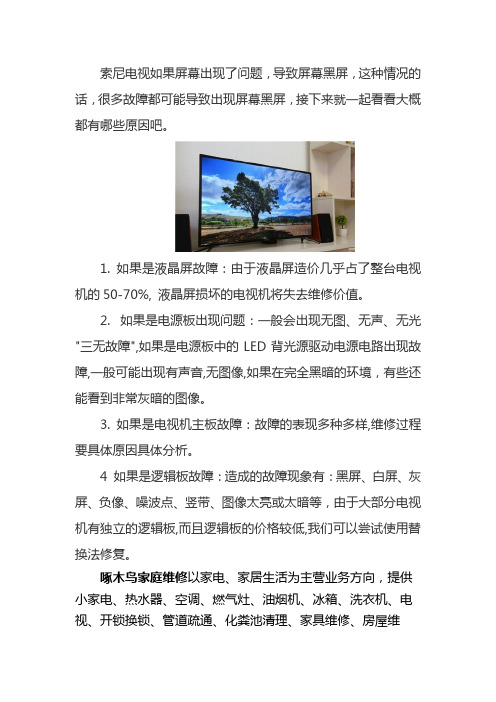
索尼电视如果屏幕出现了问题,导致屏幕黑屏,这种情况的话,很多故障都可能导致出现屏幕黑屏,接下来就一起看看大概都有哪些原因吧。
1. 如果是液晶屏故障:由于液晶屏造价几乎占了整台电视机的50-70%, 液晶屏损坏的电视机将失去维修价值。
2. 如果是电源板出现问题:一般会出现无图、无声、无光"三无故障",如果是电源板中的LED背光源驱动电源电路出现故障,一般可能出现有声音,无图像,如果在完全黑暗的环境,有些还能看到非常灰暗的图像。
3. 如果是电视机主板故障:故障的表现多种多样,维修过程要具体原因具体分析。
4 如果是逻辑板故障:造成的故障现象有:黑屏、白屏、灰屏、负像、噪波点、竖带、图像太亮或太暗等,由于大部分电视机有独立的逻辑板,而且逻辑板的价格较低,我们可以尝试使用替换法修复。
啄木鸟家庭维修以家电、家居生活为主营业务方向,提供小家电、热水器、空调、燃气灶、油烟机、冰箱、洗衣机、电视、开锁换锁、管道疏通、化粪池清理、家具维修、房屋维
修、水电维修、家电拆装等保养维修服务。
液晶电视维修手册
*以LA40A750为例
8
I. LCD TV内部结构(IP电源)
T – CON 板
CN1
CNI803 CN103 CNI806 CN801
CN6105_FFC CN6001_LCD
背光驱动 (BL Driver)
IP电源板 (IP Board)
CNI801 CNI802
CN1001
主板 (Main Board)
2%
yes
⑤
FRCM测试故障?
no no
yes
⑥
T-Con板不 良
5% 更换LVDS线后 是否有故障?
FBE测试故障?
yes
no
no
更换T-Con板后 是否有故障?
LVDS线不良 yes
77%
yes
液晶屏不良
16
III-3. 间歇性无图像
非故障检查项目: 检查是否电源线接触不良? 故障检查项目:
故障发生时待机 灯是否点亮?
24
注意:具体型号接口定义以维修手册为准
附. 排线接口检测方法
接口④------屏幕亮度(Dimming)控制(部分型号Dimming控制端在主板电源接口中)
PIN NAME 1 SW_inverter 2 Ana_dimming 3 PWM_dimming 4 GND 5 GND
功能定义:
-- SW_inverter -- Ana_dimming -- PWM_dimming 控制屏幕逆变器 约5V 屏幕明暗控制 屏幕明暗控制PWM方式, 占空比 40%~90%
no no
3%
yes
⑥
FBE测试故障?
18% 更换LVDS线后 是否有故障?
yes
电视维修手册
电视维修手册第一章:电视故障诊断与维修方法一、电视无法开机当电视无法开机时,首先需要检查以下几个方面:1. 电源插头是否插紧:请确保电源插头已经完全插入电视的电源插座,并且插紧。
2. 电源线是否损坏:检查电源线是否有明显的破损或者断裂情况,如有需要更换新的电源线。
3. 电源开关是否打开:确保电源开关已经打开,有些电视可能有独立的电源开关。
如果以上检查都没有问题,但电视仍然无法开机,可能是以下原因之一:1. 电视主板故障:电视主板是电视的核心部件,如果主板损坏,可能导致电视无法正常开机。
此时建议联系专业维修人员进行维修或更换主板。
2. 电源供应故障:电视的电源供应部分可能出现故障,导致电视无法正常供电。
此时建议联系专业维修人员进行维修或更换电源供应部件。
二、电视无法接收信号或画面不清晰当电视无法接收信号或者画面不清晰时,可以按照以下步骤进行故障排除:1. 检查天线连接:确保电视天线线缆连接牢固,没有松动或者断裂。
如果有需要,可以重新连接天线线缆并确保信号良好。
2. 调整天线方向:有时候电视信号不好是由于天线方向不正确导致的。
可以尝试调整天线的方向,找到最佳的信号接收位置。
3. 检查信号源设备:如果电视无法接收到信号,可能是信号源设备的问题。
可以检查信号源设备(如有线电视盒、DVD播放器等)是否正常工作,以及连接线是否完好。
如果以上步骤都没有解决问题,可能是以下原因之一:1. 电视调谐器故障:电视调谐器是接收信号的重要部件,如果调谐器出现故障,可能导致无法接收信号或者画面不清晰。
此时建议联系专业维修人员进行维修或更换调谐器。
2. 信号源设备故障:如果信号源设备本身出现故障,可能导致电视无法正常接收信号。
此时建议检查信号源设备的工作状态,或者联系专业维修人员进行维修。
第二章:常见电视故障及解决方法一、电视画面出现噪点当电视画面出现噪点时,可以尝试以下方法进行故障排除:1. 调整信号源设备:有时候噪点是由于信号源设备输出信号不稳定导致的。
索尼电视维修
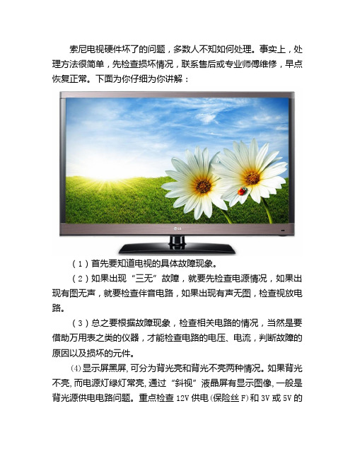
索尼电视硬件坏了的问题,多数人不知如何处理。
事实上,处理方法很简单,先检查损坏情况,联系售后或专业师傅维修,早点恢复正常。
下面为你仔细为你讲解:(1)首先要知道电视的具体故障现象。
(2)如果出现“三无”故障,就要先检查电源情况,如果出现有图无声,就要检查伴音电路,如果出现有声无图,检查视放电路。
(3)总之要根据故障现象,检查相关电路的情况,当然是要借助万用表之类的仪器,才能检查电路的电压、电流,判断故障的原因以及损坏的元件。
(4)显示屏黑屏,可分为背光亮和背光不亮两种情况。
如果背光不亮,而电源灯绿灯常亮,通过“斜视”液晶屏有显示图像,一般是背光源供电电路问题。
重点检查12V供电(保险丝F)和3V或5V的开关电压是否正常。
修理的思路(电源保险丝——开关控制管——电源管理IC——电源开关管——DA转换电路(储能电感,整流管)——LC升压电路(升压变压器,升压电容)——耦合电容——灯管。
如果背光亮,通过“斜视”观察液晶屏无显示图像,则可判断为液晶屏驱动故障。
此时首先应检查DC-DC转换器供电是否正常,如果DC-DC转换电路输出电压异常,则检修DC-DC转换器,如果正常,则应重点检查时序控制电路的输出信号,如使能信号(EN),锁存信号(LP)和移位信号(CP)等。
如果以上信号异常,则检查Timing Controller芯片是否正常工作,是否有引脚虚焊或芯片损坏。
如果时序控制电路的输出信号正常,DC-DC供电正常,则问题一般出现在行、列驱动芯片上。
行、列驱动在Source-PCB上,显示屏厂家将其和液晶屏一起捆绑销售,因此无论是Panel损坏或这种芯片损坏,没有配套芯片和专业设备无法维修。
(5)屏幕亮线,亮带或者是暗线。
这种一般是液晶屏的故障。
液晶显示器需要用电压控制产生灰阶,而薄膜晶体管的作用相当于一个开关,其主要决定LCD source driver 上来的电压是否充到这个像素点,以及这个像素点需要充到多高的电压,以此来控制该点液晶分子转向,进而控制显示相应的灰阶。
索尼LCD电视产品维修与回收指南说明书
Dismantling information for use by professional recyclersLCD TV9-888-723-41Conditions of Use:(1) Please use this information only for the purpose of repair and recycling of Sony products. Using this information for any purpose other than the purpose described foregoing is forbidden.(2) Do not copy, replicate, reproduce, alter, translate, transmit, sell, lease, or distribute this information in whole or in partwithout the prior written permission of the author.Revision of Information:This information may be changed or updated at any time without any prior notice. Please confirm that this information is up-Sony Home Entertainment & Sound Products Inc.Model :KDL-32W6600KDL-32W6603KDL-32W6605ORIGINAL MANUAL ISSUE DATE:2021.02MODEL LISTMODEL REMOTE DESTINATIONKDL-32W6600RMT-TX300E CEIKDL-32W6603RMT-TX300E CEIKDL-32W6605RMT-TX300E CEITOOLS &EQUIPMENTS 1 LIST OF ITEMS TO BRING1.Screwdriver(e.g. #2 Phillips Screwdriver)2.Multimeter3.ESD Wrist Straps4.Metal Washer(Flat)or Coin(for remove Rear Cover)5.Ruler (for remove Rear Cover)2 OPTIONAL EQUIPMENT1.Screwdriver (e.g. #0 Phillips Screwdriver)2.Parts Tray for loose screws and small items3.FlashlightFor Surface Mounted Parts/Connectors;Hot-Air Type soldering Iron is needed.Thickness: approx. 1.5mm Diameter: 20~25mm(wrap in tape (L=50mm))Plastic or Metal Ruler(In case of Metal ruler, wrap in tape (L=50mm) for prevent scratches)DISSASSEMBLY51STAND, ASSY•Place the TV set facing downwards on a stable, level surface before disassembly and assembly of parts.• and shaded parts are critical for safety. Replace only with part number specified.• Parts contain confidential information. Strictly follow the instruction whenever the components are repaired and/or replaced.(*) Parts are not stocked since they are seldom required for routine service. Some delays should be anticipated when ordering these components.Picture provided in this section might have slight difference from the actual sets. Lines that indicate parts are shown in blue in the illustration.The reference number beside the part description indicates the disassembly sequence. Remove screws before disassembly. Unplug connectors before disassembly!3-1. KDL-32WE6*3-1-1. Disassembly, Exploded ViewREAR COVERLOUDSPEAKER237P-MODLABEL, SVC HOTLINE VTBRACKET, SIDE (FRE)4SWITCH UNIT5CARDWIRELESS LANUNIVERSAL SIL-TU11BLM BOARD1215LK1 BOARD 1498SHEET, THERMAL (BM)1LABEL, UNDER TERMINAL136BRACKET SWITCHHKT-E MOUNT10GUIDE, LIGHT LOUDSPEAKER7BEZELPANEL,ORNAMENT (MZT)16DISASSEMBLY, EXPLODED VIEWS AND OTHER PARTS8381828485REF. NO PART NO.DESCRIPTIONREMARKS811-912-039-11FLEXIBLE FLAT CABLE 30P CN8501(BLM)-SOURCE BOARD (1) KDL-32WE613/615/610 (CEI/UKA)811-912-036-11FLEXIBLE FLAT CABLE 30P CN8501(BLM)-SOURCE BOARD (1) KDL-32WE613 (RU3)821-849-990-11FLEXIBLE FLAT CABLE 40P CN9601(BLM)-CN9901(LK1) (1) 83-not applicable-FLEXIBLE FLAT CABLE 51P --not service part for Europe region -841-912-024-11FLEXIBLE FLAT CABLE 5P CN9500(BLM)-J1(DNUR-SY3) (1) KDL-32WE613/615/610 (CEI/UKA)841-912-033-11FLEXIBLE FLAT CABLE 5P CN9500(BLM)-J1(DNUR-SY3) (1) KDL-32WE613 (RU3)851-910-805-95HARNESS ASSYCN9602(BLM)-CN100(HKT)-CN1(3KEY)/CN4001(LK1)-SP (1)HARNESS/CABLE!REF. NO PART NO.DESCRIPTIONREMARKS1-not applicable-LABEL, UNDER TERMINAL (MZT)-not service part for Europe region -2-not applicable-LABEL, SERVICE HOTLINE VT -not service part for Europe region -3A-2181-666-A REAR COVER (2S MZT) ASSY KDL-32WE613/610 (CEI/UKA)34-596-529-31REAR COVER (2S MZT) A KDL-32WE613 (RU3)3A-2182-773-A REAR COVER (2S MZT) A KDL-32WE61544-595-950-31BRACKET, SIDE (FRE)KDL-32WE613/61044-595-950-41BRACKET, SIDE (FRE)KDL-32WE61551-474-647-12SWITCH UNIT (3M-P)64-595-952-01BRACKET, SWITCH (MZT)71-859-227-11LOUDSPEAKER 81-458-959-12CARD, WIRELESS LAN 9A-2178-585-A HKT-E MOUNT104-689-347-01GUIDE, LIGHT (MZT) A118-594-328-00UNIVERSAL SIL-TU SUT-DE251ZP KDL-32WE613 (CEI/UKA)118-594-328-10UNIVERSAL SIL-TU SUT-DE251ZP KDL-32WE613 (RU3)118-594-326-00UNIVERSAL SIL-TU SUT-CE251ZP KDL-32WE615118-594-301-30UNIVERSAL SIL-TU SUT-RE243ZP KDL-32WE610 12A-2180-699-B COMPL SVC BLM_KM_AEP_WXGA 134-549-186-02SHEET, THERMAL(BM)14A-2179-427-A SPRO MODULE LK1_M32_M4015A-2180-817-A P-MOD (IS7S320HNO0101)(SERVICE 164-596-261-01PANEL, ORNAMENT (MZT)STAND514-596-028-31STAND BASE (2S MZT) A KDL-32WE613/615/610 (CEI/UKA)514-596-028-01STAND BASE (2S MZT) AKDL-32WE613 (RU3)PARTS LISTMT(2スライド 7MT(2 T-CONなし?Matsunaga, Toshiya (SHES), 2020/12/03! !PART NO.DESCRIPTION REMARKS1-493-332-11AC ADAPTOR(60W)KDL-32WE613/6101-493-000-51AC ADAPTOR (85W)KDL-32WE6154-262-708-04CLAMPER, CABLE1-846-420-11CORD SET, POWER-SUPPLY KDL-32WE613/615/610 (CEI) 1-846-421-11CORD SET, POWER-SUPPLY KDL-32WE613 (UKA)1-846-093-52CORD SET, POWER-SUPPLY KDL-32WE613 (RU3)A-2180-523-A DIGITAL AUDIO ADAPTOR ASSY1-493-314-11REMOTE COMMANDER(RMT-TX300E)4-588-089-02BAG, SCREW ASSY (TQS)!PARTS LIST!REF. NO PART NO.DESCRIPTIONREMARKS12A-2180-699-B COMPL SVC BLM_KM_AEP_WXGA 14A-2179-427-A SPRO MODULE LK1_M32_M4015A-2180-817-AP-MOD (IS7S320HNO0101)(SERVICEPrinted Circuit Board,incl.capacitors Liquid Crystal DisplayPrinted Circuit Board,incl.capacitors PART NO.DESCRIPTION REMARKS 1-493-332-11AC ADAPTOR(60W)KDL-32WE613/610 1-493-000-51AC ADAPTOR (85W)KDL-32WE6151-846-420-11CORD SET, POWER-SUPPLYKDL-32WE613/615/610 (CEI)!External Power Supply CableSET PART LISTOther PartsPARTS LIST109-888-723-41English© 2021.02Sony Home Entertainment & Sound Products Inc.。
索尼KLV-32V200A、40V200A、46V200A液晶显示器维修手册(英文版)(可编辑)

索尼KLV-32V200A、40V200A、46V200A液晶显示器维修手册(英文版)MODIFICATION HISTORYMODEL NAME : KLV-32/40/46V200ASERVICE MANUALPARTS No. : 9-834-116-02* Blue characters are linking Ver. DATA CONTENTS1.0 2006.07 Issued1.1 2007.03 Correction SEC.4 EXPLODED P. 4-8, 4-9, 4-10, 4-12, 4-13, 4-14, 4-15AD6570234986BC6048C237EAB20B143372A38C3C2892F4CFD0B74BA760A75EAEB 7F5000B75EA3B9DKLV-32V200A/40V200A/46V200AChina ModelSERVICE MANUALWAX2 CHASSISSPECIFICATIONSDisplay UnitPanel SystemPower Requirements: LCD Liquid Crystal Display Panel 220 V AC, 50 HzTV SystemScreen Size: I, D/K, B/G, M KLV-46V200A: 46 inchesColor System KLV-40V200A: 40 inches PAL, PAL60, SECAM, NTSC 4.43, NTSC 3.58 KLV-32V200A: 32 inchesAntennaDisplay Resolution: 75 ohm external terminal 1,366 pixels horizontal × 768 lines verticalPower Consumption: Channel Coverage Indicated on the rear of the TV.B/GDimensions w × h × d: VHF: E2 to E12 / UHF: E21 to E69 / KLV-46V200A:CATV: S01 to S03, S1 to S41 Approx. 1120 × 805 ×334 mm with stand I Approx. 1120 × 755 × 116 mm without standUHF: B21 to B68 / CATV: S01 to S03, S1 to S41 KLV-40V200A:D/K Approx. 988 × 716 × 334 mm with stand VHF: C1 to C12, R1 to R12 / UHF: C13 to C57, R21 to Approx. 988 × 664 × 103 mm without standR60 / KLV-32V200A:CATV: S01 to S03, S1 to S41, Z1 to Z39 Approx. 792 × 593 × 219 mm with stand M Approx. 792 × 546 × 99 mm without standVHF: A2 to A13/ UHF: A14 to A79 /Weight: CATV: A-8 to A-2, A to W+4, W+6 to W+84 KLV-46V200A: Approx.34 kg with stand Approx. 29 kg without stand KLV-40V200A:Approx. 27 kg with stand Approx. 22 kg without stand KLV-32V200A: Approx. 17 kg with stand Approx. 15 kg without standLCD Color TVAD6570234986BC6048C237EAB20B143372A38C3C2892F4CFD0B74BA760A75EAEB7F5000B75EA3B9DTerminalsS VIDEO 1/2: S S VIDEO 4-pin mini DIN: S Y: 1.0 Vp-p, 75 ohms unbalanced, sync negative C: 0.286 Vp-p Burst signal, 75ohms VIDEO IN 1/2/3:VIDEO: 1 Vp-p, 75 ohms unbalanced, sync negative AUDIO: 500 mV rms Impedance: 47 kilohms.HD/DVD IN 1/2:Y, PB/CB, PR/CR Component Video: Y:1.0 Vp-p, 75 ohms unbalanced, sync negative PB/CB:0.7 Vp-p, 75 ohms PR/CR:0.7 Vp-p, 75 ohms Signal format: 480i, 576i, 480p, 576p, 720p, 1080iAUDIO: 500 mV rms Impedance: 47 kilohmsVIDEO OUT: VIDEO : 1 Vp-p, 75 ohms unbalanced, sync negative AUDIO: More than 1 Vrms at the imum volume setting Variable More than 500 mV rms FixedHDMI IN Video:1080i, 720p, 576p, 576i, 480p, 480i Audio:Two channel Linear PCM32, 44.1 and 48kHz, 16, 20 and 24bits,PC: D-sub 15-pin, analogue RGB, 0.7 Vp-p, 75 ohms, positive See the PC input signal Reference chart on page 32 Audio: Stereo minijack, 0.5 Vrms, 1 kilohmHeadphones i Stereo minijackKLV-32/40/46V200A CH 2AD6570234986BC6048C237EAB20B143372A38C3C2892F4CFD0B74BA760A75EAEB7F5000B75EA3B9DTABLE OF CONTENTSSefety Check Out/Leakage Test4 3-4-15. G1 Board Schematic Diagram Caution Handling5 KLV-32V200A 3-22Lead free information. 5 3-4-16. G2 Board Schematic DiagramSELF DIAGNOSTIC6 KLV-40/46V200A 3-233-4-17. H1 Board Schematic Diagram 3-241. DISASSEMBLY1-1 3-4-18. H2 Board Schematic Diagram1-1. REAR COVER REMOVAL1-1 EXCEPT-KLV-46V200A. 3-251 KLV-32V2OOA 1-1 3-4-19. H4 Board Schematic Diagram 3-262 KLV-40/46V2OOA. 1-1 3-4-20. H46 Board Schematic Diagram1-2. VESA BRACKET ASSEMBLY REMOVAL. 1-2 KLV-46V200A 3-271-3. H1 BOARD REMOVAL. 1-3 3-4-21. TUG Board Schematic Diagram 3-28 1-4. H2 BOARD EXCEPT KLV-46V200A / 3-5. VOLTAGE MEASUREMENTH46 BOARD KLV-46V200A REMOVAL 1-3 AND WAVEFORMS3-291-5. G1 AND G2 BOARDS REMOVAL. 1-4 3-6. PRINTED WIRING BOARDS3-30 1-6. AG BOARD REMOVAL 1-4 3-7. SEMICONDUCTORS 3-371-7. TUG BOARD REMOVAL. 1-51-8. DTT SHIELD REMOVAL. 1-5 4. EXPLODED VIEWS..4-11-9. B BOARD REMOVAL 1-6 4-1. KLV-32V200A4-21-10. AC INLET REMOVAL 1-7 4-1-1. REAR COVER ASSY AND STAND ASSY4-2 1-11. SPEAKER AND H4 BOARD REMOVAL1-7 4-1-2. H1 AND H2 BOARD 4-3 1-12-1.LCD PANEL REMOVAL KLV-32V200A. 1-8 4-1-3. AG, B AND TUG BOARDS. 4-41-12-2. TOP FRAME REMOVAL KLV-40/46V200A 1-9 4-1-4. G1 BOARD AND AC INLET4-54-1-5. H4 BOARD AND SPEAKER4-62. SERVICE ADJUSTMENTS2-1 4-1-6. BEZEL ASSY AND LCD PANEL 4-72-1. How to enter Service Mode 2-1 4-2. KLV-40/46V200A 4-82-2. Signal Level Adjustment2-1 4-2-1. REAR COVER ASSY AND STAND ASSY4-82-3. Gamma Adjustment. 2-3 4-2-2. H1 BOARD AND H2 H46 BOARDS4-9 2-4. White Balance Adjustment. 2-3 4-2-3. AG, B AND TUG BOARDS4-10 2-5. Panel Replacement2-5 4-2-4. G2 BOARD AND AC INLET 4-112-6. Board Replacement. 2-5 4-2-5. H4 BOARD AND SPEAKER 4-124-2-6. BEZEL ASSY AND LCD PANEL. 4-133. BLOCK DIAGRAMS.3-1 4-3. PACKING MATERIALS KLV-32V200A4-143-1. BLOCK DIAGRAMS 3-1 4-4. PACKING MATERIALS KLV-40/46V200A4-15 3-1-1. TUG BLOCK DIAGRAM3-13-1-2. G1 BLOCK DIAGRAM KLV-32V200A 3-2 5. ELECTRICAL PARTS LIST..5-1 3-1-3. G2 BLOCK DIAGRAM KLV-40/46V200A 3-33-1-4. B, H1 AND H4 BLOCK DIAGRAMS 3-43-1-5. AG AND H2/H46 BLOCK DIAGRAMS3-53-2. FRAME DIAGRAM3-63-3. CIRCUIT BOARDS LOCATION3-73-4. SCHEMATIC DIAGRAMS INFORMATION. 3-73-4-1. AG Board-0013-83-4-2. AG Board-002. 3-93-4-3. B Board-001. 3-103-4-4. B Board-002. 3-113-4-5. B Board-003 3-123-4-6. B Board-004 3-133-4-7. B Board-005. 3-143-4-8. B Board-006. 3-153-4-9. B Board-007. 3-163-4-10. B Board-008. 3-173-4-11. B Board-009 3-183-4-12. B Board-010 3-193-4-13. B Board-011. 3-203-4-14. B Board-012. 3-21KLV-32/40/46V200A CH 3AD6570234986BC6048C237EAB20B143372A38C3C2892F4CFD0B74BA760A75EAEB 7F5000B75EA3B9DUSE CAUTION WHEN HANDLING THE LCD PANEL LEAKAGE TEST The AC leakage from any exposed metal part to earth ground andfrom all exposed metal parts to any exposed metal part having a When installing the LCD panel, be sure you are grounded by usinga wrist band. return to chassis, must not exceed 0.5 mA 500 microamperes.When istalling the LCD panel on the wall, the LCD panel must be Leakage current can be measured by any one of three methods. secured using the 4 mounting holes on the rear cover.1. A commercial leakage tester, such as the Simpson 229 or RCA WT-540A. Follow the manufacturers’ instructions to use these1. do not press on the panel or frame edge to avoid the risk of instructions.electric shock.2. A battery-operated AC milliampmeter. The Data Precision 245 2. do not scratch or press on the panel with any sharp objects. digital multimeter is suitable for this job.3. do not leave the module in high temperatures or in areas of high 3. Measuring the voltage drop across a resistor by means of a humidity for an extended period of time.VOM or battery-operated AC voltmeter. The “limit” indica-4. do not expose the LCD panel to direct sunlight.tion is 0.75 V, so analog meters must have an accurate low5. avoid contact with water. It may cause a short circuit within the voltage scale. The Simpson’s 250 and Sanwa SH-63TRD are module.examples of passive VOMs that are suitable. Nearly all bat-6. disconnect the AC adapter when replacing the backlight CCFLtery-operated digital multimeters that have a 2 VAC range areor inverter circuit.suitable see Figure A.High voltage occurs at the inverter circuit at 650Vrms7. always clean the LCD panel with a soft cloth material.8. use cere when handling the wires or connectors of the inverter To Exposed Metalcircuit. Damaging the wires may cause a short. Parts on Set9. protect the panel from ESD to avoid damaging the electronic circuit C-MOS.ACSAFETY CHECK-OUT0.15 ?F 1.5 kVoltmeter0.75 VAfter correcting the original service problem, perform the following safety checks before releasing the set to the customer:1. Check the area of your repair for unsoldered or poorly soldered Earth Groundconnections. Check the entire board surface for solder splashes and bridges.Fig. A. Using an AC voltmeter to check AC leakage.2. Check the interboard wiring to ensure that no wires are“pinched” or contact high-wattage resistors.3. Check that all control knobs, shields, covers, ground straps, and mounting hardware have been replaced. Be absolutely certain WARNING!!that you have replaced all the insulators.4. Look for unauthorized replacement parts, particularlySAFETY-RELATED COMPONENT WARNING!!transistors, that were installed during a previous repair. Point COMPONENTS IDENTIFIED BY SHADING AND MARK !them out to the customer and recommend their replacement.ON THE SCHEMATIC DIAGRAMS, EXPLODED VIEWS5. Look for parts which, though functioning, show obvious signs of AND IN THE PARTS LIST ARE CRITICAL FOR SAFEdeterioration. Point them out to the customer and recommend OPERATION. REPLACE THESE COMPONENTS WITHtheir replacement.SONY PARTS WHOSE PART NUMBERS APPEAR AS6Check the line cords for cracks and abrasion. Recommend the SHOWN IN THIS MANUAL OR IN SUPPLEMENTSreplacement of any such line cord to the customer.PUBLISHED BY SONY. CIRCUIT ADJUSTMENTS THAT7. Check the antenna terminals, metal trim, “metallized” knobs,ARE CRITICAL FOR SAFE OPERATION AREscrews, and all other exposed metal parts for AC leakage. Check IDENTIFIED IN THIS MANUAL. FOLLOW THESEleakage as described below.PROCEDURES WHENEVER CRITICAL COMPONENTSARE REPLACED OR IMPROPER OPERATION ISSUSPECTED.KLV-32/40/46V200A CH 4 44AD6570234986BC6048C237EAB20B143372A38C3C2892F4CFD0B74BA760A75EAEB 7F5000B75EA3B9DCAUTIONexample 1The circuit boards used in these models have been processed using Lead Free Solder. The boards are identified by the LF logo located close to the board designation e.g. H1 etc [ see example ]. The servicing of these boards requires special precautions to be taken asoutlined below.It is strongly recommended to use Lead Free Solder material in order to guarantee optimal quality of new solder joints.Lead Free Solder is available under the following part numbers : Part number Diameter Remarks7-m 640-005-19 0K .3m 0.25g7m -640-005-20 0K .4 m 0.50gm7m -640-005-21 0K .5 0.50g7m -640-005-22 0K .6 m 0.25g7m -640-005-23 0K .8 m 1.00g7m -640-005-24 1K .0 m 1.00g7m -640-005-25 1K .2 m 1.00g7m -640-005-26 1K .6 m 1.00gDue to the higher melting point of Lead Free Solder the soldering iron tip temperature needs to be set to 370 degreescentigrade. This requires soldering equipment capable of accurate temperature control coupled with a good heat recoverycharacteristics.For more information on the use of Lead Free Solder, please refer to ////0>.KLV-32/40/46V200A CH 5AD6570234986BC6048C237EAB20B143372A38C3C2892F4CFD0B74BA760A75EAEB 7F5000B75EA3B9DSELF DIAGNOSTIC FUNCTIONControl ButtonsMENUTV/VIDEO VOLUME CHANNEL POWERPIC OFF/TIMER STANDBY POWERDescription of LED IndictorsLED LED Type Description* Light is green when the TV set is onPOWER LED Red/Green LED * Functions as failure indicator* Blinks green in aging modeTIMER LED Red LED Lights when timer is setLights when power saving setting is set toPIC OFF LED Green LEDpicture off See Instruction ManualKLV-32/40/46V200A CH6AD6570234986BC6048C237EAB20B143372A38C3C2892F4CFD0B74BA760A75EAEB 7F5000B75EA3B9DLED ControlTIMER LED/ STANDBYSTATUS POWER LED REMARKSPICTURE OFF LED LEDPower off using the power switch orremote controlNOTE: Standbystate does not exist in this model;Power Off Off Off Offhowever, the microcomputer doesenter into sleep mode.Power On Lights Green Off Off Microcomputer working normally.Failure causes are classified by theFailure Blinks Red Off Offnumber of time the red light blinks.Aging mode is classified by a blinkingAging Blinks Green Off Offgreen light.Picture Off Lights Green Lights Green No display black screen. OffWhen SLEEP TIMER is set duringLights OrangeOffLights Green power on.SLEEP TIMERWhen SLEEP TIMER is set inLights Green OffLights Green Picture Off mode.When ON TIMER is set and power isOffLights Orangeoff.OffWhen ON TIMER is set and power isON TIMERLights Orange OffLights Green on.When ON TIMER is set in Picture OffOffLights GreenLights Green mode.Off Off Lights RedPC STANDBYPC STANDBY/Lights OrangeOff Lights RedTIMER ONThe units in this manual contain a self-diagnostic function. If an error occurs, the POWER LED will automatically begin to flash. The number of times the LED flashes translates to a probable source of the problem. A definition of the POWER LED flash indicators is listed in t he instruction manual for the user’s knowledge and reference. If an error symptom is difficult to reproduced use the Remote Commander to display the record that is stored at the internal NVM to specify the cause of the failure.Diagnostic Test IndicatorsWhen an error occurs, the POWER LED will flash a set number of times to indicate the possible cause of the problem. If there is more than one error, the LED will identify the first of the problem areas. If the errors occur simultaneously, the one that corresponds to the fewest flashes is identified first. Results for all of the following diagnostic items are displayed on screen. No error has occurred if the screen displays a “0”.LEDERROR ERROR DESCRIPTIONCODE1 Supply Voltage Trouble Panel 5V UNReg 10.5V2 DE5V Voltage Trouble FE5V DCALERT23Voltage Trouble D3.3V/D2.5V/D1.8V. DCALERT14 Backlight Trouble5 Main Supply Voltage Trouble 17.5V.DET6 Speaker Applied Voltage Trouble7 Monitor an Increase in Inside-Temperature esp. on the panel side8Trident IC TroubleKLV-32/40/46V200A CH 7AD6570234986BC6048C237EAB20B143372A38C3C2892F4CFD0B74BA760A75EAEB 7F5000B75EA3B9DSECTION 1DISASSEMBLY1-1. REAR COVER REMOVAL1 KLV-32V200A3Two Screws +BVTP 3 X 12Two Screws2+PSW M6 X 161Twelve Screws4 Lift to remove Rear Cover+BVTP2 4 X 162 KLV-40/46V200AKLV-46V200A2 Two screwsKLV-40V200A +BVTP2 4X163 One screw3 One screw +BVTP2 4X166 Five screws +BVTP2 4X16 +PSW M3X5 1 Four screws7 Five screws +PSW M6X162 Two screws +BVTP 3X123 Two screws+BVTP2 4X16 +BVTP2 4X16KLV-46V200A5 Three screws +BVTP2 4X168 Lift to remove Rear Cover Assy5 One screw +BVTP2 4X16Two screws4 +BVTP2 4X16KLV-46V200AKLV-40V200A4 Two screws +BVTP2 4X165 Two screws +BVTP2 4X16KLV-46V200AKLV-32/40/46V200A CH 1-1AD6570234986BC6048C237EAB20B143372A38C3C2892F4CFD0B74BA760A75EAEB 7F5000B75EA3B9D1-2. VESA BRACKET ASSEMBLY REMOVAL1 Three screws4 Vesa assy bracket L3 Two screws +PSW M5X16 +BVTP M4X165 Two screws +BVTP2 M4X162 Stand assy6 Vesa assy bracket RKLV-40V200A/46V200A1 Three screws3 One screw +PSW M5X16 +PSW M4X166 Vesa assy bracket R4 Vesa assy bracket L5 One screw2 Stand assy +PSW M4X16KLV-32V200AKLV-32/40/46V200A CH 1-2AD6570234986BC6048C237EAB20B143372A38C3C2892F4CFD0B74BA760A75EAEB 7F5000B75EA3B9D1-3. H1 BOARD REMOVAL1Disconnect CN101Lift tabs to remove board43 3 Two Screws +BVTP24 X 12KLV-32V200A/40V200ATwo Screws +BVTP2 4 X 16H1 boardKLV-46V200AMulti Button Assy21-4. H2 BOARD Except KLV-46V200A/H46 BOARD KLV-46V200A REMOVAL Two screws3 +BVTP 3 X 12 TYPE2 IT-3 Except KLV-40V200A2 H2 board Except KLV-46V200AH46 board KLV-46V200A4 Side jack holder L KLV-40V200A/46V200AOne Connector CN201 KLV-46V200A1Side jack holder M KLV-32V200ASide terminal assy5KLV-32/40/46V200A CH 1-3AD6570234986BC6048C237EAB20B143372A38C3C2892F4CFD0B74BA760A75EAEB 7F5000B75EA3B9D1-5. G1 AND G2 BOARDS REMOVAL2 Two screwsKLV-32V200A +BVTP 3X121 Four screws +PSW 3SG1 Two screws +PSW M3X55 G1 assy bracket3 G1 board2 G2 board4 Two screws +PSW M3X53 Bracket, G2KLV-40V200A/46V200A1-6. AG BOARD REMOVAL2 Two screws +BVTP3 X 12 Type2 IT-31 6 Connectors CN9502, CN9501, CN7503, CN9001, CN7000, CN97023 Four screws +PSW 3SG4 AG boardKLV-32/40/46V200A CH 1-4AD6570234986BC6048C237EAB20B143372A38C3C2892F4CFD0B74BA760A75EAEB 7F5000B75EA3B9D1-7. TUG BOARD REMOVAL3 One screw + PSW 3SG2 Three screws + BVTP3 X 12 TYPE2 IT-24 TUG board1 3 Connectors CN3802, CN3903, CN39041-8. DTT SHIELD REMOVAL1 Two screws2 One screw +PSW M3X5 +PSW M3X53 Two screws HEX4 Top DTT ShieldKLV-32/40/46V200A CH 1-5AD6570234986BC6048C237EAB20B143372A38C3C2892F4CFD0B74BA760A75EAEB 7F5000B75EA3B9D1-9. B BOARD REMOVAL2 One screw +PSW M3X53 Lead wire with connector LVDS5 Two screws +PSW 3SG4 Two screws 1 Connectors +BVST 3 X 8 CN1004, CN1003, CN1007,CN7009, CN1002, CN1700,CN5000, CN1001, CN7008,CN10086 B board9 Bracket assy A,TU7 Two screws +PSW M3X58 DTT shield assy LOWERKLV-32/40/46V200A CH 1-6AD6570234986BC6048C237EAB20B143372A38C3C2892F4CFD0B74BA760A75EAEB 7F5000B75EA3B9D1-10. AC INLET REMOVAL5 Cover under4 Two screws1 One screw +BVTP2 4 X 16 +PSW M4X86 Two screws +BVTP2 4 X 162 Two screws +KTT 3X10⁷ Four screws +PSW M5X83 AC Inlet4 Two screws +BVTP2 4 X 165 Under cover2 Two screws +KTT3 X 108 Bottombracket assy6 Two screws +PSW 4 X 8 3 AC inlet1 One screw7 Bottom bracket +PSW M4X8KLV-40V200A/46V200AKLV-32V200A1-11. SPEAKER AND H4 BOARD REMOVAL2 Loudspeaker2 Loudspeaker3 Loudspeaker1 H4 boardKLV-46V200A3 LoudspeakerKLV-32V200A/40V200AKLV-32/40/46V200A CH 1-7AD6570234986BC6048C237EAB20B143372A38C3C2892F4CFD0B74BA760A75EAEB 7F5000B75EA3B9D1-12-1. LCD PANEL REMOVAL KLV-32V200A1 Two screws +PSW M4X82 Frame top assy5 One screw +BVTP2 4X166 One screw +PSW M3X53 One screw +PSW M3X54 G support7 Harnesswith connector LVDS8 LCD panelBezel assyKLV-32/40/46V200A CH 1-8AD6570234986BC6048C237EAB20B143372A38C3C2892F4CFD0B74BA760A75EAEB 7F5000B75EA3B9D1-12-2. TOP FRAME REMOVAL KLV-40/46V200A4 One screw +PSW 5X85 Two screws +BVTP2 4X121 One screw2 Two screws +BVTP2 4X12+PSW 5X86 Top frame 403 Top frame 40KLV-40V200A4 One screw +PSW 5X85 One screw +BVTP2 4X121 One screw +PSW 5X82 One screw +BVTP2 4X126 Top frame 403 Top frame 40KLV-32/40/46V200A CH 1-9EAD6570234986BC6048C237EAB20B143372A38C3C2892F4CFD0B74BA760A75EAEB 7F5000B75EA3B9DSECTION 2 SERVICE ADJUSTMENTS2-1. How to enter Service Mode 2-2. Signal Level AdjustmentService adjustments to this model can be performed using the supplied 2-2-1. Set up of AD calibration 1 adjustment forremote Commander RM-GA005. terrestrial analog.The following adjustments are done via ECS.1. Turn on the power to the TV set and en。
液晶电视维修手册(pdf 84页)

主板 (小信号处理+逻辑驱动)
第二节 主板组件速判速修
1、LS08机芯(TDA15063 + GM1501方案)
派生系列 W***F8系列 W***F8P系列 TD***F8系列 18系列 18P系列 20系列
代表机型 CHD-W260F8、CHD-W270F8、CHD-W320F8、CHD-W370F8 CHD-W270F8P、CHD-W320F8P、CHD-W370F8P CHD-TD270F8、CHD-TD320F8、CHD-TD370F8 LT2618、LT3218、LT3718、LT4018、LT4219B LT3718P、LT4018P LT5520
2、LP09机芯(PW328 + PW2300方案)
派生系列 19/20系列 19P/19H/66系列 99系列 33系列
代表机型 LT4219、LT4619、LT3718H、LT4720H LT4719H、LT4219P、LT4619P、LT4266、 LT4219H LT4099、LT4299、LT4699 LT4233
LS08机芯技改方案
1. F8/18系列音量关小,有交流噪音。 解决方案:将主板功放电路位号为RA8在主板背面(15K)的电阻改为 10K或8.2K。改后若整体音量变小,请对TDA15063进行升级,以提高 TDA15063输出的伴音信号的幅度。
2. 37〞~42〞F8/18 系列电源板出现噪音 解决方案:取消自制GP03开关电源中U810、L810、D818。
目录
一、液晶电视的结构及各组件控制关系: 二、长虹液晶电视主板组件的快速识别: 三、OEM产品的快速识别和判定: 四、屏上组件的识别和判定: 五、二合一电源组件组件的识别和判定: 六、技术资料的查询和替换:
液晶电视维修手册共33页文档

END
•
26、我们像鹰一样,生来就是自由的 ,但是 为了生 存,我 们不得 不为自 己编织 一个笼 子,然 后把自 己关在 里面。 ——博时 间再长 ,也还 是没有 制约力 的。— —爱·科 克
•
28、好法律是由坏风俗创造出来的。 ——马 克罗维 乌斯
•
29、在一切能够接受法律支配的人类 的状态 中,哪 里没有 法律, 那里就 没有自 由。— —洛克
•
30、风俗可以造就法律,也可以废除 法律。 ——塞·约翰逊
液晶电视维修手册
16、业余生活要有意义,不要越轨。——华盛顿 17、一个人即使已登上顶峰,也仍要自强不息。——罗素·贝克 18、最大的挑战和突破在于用人,而用人最大的突破在于信任人。——马云 19、自己活着,就是为了使别人过得更美好。——雷锋 20、要掌握书,莫被书掌握;要为生而读,莫为读而生。——布尔沃
- 1、下载文档前请自行甄别文档内容的完整性,平台不提供额外的编辑、内容补充、找答案等附加服务。
- 2、"仅部分预览"的文档,不可在线预览部分如存在完整性等问题,可反馈申请退款(可完整预览的文档不适用该条件!)。
- 3、如文档侵犯您的权益,请联系客服反馈,我们会尽快为您处理(人工客服工作时间:9:00-18:30)。
MODIFICATION HISTORYMODEL NAME : KL V-46/52X300A, 46/52W380ASERVICE MANUALP ARTS No. : 9-834-177-02* Blue characters are linking.Ver.DAT A CONTENTS1.02007.09Issued1.12008.06Addition of KLV-46W380A/52W380A Models.(P. 2 to P. 3, P. 6, P. 1-13, P. 1-19, P. 4-1, P. 5-15, P. 5-22, P. 5-31)SERVICE MANUALFIX2 CHASSISKLV-46X300A/52X300A/46W380A/52W380ALCD Colour TVChina ModelRM-SA013KLV-46X300A/52X300ASPECIFICATIONS* Specified standby power is reached after the TV finishes necessary internal processes. ** The values of dimensions and mass are approximate.CAUTIONThese servicing instructions are for use by qualified service personnel only.To reduce the risk of electric shock, do not perform any servicing other than that contained in the operating instructions unless you are qualified to do so.WARNING!!An isolation transformer should be used during any service to avoid possible shock hazard, because of live chassis.The chassis of this receiver is directly connected to the ac power line.! SAFETY-RELATED COMPONENTWARNING!!Replace all components with Sony parts whose part numbers appear as shown in this manual or in supplements published by Sony.WARNINGS AND CAUTIONSSAFETY-RELATED COMPONENTWARNINGIt is essential that all critical parts be replaced only with the part number specified in the electrical parts list to prevent electric shock, fire, or other hazard.NOTE:Do not modify the original design without obtainingwritten permission from the manufacturer or you will void the original parts and labor guarantee.USE CAUTION WHEN HANDLING THE LCD PANEL When repairing the LCD panel, be sure you are grounded by using a wrist band.When repairing the LCD panel on the wall, the LCD panel must be secured using the 4 mounting holes on the rear cover.1)Do not press on the panel or frame edge to avoid the risk ofelectric shock.2)Do not scratch or press on the panel with any sharp objects.3)Do not leave the module in high temperatures or in areas ofhigh humidity for an extended period of time.4)Do not expose the LCD panel to direct sunlight.5)Avoid contact with water. It may cause a short circuit withinthe module.6)Disconnect the AC power when replacing the backlight (CCFL)or inverter circuit.(High voltage occurs at the inverter circuit at 650Vrms.)7)Always clean the LCD panel with a soft cloth material.8)Use care when handling the wires or connectors of the invertercircuit. Damaging the wires may cause a short.9)Protect the panel from ESD to avoid damaging the electroniccircuit (C-MOS).SAFETY CHECK-OUTAfter correcting the original service problem, perform the following safety checks before releasing the set to the customer: 1.Check the area of your repair for unsoldered or poorlysoldered connections. Check the entire board surface forsolder splashes and bridges.2.Check the interboard wiring to ensure that no wires are“pinched” or touching high-wattage resistors.3.Check that all control knobs, shields, covers, ground straps,and mounting hardware have been replaced. Be absolutely certain that you have replaced all the insulators.4.Look for unauthorized replacement parts, particularlytransistors, that were installed during a previous repair. Point them out to the customer and recommend their replacement.5.Look for parts which, though functioning, show obvioussigns of deterioration. Point them out to the customer andrecommend their replacement.6.Check the line cords for cracks and abrasion. Recommendthe replacement of any such line cord to the customer.7.Check the antenna terminals, metal trim, “metallized”knobs, screws, and all other exposed metal parts for ACleakage. Check leakage as described below.Leakage TestThe AC leakage from any exposed metal part to earth ground and from all exposed metal parts to any exposed metal part having a return to chassis, must not exceed 0.5 mA (500 microamperes).Leakage current can be measured by any one of three methods.1. A commercial leakage tester, such as the Simpson 229 orRCA WT-540A. Follow the manufacturers’ instructions touse these instructions.2. A battery-operated AC milliampmeter. The Data Precision245 digital multimeter is suitable for this job.3.Measuring the voltage drop across a resistor by means of aVOM or battery-operated AC voltmeter. The “limit”indication is 0.75 V, so analog meters must have an accurate low voltage scale.The Simpson’s 250 and Sanwa SH-63TRD are examples of passive VOMs that are suitable. Nearly all battery-operated digital multimeters that have a 2 V AC range are suitable (see Figure A).How to Find a Good Earth GroundA cold-water pipe is a guaranteed earth ground; the cover-plate retaining screw on most AC outlet boxes is also at earth ground. If the retaining screw is to be used as your earth ground, verify that it is at ground by measuring the resistance between it and a cold-water pipe with an ohmmeter. The reading should be zero ohms.If a cold-water pipe is not accessible, connect a 60- to 100-watt trouble- light (not a neon lamp) between the hot side of the receptacle and the retaining screw. Try both slots, if necessary, to locate the hot side on the line; the lamp should light at normal brilliance if the screw is at ground potential (see Figure B).FigureA. Using an AC voltmeter to check AC leakage. Figure B. Checking for earth ground.SELF DIAGNOSIS FUNCTIONThe units in this manual contain a self-diagnostic function. If an error occurs, the STANDBY LED will automatically begin to flash.The number of times the LED flashes translates to a probable source of the problem.A definition of the STANDBY LED flash indicators is listed in the instruction manual for the user’s knowledge and reference.If an error symptom cannot be reproduced, the remote commander can be used to review the failure occurrence data stored in memory to reveal past problems and how often these problems occur.1-1.DIAGNOSTIC TEST INDICATORSWhen an error occurs, the STANDBY LED will flash a set number of times to indicate the possible cause of the problem.If there is more than one error, the LED will identify the first of the problem areas.Result for all of the following diagnostic items are displayed on screen.If the screen displays a “0”, no error has occurred .Number of times STANDY LEDMonitoring Items Diagnostic Item Description(Red) flashes (Screen Display)2 times POW OVP Main Power Over Voltage Protection 3 times POW ERR1Power Error 5 times T_CON T_CON Error6 times BACKLITE Back Light Error (Panel Inverter)7 times TEMP ERR Temperature Abnormal Detection8 times AUD PROT Audio Abnormal Detection9 times FAN_ERR FAN Error (Not Detected. Display Only)13 timesBALANCERPanel Balancer Error1-2.DISPLAY OF STANDBY LED FLASH COUNT1-3.STOPPING THE STANDBY FLASHTurn off the power switch on the TV main unit or unplug the power cord from the outlet to stop the STANDBY lamp from flashing.< KLV-46/52X300A >< KLV-46/52W380A >1-4.SELF-DIAGNOSTIC SCREEN DISPLAYFor errors with symptoms such as “power sometimes shuts off” or “screen sometimes goes out” that cannot be confirmed, it is possible to bring up past occurrences of failure for confirmation on the screen:1-4-1.To Bring Up Screen TestIn standby mode, press buttons on the remote commander sequentially in rapid succession as shown below:Since the diagnostic results displayed on the screen are not automatically cleared, always check the self-diagnostic screen After you have completed the repairs, clear the result display to “0”.1-5.Quitting Self-diagnostic screenTo quit the entire self-diagnostic screen, turn off the power switch on the remote commander or the main unit.TORS"[ SELF-DIAGNOSTIC SCREEN DISPLAY ]TABLE OF CONTENTSSAFETY CHECK-OUT (5)SELF DIAGNOSIS FUNCTION (6)1.DISASSEMBLY...............................................1-11-1.KLV-46X300A.......................................................1-1 1-1-1.REAR COVER ASSY REMOVAL................1-1 1-1-2.STAND ASSY AND ARM ASSYREMOVAL......................................................1-1 1-1-3.H1 BOARD REMOVAL.................................1-2 1-1-4.HW2 BOARD REMOVAL.............................1-2 1-1-5.DF1 BOARD AND GF1 BOARDREMOVAL......................................................1-3 1-1-6.AG BOARD AND FB2 BOARDREMOVAL......................................................1-3 1-1-7.TUG BOARD REMOVAL..............................1-4 1-1-8.SPEAKER AND FAN REMOVAL................1-4 1-1-9.UB1 BOARD REMOVAL..............................1-5 1-1-10.H3 BOARD AND H4 BOARD ANDAC INLET REMOVAL...................................1-5 1-1-11.LCD PANEL AND FRONT CABINET ASSYREMOVAL......................................................1-6 1-2.KLV-52X300A.......................................................1-7 1-2-1.REAR COVER ASSY REMOVAL................1-7 1-2-2.STAND ASSY AND ARM ASSYREMOVAL......................................................1-7 1-2-3.H1 BOARD REMOVAL.................................1-8 1-2-4.HW2 BOARD REMOVAL.............................1-8 1-2-5.DF2, DF3 AND GF1 BOARDS REMOVAL.1-9 1-2-6.AG AND FB2 BOARDS REMOVAL............1-9 1-2-7.TUG BOARD REMOVAL............................1-10 1-2-8.SPEAKER AND FAN REMOVAL..............1-10 1-2-9.UB1 BOARD REMOVAL............................1-11 1-2-10.H3 BOARD AND H4 BOARD ANDAC INLET REMOVAL.................................1-11 1-2-11.LCD PANEL AND FRONT CABINET ASSYREMOVAL....................................................1-12 1-3.KLV-46W380A....................................................1-13 1-3-1.REAR COVER ASSY REMOVAL..............1-13 1-3-2.STAND ASSY AND ARM ASSYREMOVAL....................................................1-13 1-3-3.HW1 BOARD REMOVAL...........................1-14 1-3-4.HW2 BOARD REMOVAL...........................1-14 1-3-5.DF2, DF3 AND GF1 BOARDSREMOVAL....................................................1-15 1-3-6.AG AND FB2 BOARDS REMOVAL..........1-15 1-3-7.TUG BOARD REMOVAL............................1-16 1-3-8.CHASSIS BRACKET AND STAYREMOVAL....................................................1-16 1-3-9.FAN AND SPEAKER REMOVAL..............1-17 1-3-10.UB2 BOARD REMOVAL............................1-17 1-3-11.LCD PANEL AND HW3 BOARDREMOVAL....................................................1-18 1-4.KLV-52W380A....................................................1-19 1-4-1.REAR COVER ASSY REMOVAL..............1-19 1-4-2.STAND ASSY AND ARM ASSYREMOVAL....................................................1-191-4-3.HW1 BOARD REMOVAL...........................1-20 1-4-4.HW2 BOARD REMOVAL...........................1-20 1-4-5.DF4, DF5 AND GF2 BOARDSREMOVAL....................................................1-21 1-4-6.FB TOP SHIELD REMOVAL......................1-21 1-4-7.AG AND FB2 BOARDS REMOVAL..........1-22 1-4-8.TUG BOARD REMOVAL............................1-22 1-4-9.UB2 BOARD REMOVAL............................1-23 1-4-10.CHASSIS BRACKET AND STAYREMOVAL....................................................1-23 1-4-11.SPEAKER REMOVAL.................................1-24 1-4-12.LCD PANEL AND HW3 BOARDREMOVAL....................................................1-242.SERVICE MODE ADJUSTMENT...................2-12-1.Go to TV standby condition...................................2-1 2-2.Entering Service Mode...........................................2-1 2-3.Change Setting Data for TV...................................2-2 2-4.Write data for TVM................................................2-3 2-5.Entering BEM service menu..................................2-4 2-6.Change Setting Data for BEM...............................2-5 2-7.Write data for BEM................................................2-6 2-8.CH Model...............................................................2-7 2-9.How to change shipping condition........................2-83.TROUBLE SHOOTING...................................3-13-1.No Power (Flow Chart_B).....................................3-2 3-2.Set Reboots.............................................................3-3 3-3.SELF DIAGNOSIS................................................3-4 3-3-1.Flow Chart_C...................................................3-5 3-3-2.POWER OVP (RED 2 Times blink)...............3-6 3-3-3.POWER ERROR (RED 3 Times blink)..........3-6 3-3-4.T-CON ERROR (RED 5 Times blink)............3-7 3-3-5.BACK LIGHT ERROR(RED 6 Times blink)........................................3-7 3-3-6.TEMP ERROR (RED 7 Times blink).............3-8 3-3-7.AUDIO ERROR (RED 8 Times blink)...........3-8 3-3-8.DTAU ERROR (RED 10 Times blink)...........3-9 3-3-9.BALANCER ERROR(RED 13 Times blink)....................................3-10 MUNICATION ERROR.............................3-11 3-5.AUDIO PROBLEM (Flow Chart_D)..................3-12 3-6.VIDEO PROBLEM (Flow Chart_E)...................3-134.DIAGRAMS.....................................................4-14-1.CIRCUIT BOARDS LOCATION.........................4-1(1)KLV-46X300A................................................4-1(2)KLV-52X300A................................................4-1(3)KLV-46W380A................................................4-1(4)KLV-52W380A................................................4-15.EXPLODED VIEWS........................................5-15-1.KLV-46X300A.......................................................5-2 5-1-1.REAR COVER ASSY.....................................5-2 5-1-2.ARM ASSY AND STAND ASSY ANDHW2 BOARD..................................................5-3 5-1-3.CHASSIS-1......................................................5-4 5-1-4.CHASSIS-2......................................................5-5 5-1-5.FAN AND SPEAKER.....................................5-6 5-1-6.FRONT CABINET ASSY ANDLCD PANEL....................................................5-7 5-1-7.CONNECTOR ASSY......................................5-8 5-2.KLV-52X300A.......................................................5-9 5-2-1.REAR COVER ASSY.....................................5-9 5-2-2.ARM ASSY AND STAND ASSY ANDHW2 BOARD................................................5-10 5-2-3.CHASSIS-1....................................................5-11 5-2-4.CHASSIS-2....................................................5-12 5-2-5.FAN AND SPEAKER...................................5-13 5-2-6.FRONT CABINET AND LCD PANEL.......5-14 5-3.KLV-46W380A....................................................5-15 5-3-1.REAR COVER ASSY...................................5-15 5-3-2.ARM ASSY AND STAND ASSY ANDHW2 BOARD................................................5-16 5-3-3.CHASSIS-1....................................................5-17 5-3-4.CHASSIS-2....................................................5-18 5-3-5.SPEAKER AND CHASSIS BRACKET.......5-19 5-3-6.BEZEL AND LCD PANEL...........................5-20 5-3-7.CONNECTOR ASSY....................................5-21 5-4.KLV-52W380A....................................................5-22 5-4-1.REAR COVER ASSY...................................5-22 5-4-2.ARM ASSY AND STAND ASSY ANDHW2 BOARD................................................5-23 5-4-3.CHASSIS-1....................................................5-24 5-4-4.CHASSIS-2....................................................5-25 5-4-5.SPEAKER AND CHASSIS BRACKET.......5-26 5-4-6.BEZEL AND LCD PANEL...........................5-27 5-4-7.CONNECTOR ASSY....................................5-28 5-5.PACKING MATERIALS....................................5-29 5-5-1.KLV-46X300A..............................................5-29 5-5-2.KLV-52X300A..............................................5-30 5-5-3.KLV-46/52W380A........................................5-311-1.KLV-46X300A1-1-1.REAR COVER ASSY REMOVALSECTION 1 DISASSEMBLY1-1-2.STAND ASSY AND ARM ASSY REMOVAL1 Two screws(+BVTP2 4X16)17 Two screws(+PSW M5X8)2 Base stand assy1-1-4.HW2 BOARD REMOVAL1 Two screws 571-1-5.DF1 BOARD AND GF1 BOARD REMOVAL1-1-6.AG BOARD AND FB2 BOARD REMOVAL6 Two screws 21 One screw 2 Two screws1-1-8.SPEAKER AND FAN REMOVAL(+BV 3X16)1-1-10.H3 BOARD AND H4 BOARD AND AC INLET REMOVAL87qa Chassis bracket1-1-11.LCD PANEL AND FRONT CABINET ASSY REMOVALOrnamental frame Vqk One screw (M2 taping)qg w;qf qh qj1 two screws17 Two screws (+PSW M5X8)1-2-2.STAND ASSY AND ARM ASSY REMOVAL1-2.KLV-52X300A1-2-1.REAR COVER ASSY REMOVAL1-2-3.H1 BOARD REMOVAL1-2-4.HW2 BOARD REMOVALControl button assy1 Two screws6 Two screws 6 Two screws 1-2-6.AG AND FB2 BOARDS REMOVAL1-2-5.DF2, DF3 AND GF1 BOARDS REMOVAL1-2-7.TUG BOARD REMOVAL1-2-8.SPEAKER AND FAN REMOVAL Under cover1-2-9.1-2-10.H3 BOARD AND H4 BOARD AND AC INLET REMOVAL1-2-11.LCD PANEL AND FRONT CABINET ASSY REMOVALOne screw Ornametal joint Two screws Six screw Ornamental frame Vqk One screw (M2 taping)qg qf qj Ornamental joint1-3.KLV-46W380A1-3-1.REAR COVER ASSY REMOVAL1-3-2.STAND ASSY AND ARM ASSY REMOVAL3 Two screws 1 Six screws 11 Five screws Rear cover assy6 Two screws7 Three screws1-3-3.HW1 BOARD REMOVAL1-3-4.HW2 BOARD REMOVAL1-3-5.DF2, DF3 AND GF1 BOARDS REMOVAL1-3-6.AG AND FB2 BOARDS REMOVAL1231-3-7.TUG BOARD REMOVAL1-3-8.1-3-9.FAN AND SPEAKER REMOVAL(+BV 3X16) 1-3-10.UB2 BOARD REMOVAL1-3-11.LCD PANEL AND HW3 BOARD REMOVALOne screwsHW3 board1-4-2.STAND ASSY AND ARM ASSY REMOVAL1-4.KLV-52W380A1-4-1.REAR COVER ASSY REMOVAL41 Four screws Four screws 12 Two screwsFour screws 41-4-6.FB TOP SHIELD REMOVAL1-4-5.DF4, DF5 AND GF2 BOARDS REMOVAL321761-4-7.AG AND FB2 BOARDS REMOVAL1-4-10.2134Three screws LCD PANEL AND HW3 BOARD REMOVAL1-4-12.KLV-46/52X300A, 46/52W380A (CH) 2-1SECTION 2SERVICE MODE ADJUSTMENT2-1.Go to TV standby condition.2-2.Entering Service Mode1.Push “i+ (info)”, “5”, “Volume+” then “TV button”with remote commander.2.Service mode menu will appear on display.Service menuHow to go to service mode234Remote CommanderKLV-46/52X300A, 46/52W380A (CH) 2-22-3.Change Setting Data for TV1.Press “2 / 5”on remote commander to select (up / down) category.2.Press “1 / 4”on remote commander to select (up / down) Item.3.Press “3 / 6”on remote commander to change (up / down) data.Press 2: increment Press 3: increment Press 6: decrementRemote Commander 12Change data by service modePress 5: decrementPress 1: increment Press 4: decrement3Service menuKLV-46/52X300A, 46/52W380A (CH) 2-32-4. Write data for TVM1. Press “Mute” on remote commander. It shows green “SERVICE ” changes to green “WRITE ”.2. Press “0” on remote commander. Green “WRITE ” changes to red “WRITE ”. It indicates writing processing.3. After for 1 minute, red “WRITE ” changes to green “SERVICE ”.Writing process is done at this point.Service menuSERVICE -> WRITE -> WRITE -> SERVICE12Remote CommanderKLV-46/52X300A, 46/52W380A (CH) 2-42-5. Entering BEM service menu1. Press “Previous channel” on remote commander.1Service menuRemote CommanderKLV-46/52X300A, 46/52W380A (CH) 2-5Change Setting data by service mode2-6. Change Setting Data for BEM1. Press “2/5” on remote commander to select (up / down) category.2. Press “1/4” on remote commander to select (up / down) Item.3. Press “3/6” on remote commander to change (up / down) data.Press 3: increment Press 6: decrementService menuRemote Commander123Press 2: increment Press 5: decrementPress 1: increment Press 4: decrementKLV-46/52X300A, 46/52W380A (CH) 2-6Change data by service modeService menu2-7. Write data for BEM1. Press “Mute” on remote commander. It shows green “SERVICE ” changes togreen “WRITE ”.2. Press “0” on remote commander. Green “WRITE ” changes to red “WRITE ”.It indicates writing processing.3. After for few second, red “WRITE ” changes to green“SERVICE ”. Writing process is done at this point.SERVICE ->WRITE ->WRITE ->WRITE OK12Remote CommanderSoft ware version check 2-8. CH ModelDataApplication BEM DataApplication TVM DataApplication ASUKA(only for AEP)Application EMMA2LR TypeCPURemote CommanderSet to shipping condition2-9. How to change shipping condition.1. During service mode, press “8” on remote commander.2. Press “mute” on remote commander.3. Press “0” on remote commander.4. Display change to “SERVICE ”“RST-”“RST-EXE ”“RST-EXE ”12The error history will be reset.SECTION 3 TROUBLE SHOOTING3-1. No Power (Flow Chart_B)3-2. Set RebootsTV micro (on AG board) is monitoring BE Micro (on FB2 board) are alive or not likewatch dog timer. When BEM has not boot up, TVM try to re-start. We can see chassis reboot at this case. Check FB2 board has correct power or not.-FB2 board-CN 5600 12V, 6.5V power and harness to GF1(GF2) Board.-F4100, F4102, F5200 conduction.If power rail has no problem, replace FB2 board.Panel Balancer ErrorBALANCER13FAN Error (Not Detected. Display Only)FAN_ERR 9Temperature Abnormal Detection TEMP ERR 7Audio Abnormal DetectionAUD PROT 8Back Light Error (Panel Inverter)BACKLITE 6T-CON ErrorT_CON 5Power Error POW ERR13Main Power Over Voltage Protection POW OVP 2ContentsDisplay(Self Diagnosis mode)Red LED BlinkWhen self diagnosis happens, STANDBY (RED) LED blinks and the history can be seen on display by self diagnosis mode.3-3. SELF DIAGNOSIS3-3-1. Flow Chart_CThis indicates OVP (Over Voltage Protection) of GF1(GF2) board.12V line or 6.5Vline on GF1(GF2) board is over-voltage.TV Micro (on AG board) pin139 detects OVP ERR and shuts down chassis power to Stand-by status.TV Micro #139Normal condition : Low / Error case : HighReplace GF1(GF2) board.3-3-3. POWER ERROR (RED 3 Times blink)This indicates POWER Error, Low B error of 12V from GF1(GF2) board. TV Micro (on AG board) pin150 detects POWER_ERR and shuts down chassis power to Stand-by status.TV Micro #150Normal condition : High / Error case : Low-Check 12V at CN002 #1#2 on AG board. And F200 on AG has 12V or not-Check GF1(GF2) board.This indicates T-CON RDY signal error from timing controller of Panel module.BE micro pin 128 on FB2 board detects it.BE Micro #128Normal condition : High / Error case : LowReplace Panel module.3-3-5. BACK LIGHT ERROR (RED 6 Times blink)This indicates panel power circuit error such as inverter.BE micro pin 78 on FB2 board detects it.BE Micro #78Normal condition : High / Error case : LowReplace DF boards.This indicates high temperature inside chassis. IC001 on AG Board Side is monitoring temperature. IC001 is controlled by BEM I2C.When it happens;-Check chassis environment-Check around IC001 and replace AG if temperature monitoring circuit has problem -Check panel3-3-7. AUDIO ERROR (RED 8 Times blink)This indicates Audio Error (Protection). It happens;-IC8806 on AG board, Audio Amp detects over current, thermal shut down and/or low voltage of itself.-DC voltage detected for speaker line.Check above and replace AG board。