紫外火焰探测器技术规格书
FS-2000说明书

FS-2000说明书产品简介:FS-2000火焰探测器是通过探测火焰中所包含的紫外线,引发报警。
除了发出报警蜂鸣,FS-2000同其他报警装置一样具备了C(常开/常闭)继电器输出方式。
以满足各种专业的需要。
而且,机械区域调节功能可以宽范围的选择保护角度。
探测器的探头可以方便的与底座分离,这一功能使得安装和维修都很方便。
1.元件介绍wire lead(for exposed wiring): 导线槽(外线)knockout for exposed wiring:外线的穿线孔wiring hole: 走线孔base unit; 底座sensor head; 探测头detection window(sensor built-in) 探测窗(探测器内含)memory LED(yellow)blinks for 3min. after alarm then light on for 47min: 报警之后,存储记忆指示灯(黄色)闪烁3秒。
然后持续亮47分钟。
buzzer(built-in)alarm sound: sounds intermittently during offdelay 10sec:蜂鸣器(内含)报警声音,没有设置延时功能时,连续蜂鸣10秒。
alarm LED(red) blinks during offdelay 10sec:报警指示灯(红色)没有设置延时功能时,闪烁10秒。
sensor unit: 探测器terminals: 接线端子locking screw hole: 螺钉锁口release lever:释放杆front mark: 向前标记lock window: 上锁窗area locking screw:区域上锁螺钉mode setting chart: 方式设定图mode selector(buzzer, alarm memory, detection timer) 方式选择(蜂鸣,报警存储记忆,探测时间)附件:探头上锁螺钉(1个)螺杆(2个)2.注意事项提示:此探测器是用来探测火焰中的紫外线,并引发输出信号。
JTG-ZW-G1安装使用说明书
GULF SECURITY TECHNOLOGY CO.,LTD
JTG-ZW-G1 紫外火焰探测器
安装使用说明书 Ver.2.1,2002.07
一 概述
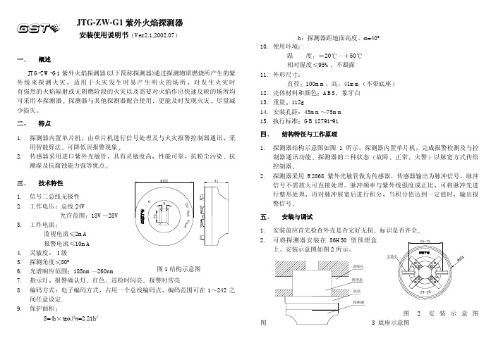
JTG-ZW-G1 紫外火焰探测器(以下简称探测器)通过探测物质燃烧所产生的紫 外线来探测火灾 适用于火灾发生时易产生明火的场所 对发生火灾时 有强烈的火焰辐射或无阴燃阶段的火灾以及需要对火焰作出快速反映的场所均 可采用本探测器 探测器与其他探测器配合使用 更能及时发现火灾 尽量减 少损失
二 特点
1. 探测器内置单片机 由单片机进行信号处理及与火灾报警控制器通讯 采 用智能算法 可降低误报警现象
2. 传感器采用进口紫外光敏管 具有灵敏度高 性能可靠 抗粉尘污染 抗 潮湿及抗腐蚀能力强等优点
三 技术特性
1. 信号二总线无极性
2. 工作电压 总线 24V
允许范围 18V 28V
3. 工作电流
检查紫外光敏管接线是否良好 紫外光敏管两端是否有 300V 左右高压 若 有再检查集成电路 4011 及周围电路是否正常 若无检查振荡电路 T1 VT3 等 3. 误报警
检查紫外光敏管是否老化 300V 电压是否过高 4011 及周围电路是否损坏 4. 报警时指示灯不亮
指示灯损坏或线路板连接线断路
八 注意事项 在下列情形的场所 不宜使用本探测器
7. 调试 系统连线接好后 接通电源 控制器注册应正常
火焰探测器安装使用说明书模板

火焰探测器安装使用说明书(安装、使用产品前,请先阅读本手册)A710系列火焰探测器设计手册上海翼捷工业安防技术有限公司上海安誉智能科技有限公司.10工作原理1•火焰特征1.1火焰辐射特征火焰燃烧过程释放出紫外线、可见光、红外线,其中红外部分可分为近红外、中红外、远红外三部分。
阳光、电灯、发热物体等均有热辐射,其辐射光谱随物体不同而不同,辐射光谱可能包括紫外线、红外线、可见光等0. 2 0.4 0.8 2.7 4.3波长微米1.2光谱如上图所示,自然界中按不同范围的波长分为紫外部分和红外部分,燃烧物体对应其不同波长的光谱,发出不同程度的辐射。
1.3火焰闪烁特征火焰的闪烁频率为0.5Hz -20Hz热物体、电灯等辐射出的紫外线、红外线没有闪烁特征2.探测器工作原理2.1 紫外火焰探测器2.1.1 基本原理经过检测火焰辐射出的紫外线来识别火灾2.1.2 紫外光谱0.18um-0.4um ( 180nm-400nm )太阳光中小于300nm 的紫外线基本被大气层全部吸收,到达地球表面的紫外线都大于300nm2.1.3 紫外探测的优缺点优点:反应速度快缺点:易受干扰2.1.4 紫外火焰探测原理选用180nm-260nm 的紫外传感器,对日光中的紫外线不敏感2.2 双波段红外火焰探测器2.2.1 基本原理经过检测火焰辐射出的红外线来识别火灾2.2.2 红外光谱红外线按照波长分为近红外、中红外、远红外空气中的气体(如CO、CO2 等)对特定波长的红外线具有强烈的吸收作用2.2.3 双波段红外火焰探测原理选用两个波长的热释电红外传感器,来检测火焰辐射的红外线一个波长的热释电红外传感器用于检测含碳物质燃烧释放CO2 引起的特定波长红外光谱的变化;一个波长的热释电传感器用于检测红外辐射的能量。
两个不同波长的传感器向结合,有效区分发热体而非火焰释放的红外线,避免误报警。
2.3 三波段红外火焰探测器2.3.1 基本原理经过检测火焰辐射出的红外线来识别火灾。
紫外线火焰检测器ZWJ说明书

ZWJ-306紫外线火焰监测器产品名称:ZWJ-306紫外线火焰检测器关键字搜索:ZWJ-306紫外线火焰检测器、紫外线火焰监测器、火焰检测器、火焰监测器一、概述:ZWJ-306紫外线火焰监测器主要用于燃气、燃油工业燃烧器的火焰监测,燃料燃烧时辐射一定频率的光谱,UV传感器对燃烧光谱不间断采集分析,经智能频率合成模块计算输出模拟火焰信号,火焰信号经电容自动跟随漂移反馈模块电路处理得出稳定火焰信号,从而实现UV传感器至监测器间的分布电容自动匹配,传感器与监测器间的连接距离最远可达600M米而无需调整电容匹配电位器,同时监测器还设置监测灵敏度调节电位器和熄火延时关阀调节电位器,进一步方便用户使用。
传感器信号线(4号线)抗对地、对火线短路,抗分布电容并自动调整,检测灵敏度高,抗干扰性强,不受日光、红外热辐射、炉堂高温等的影响,确保燃烧系统安全运行。
本产品获中国专利,专利号为14545。
二、主要技术参数:工作电源:200V~240V·AC 50/60Hz功耗:<3W传感器工作电流:<50μA传感器光谱范围:185~280nm检测距离:不小于2m(1支火焰高度为45mm蜡烛)检测响应时间:<0.2S熄火延时关阀时间:1~7秒可调点火时间:5~7秒传感器与监测器连接电缆:不小于600m三、监测器工作程序:通电后,监测器同时输出定时点火信号(端子5、6)及燃料阀打开信号(端子6、7),若点火成功,则点火信号关闭后继续输出燃料阀打开信号;若点火失败,则关闭点火信号及燃料阀打开信号,并输出无源报警信号。
四、监测器接线端子定义如下:1、电源火线2、电源零线2、3、4对应接UV传感器线码2、3、45、6输出点火信号,220V·AC容量5A6、7输出阀开信号,220V·AC,容量5A8、9输出无源常开,有火闭合9、10输出无源常闭,有火断开五、尺寸:壳体:ABS工程塑料(防水型)颜色:灰色体积:158×90×41mm安装尺寸:182×52mm矩形安装(长宽预留200×100)安装孔:φ7.0mm探头安装螺纹:M20×1.5探头直径:φ36mm探头长度:138mm六、安装:紫外线火焰监测器是一种非接触式火焰监测器,用户安装时请将探头对准火焰。
95-8546 指令 UVIR 火焰探测器系列 X5200、X5200G 和 X5200M说明书

Instructions UVIR Flame Detector Series X5200, X5200G, and X5200MTable of ContentsDESCRIPTION (1)Outputs (1)LED (2)o i (Optical Integrity) (2)Communication (3)Data Logging (3)Integral Wiring Compartment (3)SIGNAL PROCESSING OPTIONS (3)IR Detector Options (3)UV Detector Options (4)GENERAL APPLICA TION INFORMA TION (4)Response Characteristics (4)False Alarm Sources (5)Factors Inhibiting Detector Response (5)IMPORT ANT SAFETY NOTES (6)INST ALLATION (7)Detector Positioning (7)Detector Orientation (7)Protection Against Moisture Damage (8)Wiring Procedure (8)Setting Device Network Addresses(EQ and EQP Models Only) (14)ST ARTUP PROCEDURE (15)Fire Alarm Test..........................15TROUBLESHOOTING .. (15)MAINTENANCE (16)Cleaning Procedure (16)o i Plate Removal and Replacement . . . . . . . . .16 Periodic Checkout Procedure (17)Clock Battery (17)FEATURES (17)SPECIFICA TIONS (18)REPLACEMENT P ARTS (20)Replacement Parts List (20)DEVICE REP AIR AND RETURN (20)ORDERING INFORMA TION (20)Accessories (20)X5200 Series Model Matrix (21)APPENDIX A – FM APPROVAL AND PERFORMANCE REPORT (22)APPENDIX B – CSA APPROVAL (27)APPENDIX C – ATEX APPROVAL (28)APPENDIX D – IECEx APPROVAL (30)APPENDIX E – EN54 APPROVALS (31)APPENDIX F – ADDITIONAL APPROVALS (32)The detector signals a fault condition when less than half of the detection range remains. This is indicated by the Faultoutput and is evident by the yellow color of the LED on the face of the detector. See the "Troubleshooting" section for further information.Magnetic o i / Manual o iThe detector also incorporates both Magnetic o i (Mag o i ) and Manual o i (Man o i ) features that provide the same calibrated test as the Automatic o i , and in addition actuates the Alarm output to verify operation for preventive maintenance requirements. These features can be performed at any time and eliminate the need for testing with a non-calibrated external test lamp.CAUTIONThese tests require disabling of all extinguishing devices to avoid release resulting from a successful test.The Mag o i test is performed by placing a magnet at the location marked "MAG OI" on the outside of the detector (see Figure 2). The Man o i test is accomplished by connecting the o i lead (terminal 22) to power supply minus via an external switch. The magnet or switch must be held in place for a minimum of 6 seconds to complete the test. Either of these test methods activates the calibrated UV and IR emitters. If the resulting signal meets the test criteria, indicating that greater than half of the detection range remains, the fire alarm output of the detector is activated. On models with relay, 0–20 mA, or HART outputs, this condition remains until the magnet is removed or the switch is released, regardless of whether the detector has been configured for latching or non-latching operation. The fire alarm output condition stays active for three seconds on Eagle Quantum Premier models.If less than half of the detection range remains, no alarm is produced and a fault is generated. The fault indication can be reset by momentarily applying the Mag o i or Man o i switch. In this case, the detector's optics should be cleaned and the o i tests should be repeated. See the "Cleaning Procedure" section of this manual for details.NOTERefer to Appendix A for FM verification of the o i MUNICATIONThe detector is furnished with an RS-485 interface for communicating status and other information with external devices. The RS-485 supports Modbus protocol, with the detector configured as a slave device.For HART communication, connect a HART communicator across a 250 ohm resistor in the 0-20 mA loop. HART output models do not support RS-485 Modbus protocol.NOTEThe EQP model uses LON/SLC communication. RS-485 and HART communication are not available on the EQP model.DATA LOGGINGData logging capability is also provided. Status conditions such as normal, power down, general and o i faults, pre-alarm, fire alarm, time and temperature are recorded. Each event is time and date stamped, along with the temperature and input voltage. Event data is stored in non-volatile memory when the event becomes active and again when the status changes. Data is accessible using the Inspector Connector accessory, RS-485, or the EQP Controller.INTEGRAL WIRING COMPARTMENTAll external wiring to the device is connected within the integral junction box. The detector is furnished with four conduit entries, with either 3/4 inch NPT or M25 threads.SIGNAL PROCESSING OPTIONSThe X5200, X5200G, and X5200M feature signal processing options for both the UV and IR sensor. These options determine the type of logic that the detector will use for processing fire signals to customize the detector to the application. IR DETECTOR OPTIONSThe IR detector in the X5200, X5200G, and X5200M can be programmed for: –TDSA enabled–Both TD SA and Quick Fire enabled (either initiates fire alarm)Time Domain Signal Analysis (TDSA)The TD SA signal processing technique analyzes the input signal in real time, requiring the IR signal to flicker randomly in order to recognize it as a fire ing TD SA signal processing, the detector ignores regularly chopped blackbody sources (occurring in areas where moving conveyors and hot objects in proximity to one another result in a regularly chopped IR signal), because it looks for a less uniform signal. However, in the presence of a regularly chopped signal, the detector is more susceptible to false alarms due to sporadic IR that functions as a trigger when occurring in conjunction with the regularly chopped signal.Quick Fire (High Speed)The Quick Fire (High Speed) feature can be used in conjunction with the TD SA signal processing method. This method overrides TDSA requirements in the event of a sudden and intense signal, such as the result of a flash fire. When Quick Fire is activated, the detector is capable of responding to an intense fire signal in less than 30 milliseconds (0.030 seconds). Using the Quick Fire feature in conjunction with TDSA signal processing allows the detector to provide a high speed response to a large, non-flickering fire (such as in high pressure gas applications). Additionally, when the Quick Fire feature and TDSA signal processing are used in conjunction, the detector maintains an ability to respond to fires that start very small and grow in size and intensity over time.UV DETECTOR OPTIONSThe UV detector output (measured in counts per second) is compared to the fire threshold (the “sensitivity” setting). If the radiant energy level from the fire exceeds the selected alarm threshold level, the fire alarm output is activated. In every application, it is crucial to ensure that the radiant ultraviolet energy level from the expected fire at the required distance from the detector will exceed the selected sensitivity level.The UV detector in the X5200, X5200G, and X5200M can be programmed for:–Arc Rejection–Standard Signal ProcessingArc RejectionThe Arc Rejection mode enables the detector to prevent nuisance fire alarms caused by UV from short-duration electrical arcs or electrostatic discharge, while maintaining the ability to reliably detect the UV radiation given off by a flame. Typical applications that benefit from arc rejection logic include electrostatic coating processes and uncontrolled environments where transient UV sources can be present, such as many typical outdoor applications. Most false alarm sources have short transient UV signatures, while fire creates a long UV signature over many seconds. Most fires are detected in a few seconds (see response times in Appendix A).Standard Signal ProcessingStandard signal processing is recommended for high-speed suppression systems only. To allow for high-speed operation, the standard processing mode does not incorporate the arc rejection programming. This mode should only be used in a controlled, indoor environment.GENERAL APPLICATION INFORMATIONRESPONSE CHARACTERISTICSResponse is dependent on the detector's sensitivity setting, arc rejection, and time delay settings. Other factors include distance, type of fuel, temperature of the fuel, and time required for the fire to come to equilibrium. As with all fire tests, results must be interpreted according to an individual application.See Appendix A for third-party approved fire test results. Additional fire test results are available from Det-Tronics.WeldingElectric arc welding is a source of intense ultraviolet radiation. UV radiation from arc welding readily scatters and can deflect across significant distances, even when direct obstructions exist. Any open door or window can allow nuisance UV radiation from arc welding to enter an enclosed area, causing a possible response from the UV detector.It is recommended that the system be bypassed during welding operations in situations where the possibility of a false alarm cannot be tolerated. Gas welding mandates system bypass, since the gas torch is an actual fire. Arc welding rods can contain organic binder materials in the flux that burn during the welding operation and are detectable by the detector. Welding rods with clay binders do not burn and will not be detected by the detector. However, system bypass is always recommended, since the material being welded may be contaminated with organic substances (paint, oil, etc.) that will burn and possibly cause the detector to alarm.Artificial LightingThe detector should not be located within 3 feet (0.9 m) of artificial lights. Excess heating of the detector could occur due to heat radiating from the lights.EMI/RFI InterferenceThe detector is resistant to interference by EMI and RFI, and is EMC Directive compliant and CE marked. It will not respond to a 5 watt walkie-talkie at distances greater than 1 foot (0.3 m).Non-Carbon FiresThe UV/IR Fire Alarm response of the detector is limited to carbonaceous fuels. It should not be used to detect fires from fuels that do not contain carbon, such as hydrogen, sulfur, and burning metals. The Auxiliary relay can be configured to change states upon a UV alarm only. When configured in this manner, the UV sensor within the detector can be used to detect non-carbonaceous fires.FALSE ALARM SOURCESUV:The UV sensor is solar blind to the ultraviolet component of solar radiation. However, it may respond to sources of UV besides fire, such as arc flash, electric arc welding, grinding metal, lightning, high voltage corona, x-rays, and gamma radiation.NOTERadiation generated by false alarm sources suchas periodic lightning or sparks in the area may beeffectively ignored by the detector using the arcrejection feature or time delay.IR:The detector has been designed to ignore steady state infrared sources that do not have a flicker frequency characteristic of a fire, however, it should be noted that if these steady state infrared sources are hot enough to emit adequate amounts of infrared radiation in the response range of the IR sensor and if this radiation becomes interrupted from the view of the detector in a pattern characteristic of a flickering flame, the IR sensor can respond.Any object having a temperature greater than 0° Kelvin (–273°C) emits infrared radiation. The hotter the object, the greater the intensity of the emitted radiation. The closer the infrared source is to the detector, the greater the potential for a false alarm. The IR sensor can respond to IR radiation sources that can meet the amplitude and flicker requirements of the detector such as vibrating hot objects.Although the detector is designed to reduce false actuations, certain combinations of ambient radiation must be avoided. For example, if IR radiation with an intensity that exceeds the fire threshold of the IR sensor should reach the detector as a flickering signal, and if at the same time an electric arc welding signal also reaches the detector, an alarm output will be generated. FACTORS INHIBITING DETECTOR RESPONSE WindowsGlass and Plexiglas windows significantly attenuate radiation and must not be located between the detector and a potential flame source. If the window cannot be eliminated or the detector location changed, contact Det-Tronics for recommendations regarding window materials that will not attenuate radiation.ObstructionsRadiation must be able to reach the detector in order for it to respond. Care must be taken to keep physical obstructions out of the line of view of the detector. In addition, UV or IR absorbing gases or vapors must not be allowed to accumulate between the detector and the protected hazard. See Table 3 for a list of these substances.SmokeSmoke will absorb radiation. If accumulations of dense smoke can be expected to precede the presence of a flame, then detectors that are used in enclosed areas should be mounted on the wall approximately 3 feet (0.9 m) from the ceiling where the accumulation of smoke is reduced.Detector Viewing WindowsIt is important to keep the detector viewing windows as free of contaminants as possible in order to maintain maximum sensitivity. Commonly encountered substances that can significantly attenuate UV and/or IR radiation include, but are certainly not limited to, the following:–Silicones–Oils and greases–Dust and dirt buildup–Paint overspray–Water and iceWDo not open the detector assembly in a hazardousCAUTIONThe wiring procedures in this manual are intendedCAUTIONTo prevent unwanted actuation or alarm,CAUTIONThe UVIR flame detectors are to be installed inIR VIEWING WINDOWUV VIEWING WINDOWDETECTOR STATUS INDICATOR Figure 1—Detector Orientation Relative to HorizonWAll entries must contain appropriately rated plugsCAUTIONInstallation of the detector and wiring should beFigure 4—Detector Terminal BlockWThe network address switches are located within ADDRESS SWITCHES SENSOR MODULEREMOVED FROM HOUSINGA2191Wo avoid a potential electrostatic discharge (ESD),WThe sensor module (“front”CAUTIONDisable any extinguishing equipment that is 2. Clean the viewing windows and reflective surfacesof the o i plate using a clean cloth, cotton swab,CAUTIONreplace the o iLOOSEN TWO CAPTIVE SCREWSGRASP VISOR ANDREMOVEC2135Figure 18—o i Plate Removal95-8546X3301 Multispectrum IR Flame DetectorFlexSonic ® AcousticLeak DetectorPointWatch Eclipse ® IR Combustible Gas Detector FlexVu ® Universal Displaywith GT3000 Toxic Gas Detector Eagle Quantum Premier ®Safety SystemC orporate Office6901 West 110th StreetMinneapolis, MN 55438 USA All trademarks are the property of their respective owners. © 2017 Detector Electronics Corporation. All rights reserved.Det-Tronics manufacturing system is certified to ISO 9001— the world’s most recognized quality management standard.Phone: 952.946.6491 Toll-free: 800.765.3473Fax: 952.829.8750***************************。
EVC-IR火焰探测器技术手册说明书

Nittan Europe LtdHipley StreetOld WokingSurreyGU22 9LQDocument:Product:Reference:Description:Technical ManualEVC-IRF04-60044.Conventional Infrared Flame Detector (EVC-IR) is a flame detectorwhich monitors infrared energy emitted during a fire.PAGE 1 OF 61.0General.The Conventional Infrared Flame Detector (EVC-IR) is a flame detector monitoringinfrared energy emitted during a fire. The Flame detectors are designed to monitor flame in large and high-ceiling areas such as an atrium, or a gymnasium where Heat or Smoke detectors are unable to detect fires quickly.In addition, if this detector is installed near machinery which could be an ignition source, this detector can detect small fires at an early stage.Main Characteristics:•Provides reliability and cost-effectiveness by employing dual infrared wavelengths.±50°.•Provides a supervision angle of 100°()•Omniview 360°LED Fire Alarm Indicator permits visibility from any angle.•Embedded Self-test function detects a sensor fault and contamination of Element Window Glass.2.0Part Identification.Figure 1: Detector appearance3.0Specification.Product Model EVC-IRType Conventional Infrared Flame DetectorApprovals 0832-CPD-1081 Standard: EN54-10:2002/A1:2005 Detection Method CO2 Resonance Emission, Flame Flicker, Dual WavelengthsOperating V oltage DC24V(Operating Voltage 10 ~30V)Stabilisation Time < 1 minReset Remove power (or reduce Voltage across terminals 3 and 1.6 to blowholding voltage), for > 1 sec.Power on Reset TimeNote 1:4secQuiescent Current Consumption 130µA()at DC24VAlarm Current 50mA@24V, (Internal 375Ω resistor in series with 6Vdrop) RIL: 2mASupervision Distance 30m (17m~30m)17m 19m 20m 25m 30mViewing Angle 100º Max (±50º)100º 90º 80º 60º 20º LED Indicator Alarm :LED(RED)ON Fault :RIL PulsesAmbient Condition -10 ~55℃Materials Head:PC/ABS BlendWeight Head:127gNote 1: Period from when the detector starts operation, during which the detector will not reset3.1Detection Method.The detector monitors fire parameters in the following three ways.CO2 Resonance EmissionBy analysing the light spectrum emitted from a fire, it is determined that the light reaches a peak at 4.3μm in the Infrared area as shown in Figure 2. This is called CO2 Resonance Emission emitted from high temperature CO2, which is a combustion product. The detector detects fire by monitoring this light emission.Figure 2: Diagram for Spectrum of Flame and Temperature ObjectsFlame Flicker FrequencyA fire exhibits expansion and contraction influenced by the balance of burningmaterials, oxygen and heat energy. This causes flame flicker. Pyroelectric infrared detection which is used for this detector considers this flicker as a change of the amount of infrared. It does not have sensitivity to a heat and light source since the amount of light for these sources does not change.The frequency of fire flicker is considered to be 1~10Hz, and the frequency filter circuit removes excess noise.Dual Wavelength SystemAll objects which have temperature emit infrared. However, the black body infrared does not have a characteristic peak. To utilise this difference, a second wavelength sensor has been added and the size is compared. i.e. it detects fire when the output of the first wavelength is greater than the one of the second wavelength.i.e. If the first wavelength level > the second wavelength level ,detects fire Conversely, if the first wavelength level < the second wavelength level ,does not signal a fire conditionBy doing this, it is possible to discriminate the heat source which would be a cause of false alarm more effectively.3.2 Indicator (Omniview)Employing a 360°Omniview indicator, the detector can be installed in any orientation. Sensors can be installed vertically or horizontally. Indicator can be viewed from any angle.Re l a t i v e I n t e n s i t y [%]3.3Self-test FunctionThis detector has a self-test function which checks for contamination of theElement Window Glass and the status of the sensor. This allows the detector tomaintain required sensitivity.If an internal fault is detected, the external RIL terminal pulses.Contaminated Window: 1 pulse every 4sSensor fault: 2 pulses every 4s3.4Connection ConfigurationNEU Connections:Terminal 1: -ve Power In from PanelTerminal 3: +ve Power (12-32V)Terminal 5: RILTerminal 6: -ve Power to Next device4.0Installation Recommendations1) Places where special protection is required or desired for preservation purposes National and Historical Buildings, Libraries, Museums, Temples, Churches, and Private Housings2) Hazardous material Collection and storage areas Car Parks, Garages, Package Distribution Centre, Electric Power Generating Rooms, Truck Yards, Engine Test Rooms3) Flammable Materials Fabrication Areas Paper Mills, Wood Working Factories, Paint Shops, Rubber Product Manufacturers, Machine Shops, Garage Recycling Centres4) Warehouses Paper, Wood, Resins, Rubber, Paper Boards, Clothing 4) Rubbish Collection Areas Garages, Used Tires, Scrap Yards, Paper recyclingCentres5) Others Prevention of fire spread, Forest Fires, Machinery EngineRoomsInstallation Notes:•Supervision distance changes with viewing angle•To change the supervision direction of the detector, a separate sensitivity adjustment is needed.•Please do not install the detector where sufficient maintenance cannot be provided. •Please do not place any obstacles between the detector and the monitored object.Even transparent windows, such as glass or plastics, can be obstacles, to Infra-red radiation.•Sensitivity reduction and detection fault may occur where vibration and electromagnetic interference occur constantly.•Sensitivity reduction and detection fault may occur where there is a constant high heat source flicker.Unsuitable Installation Areas•Where Corrosive gases would be produced•Where flame is a normal condition i.e.: kitchens•Where high temperature is the norm•Direct sunlight•Where a large amount of smoke may occur as the norm•Where a large amount of water vapour is normal•Where condensation is common5.0Maintenance/Inspection.A Maintenance plan corresponding to the installation environment shall be considered.Please ensure routine maintenance/inspection, including cleaning is conducted.。
A710UV紫外技术参数表

4~20mA 电流输出(选型) 丢失故障:0± 1mA 检查故障:2mA ±10% 正常:5mA ±10% 警告:10mA ±5% 报警:15-20 mA ±5% 环路电阻(Resistance loop):100-600 Ohm RS-485 输出(选配) Hart接口(选配) 温度要求 工作湿度 电磁兼容及环 境试验 防爆认证 防护等级 壳体材料 电气接口 满足标准 重量 储存温度:-40℃~85℃ ≤95%RH(40+2℃)(不结露) 符合国家GB16838标准要求,应用于高温、高盐、高温和低温等环境。抗点瞬变、 浪涌电压干扰、抗静电干扰 ExdⅡCT6/DIP A20 TA,T6 / ExdⅡBT6 IP 66 铝合金,表面烤漆 2*M20*1.5MMISO (可根据需要配置变径转接头) GB15631-2008 1.7kg GB12791-2005 GB3836-2000系列标准 RS-485标准接口,支持MODBUS协议,可用于PLC等设备 支持HART协议,1200波特调制解调接口 工作温度:-10℃~50℃ 标准型:-40℃~70℃
3、A710 系列探测器外形尺寸图
4、A710 系列安装支架外形图
5、安装方式示意图
6器连接示意图
8、A710 系列火焰探测器与工业自动化系统 DCS/PLC 的连接
1、A710/UV 紫红外复合型火焰探测器
2、技术规格表
工作电压 工作电流 光谱范围 视角范围 探测距离 DC24V, 电压范围: DC18~30V 25mA (监视) 35mA(报警) UV185-260nm 120° 燃烧物 正庚烷 汽油 柴油 酒精 LPG丙烷 火源大小 0.3m×0.3m 0.3m×0.3m 0.3m×0.3m 0.3m×0.3m 气体火焰,1616羽 探测距离 25米 25米 20米 20米 20米 50mA(自检)
和讯智能 FS20X 和 FS24X 火焰探测器说明书

Fire DetectionFS20X and FS24XFlame DetectorsFS20X DetectorAdvanced Multi Spectrum (UV/Dual IR/VIS) Flame Detector.Based on the foundation of the highly successful and reliable SS4 detector, the FS20X detector represents a quantum leap in integrating Infrared and Ultraviolet sensing technologies. The FS20X detector is a Multi-Spectrum and UV/Dual IR/VIS and flame detector with a proven UV solar-blind sensor. FS20X delivers a faster response and fewer false alarms, performs in a wider ambient temperature range, with a much longer detection range compared to conventional UV/IR detectors.Conventional and older technology UV/IR detectors, using narrow band4.3 micron IR sensors, will not always respond to smoky fires or if thedetector lens is contaminated with oil and other substances since bothUV and 4.3 micron signals are attenuated, obscured or absorbed by thicksmoke or detector lens contaminations. All UV sensors will be attenuatedto some degree.DIMENSIONSSide and Back Views (All Dimensions in mm)Superior Technology Dual microprocessors enable fast and reliable performance. The master microprocessor performs high-speed digital sampling and signal processing calculations while the slave microprocessor handles sensor data, performs communications, self-diagnostics and manages interfaces and memory for storing event log and FirePic™ data. The FS20X detector hasa detection range in excess of 60 m (200 feet) (very high sensitivity setting) for the detection of a0.1m2 (one square-foot) Heptane reference fire and has a field of view with a greater volumetric coverage than most UV/IR detectors. This means fewer detectors can be used to cover an area as compared to other manufacturers’ detectors.The FS20X detector using advanced algorithms for signal processing and fire and flame analysis to alarm to most fires in all industrial environmental conditions. If the detector’s UV signal is degraded due to heavy smoke or a contaminated lens, FS20X’s patented WideBand IR™, Near Band IR andVisible sensors will still alarm to fire, albeit at a reduced sensitivity and slower response time.General SpecificationFEATURES• P atented WideBand IR™ Infrared combined with Ultraviolet• Detection range greater than 60 m (200 feet) to 0.1 m2 (1 sq. ft.) heptane fire• Patented Electronic Frequency Analysis• Visible sensor for optimum false alarm rejection• Selectable detection sensitivities• Solar blind 90° field of view• Dual microprocessors for reliable performance• Real-time clock for accurate time dating of events• FirePic™ — Up to 6 pre-fire event data storage• Event log — Up to 200 events with date and time stamp• Built-in RS-485 ModBus communication• Built-in non-isolated 4-20 mA analog output (sink or source)• Alarm, Fault and Fire Verification relays• Automatic Optical Path and Electronic self-test• Patented Electronics Module for component protection with plug-in terminations for easy field installation• Two M25 conduit entries• Low power consumption • High RFI and EMI immunity• FM hazardous area approved• Ex d ATEX /IECEx approved• CU-TR approved• INMETRO approved• Meets SIL 2 requirements• Certified to EN54-10:2002• FM 3260 performanceBENEFITS• Detects hydrocarbon and non-hydrocarbon fuel fires in all environmental conditions• Wide operating temperature range• Arc welding immunity• False alarm rejection• Minimal maintenance for trouble-free operation• PC software and interface module (FSIM) for fault diagnostics real-time graphs (RTGs), and downloading of FirePics™ and event log•Suitable for a wide variety of applicationsFS24X DetectorTrue triple IR wide band sensing and sophisticated detection algorithms.FS24X provides wideband M ulti-Spectrum Triple IR (IR/IR/IR/Visible) flame detection. It is part of our FSX family of advanced technology Electro-Optical fire detectors. Using our patented* WideBand IR™, WideBand 4.3 micron IR™, and Visible detection technology, the FS24X sets the standard for flame detection. Sophisticated software algorithms and dual microprocessors ensure that the FS24X has the highest fire detection performance combined with optimal false alarm rejection.The WideBand IR™ Infrared technology using high-speed solid-state Quantum sensors allows detection of all types of fires, hydrocarbon and non-hydrocarbon, in all weather conditions.The FSX family of detectors feature our patented* FirePic data storage and information retrieval facility. FirePic™ records pre-fire data, which can be recovered from the detector’s non-volatile flash memory for post fire analysis and determination of the fire cause. Additionally, unique Real-Time Graphing (RTG™) allows viewing of the data which the detector senses in each waveband. A combination of outputs makes the FSX detectors useful beyond the immediate alarm and help in both protection and investigation of fire events in today’s demanding industrial requirements.The FS24X detector has a detection range greater than 60 m (200 feet) (Very High Sensitivity setting) for the detection of a 0.1 m 2 (one square-foot) Heptane reference fire and has a cone of vision far greater in volumetric coverage than any other Multi-Spectrum IR detector. This means fewer detectors can be used as compared to other manufacturers’ detectors.Dual microprocessors provide a high level of fail-safe operation combined with fast and reliable performance. The master microprocessor performs high-speed digital sampling and signal-processing calculations, while the slave microprocessor handles various sensor data, performs communications, self-diagnostics and provides interface versatility and additional memory for storing Event Log and FirePic™ data.DIMENSIONSSide and Back Views(All Dimensions in mm)FEATURES• Patented WideBand IR™ technology• Patented Electronic Frequency Analysis™• V isible sensor for optimum false alarm rejection• Selectable detection sensitivities• Field-of-View: 90° cone-of-vision• Dual microprocessors for reliable performance• Real-time clock for accurate time dating of events• FirePic™ — pre-fire event data storage• Event log with date and time stamp• RS-485 ModBus communication• Non-Isolated 4-20 mA Analog output (sink or source)• Alarm, Fault and Fire Verification relays• A utomatic optical path and electronic self-test• P atented Electronics Module for components protection with easy plug-in terminations and field installation• T wo M25 conduit entries• Low power consumption• High RFI and EMI immunity • FM, ATEX, CE mark approvals• CU-TR approved• INMETRO approved• Meets SIL 2 requirements• Certified to EN54-10:2002• FM 3260 PerformanceBENEFITS• Detects hydrocarbon and non-hydrocarbon fuel fires in all environmental conditions• User selectable output options• Wide operating temperature range• Optimal false alarm rejection• Minimal maintenance for trouble-free operation• PC software and Interface Module (FSIM) for fault diagnostics, real-time graphics (RTGs), and downloading of FirePics™ and event log• Suitable for a wide variety of applications• Easy electronics module replacement• Test lamps for manual testingGeneral SpecificationFS20X certified 1175a/01 (LPCB); CPR 0832-CPR-F0515UKTel: +44 (0) 116 246 2000Fax: +44 (0) 116 246 2300******************************* FranceTel: +33 810 10 66 10Fax: +33 474 94 79 82************************ItalyTel: +39 02 518971Fax: +39 02 5189730*************************** Eastern EuropeT: +43 (0)1 600 60 30F: +43 (0)1 600 60 30-900 *************************Doc. Ref.: HON-BR-011-03_EN 01/17© 2016 Honeywell International Inc.。
- 1、下载文档前请自行甄别文档内容的完整性,平台不提供额外的编辑、内容补充、找答案等附加服务。
- 2、"仅部分预览"的文档,不可在线预览部分如存在完整性等问题,可反馈申请退款(可完整预览的文档不适用该条件!)。
- 3、如文档侵犯您的权益,请联系客服反馈,我们会尽快为您处理(人工客服工作时间:9:00-18:30)。
Aegis 上海安誉设计文件A705/UV 点型紫外火焰探测器技术规格书
1概述
本规格书描述了A705/UV 点型红外火焰探测器的主要技术规格,包括(但不限于)产品功能、技术参数、软件、硬件和光学系统的组成、安装调试、使用和维护方法等。
本规格书根据 A705/UV 设计文件编制,随着技术进步和产品应用实践,安誉将在国家标准和 3C 管理相关规则限定的范围内对产品进行持续改进,使产品能够持续的满足用户的需求。
一旦实施产品改进,安誉有权修订和更新本规格书。
请关注本规格书最新版本。
2产品功能和组成
A705/UV 可应用于需要对火焰实施监控的场所,快速发现可能引起火灾的燃烧火焰,及时发出火灾警报。
A705/UV 使用冷阴极紫外光电管将火焰燃烧参数转换为电脉冲信号,之后将信号输入工业计算芯片进行运算和处理,配合 UVdetecter@anysafe 专用智能控制软件,可以及时发出火灾警报。
A705/UV 采用铝压铸隔爆壳体,具有良好的防爆和防护特性,耐腐蚀、抗老化,可以长期工作于室内、室外以及各种特殊的工业场所。
设计文件3技术参数
●故障继电器,故障时动作,输出触点 1A@30VDC 1A@250VAC
●串行通讯接口
3.3探测性能和保护范围
说明:
1、上图的中轴线代表与探测窗口垂直;
2 、上图显示 100% 位置为最大探测距离
D(max),各个角度的探测距离可由图上黑
3、色边缘部分的百分比乘以 D(max)计算
得出;
4、各类环境下的最大探测距离 D(max)详
见左表:
3.4环境参数
项目规格
工作温度-10℃ —+55℃
工作湿度≤95%HR,无结露
储存温度-20℃ —+60℃
●用户设置(缺省默认出厂设置):报警阈值、报警延迟时间。
●工厂功能:维护、标定、补偿参数信息、合格标识、软件版本、产品
ID 等。
需专业人士操作和密码授权
4主要电路及软件
电路部分主要包括传感器、DC/DC 变换器、隔离器放大器、工业处理单元、外围驱动电路、电源和 EMC 电路等。
电原理框图见下图:
A705/UV 电原理框图
MCU 内置 UVdetecter@anysafe 专用软件,使用安誉紫外火焰探测算法和判据规
则。
5 外壳
为满足探测器长期稳定工作和防爆要求,A705/UV 使用一个铝压铸结构的外壳。
外壳分为
壳体和底盖。
为保证防爆性能壳体和底盖之间采用螺纹连接,并在连接面加装一个橡胶密封
圈。
进线孔和安装挂钩均设置在壳体上,以方便接线操作。
使用一个塑料内壳固定和保护电路部分,内壳前面板仅露出紫外火焰传感器和指示灯,后
部仅露出接线端子,以防止安装和接线时对电路造成损坏。
A705/UV 外形结构和尺寸见下图:
设计文件
外形结构和尺寸
6光学部分
在 A705/UV 面板上设置一个椭圆光学窗口,使用高纯度石英玻璃作为窗口玻璃。
利用高纯度石英玻璃优良的紫外波段透射能力,满足火焰探测的需要,同时利用其较高的强度和硬度,满足防爆隔爆的要求。
7安装
A705/UV 的布设位置和高度通常由有资质的设计部门规定,遵循国家标准 GB50116-2008 火灾自动报警系统设计规范、GB50166-2007 火灾自动报警系统施工就验收规范、GB50314-2006智能建筑设计标准的要求。
A705/UV 采用一个坚固的铝压铸吊架安装和固定探测器,吊架的外形和固定尺寸见下图:
安装吊架和安装孔距示意图
根据使用要求和环境条件,探测器可以采用壁挂式安装和吊顶式安装。
安装基准面应为结实的木质、金属或水泥结构。
悬挂方法见下图:。