GE300控制器说明书
GE300控制器说明书-推荐下载

目录一、概述‥‥‥‥‥‥‥‥‥‥‥‥‥‥‥‥‥‥‥‥‥‥‥‥‥‥‥‥‥‥11.1说明‥‥‥‥‥‥‥‥‥‥‥‥‥‥‥‥‥‥‥‥‥‥‥‥‥‥‥‥‥21.2控制器特点‥‥‥‥‥‥‥‥‥‥‥‥‥‥‥‥‥‥‥‥‥‥‥‥‥‥31.3技术指标‥‥‥‥‥‥‥‥‥‥‥‥‥‥‥‥‥‥‥‥‥‥‥‥‥‥‥4二、型号、安装和接线2.1选型‥‥‥‥‥‥‥‥‥‥‥‥‥‥‥‥‥‥‥‥‥‥‥‥‥‥‥‥‥6 2.2安装尺寸及说明‥‥‥‥‥‥‥‥‥‥‥‥‥‥‥‥‥‥‥‥‥‥‥‥7 2.3接线端子说明‥‥‥‥‥‥‥‥‥‥‥‥‥‥‥‥‥‥‥‥‥‥‥‥‥8 2.4接线图‥‥‥‥‥‥‥‥‥‥‥‥‥‥‥‥‥‥‥‥‥‥‥‥‥‥‥‥92.5与常用变频器接线表‥‥‥‥‥‥‥‥‥‥‥‥‥‥‥‥‥‥‥‥‥‥9三、操作与功能参数‥‥‥‥‥‥‥‥‥‥‥‥‥‥‥‥‥‥‥‥‥‥‥‥‥103.1面板显示操作说明‥‥‥‥‥‥‥‥‥‥‥‥‥‥‥‥‥‥‥‥‥‥113.2功能参数表及说明‥‥‥‥‥‥‥‥‥‥‥‥‥‥‥‥‥‥‥‥‥‥12四、显示项目及故障说明‥‥‥‥‥‥‥‥‥‥‥‥‥‥‥‥‥‥‥‥‥‥‥13五、附录5.1标准两泵循环软起动加泄压阀方式接线图5.2标准三泵循环软起动方式接线图5.3标准四泵循环软起动方式接线图一、概述1.1说明本手册包含GE300系列微机控制器的安装、操作和配置信息。
在使用GE300系列微机给水控制器之前,请您仔细阅读本使用说明书,并请妥善保存。
由于我们始终致力于产品的不断升级和完善,因此,本公司提供的资料如有变动,恕不另行通知。
1.2控制器特点本产品是应广大用户的要求最新推出的高性能微机给水控制器。
采用高品质元件、材料及融合最新的控制技术而成;和变频器组合在一起,即可构成民用、工业、消防等行业适用的微机变频调速恒压供水系统。
●采用模糊控制原理,自动优化时无需调整控制器参数,响应快、精度高、泵切换时管网冲击小。
●具备自动定时换泵,定时开关机设置,提高水泵平均使用寿命。
GE300控制器说明书
标准接线图
2.2
FWD CM1
与常用变频器接线表
FUJI 变频器端子 FRD CM 三肯变频器端子 FR DCM12 西门子变频器端子 5 9
微机控制器端子
CM2 D/A
GND VS
ACM VRF
4 3
一、 操作与功能参数 3.1 操作各按键名称和功能
3.1
面板操作说明
功能参数
功能码
代码 名称 参数值
说明书
一、概述 1.1 说明
本手册包含 GE300系列微机控制器的安装、操作和配置信息。
在使用 GE300系列微机给水控制器之前,请您仔细阅读本使用说明书,并请妥 善保存。 由于我们始终致力于产品的不断升级和完善,因此,本公司提供的资料如有变 动,恕不另行通知。
1.2 控制器特点 本产品是应广大用户的要求最新推出的高性能微机给水控制器。采用高品 质元件、材料及融合最新的控制技术而成;和变频器组合在一起,即可构成民用、 工业、消防等行业适用的微机变频调速恒压供水系统。 l l l l l l l l l l l l l 采用模糊控制原理,自动优化时无需调整控制器参数,响应快、精度高、泵切 换时管网冲击小。 具备自动定时换泵,定时开关机设置,提高水泵平均使用寿命。 系统提供休眠功能节能工作方式。 在压力不足需要加泵时,变频泵将自动降速,减少切换冲击。 增加锅炉补水,泄压阀压力区间控制选择。 变频器故障时,可选择自动转入工频运行。 一用一备、一用一补、两泵、三泵、四泵循环软起等功能,能满足不同用户的 需求。 简化键盘菜单式设定和调整工作状态。 参数在线编程,大大方便使用。 采用开关电源供电设计,具有宽电压适用范围,抗干扰能力强。 器件采用先进的 SMT(表面贴装)工艺,可靠性高。 保护及报警功能齐全,具有变频器故障,远传压力表断线、短路 故障、欠压超时、低水位报警指示。 完善的密码功能。
MegaPuls 300_400_500 使用说明书3

Operator controls and their functionsSP45:Welding ProcessThe Job only works using this welding process. The value can onlybe read and not altered. (This is part of the Job programming)1 =C onventional2 =P ulsed MIG3 =D ouble pulseRemark: Can only be selected if SP40 is set to 2.[1 - 3]SP46:Display TimeSetting of the time for which the display shows the value of thewelding current and the Arc Voltage.[5 - 120s]SP47:Wire Frozen signal *)(De-)activates the Wire frozen signal[On / OFF]t gv = Gas Pre-flow timet SP = Welding processt Fb = Burn-back timet gn = Gas post flow timet R = Pause time of approx. 0,4 st DFbr = Wire burn back time of approx. 0,2 st DFE = Wire frozen recognition time of approx. 5 s, durig this time the possibility of thewire frozen can be displayedWhen the wire frozen recognition signal is switched on: thenfollowing the final pulse, the wire frozen recognition signal isactivated on after the pause time t R. A voltage pulse of about U0 =75V and I max = 5A (the burn-back pulse time t DFbr). If the voltagemeasured is less than 50V, then the wire end has been frozen to the workpiece (frozen in the pool). In this case the Optional PCBAUT 01 activates a digital signal (high) for the duration of the timeset by t DFE.*) (only available with the Mechanised welding Optional PCB)Operator controls and their functionsSP48:Emergency Stop switch mode *) 0 = N ormally closed 1 = N ormally open [0 - 1] SP49:Collision warning switch mode *) 0 = N ormally closed 1 = N ormally open [0 - 1] SP50:No-Gas switch mode *) 0 = N ormally closed 1 = N ormally open [0 - 1] SP51:No-Gas switch mode *) 0 = N ormally closed 1 = N ormally open [0 - 1] SP52:Vd-Scaling *)Scaling for the voltage output of the Optional PCB AUT 01 to the selected Wire feed value (with respect to 10V), For example: A wire feed speed of V d =15 m/min should have U out =10V Setting SP52 = 15 [15, 20, 25, 30 m/min/10V] *) (only available with the Mechanised welding Optional PCB)Functions of the welding equipment5 Functions of the welding equipment5.1 Water circulation cooling with monitoringThe REHM-M EGA P ULS gas-shielded welding equipment is provided as standard with a water circulation cooling for the welding torch.The effectiveness of the cooling is continually checked by a flow monitor.With an insufficient water flow, and hence too low pressure, the monitor switches off the welding current. This is indicated by the error message "ERR H20". If the problem is resolved (e.g.: by topping up the water or removal of a leak or a fold in the water hose), The error message can only be extinguished by switching the machine off and then on again.5.2 Filtering of the cooling circuitThe clogged coolant is cleaned using a fine filter during refilling. As a result the welding torch is additionally protected from contamination and hence its dependability and service life improved.5.3 Standby mode of the systemThe standby mode achieves an energy saving and noise reduction, and also prolongs the service life of the water pump and of the fans.5.3.1 FansSpecial parameter SP 27: Setting OnThe fans are permanently switched on (continuous running).Special parameter SP 27: Setting AUT (Automatic)The fans are switched on or off depending on requirements.At the start of welding the fans are always switched on.They are switched off after a certain time after the end of welding, so that adequate cooling of the installed parts is always ensured.5.3.2 Water pumpSpecial parameter SP 28: Setting OnThe water cooling for the welding torch is permanently switched on (continuous running). Special parameter SP 28: Setting AUT (Automatic)Water cooling for the welding torch is switched on or off depending on requirements.At the start of welding water cooling is always switched on.It is switched off a short time after the end of welding, so that adequate welding torch cooling is always ensured.Functions of the welding equipment 5.4 Synergy controlThe matching ignition, starting, welding, crater filling and end program is always provided automatically and in the correct sequence by the data programmed and filed in the read-only memory (flash) for each working point.Thanks to the synergy control, the user does not need to make any settings whatsoever here.5.5 Compensation of mains fluctuationsMains voltage changes of +/- 10 % do not affect the pre-set welding power, i.e. they do not cause any change.5.6 Integrated digital balancing and calibration systemThe equipment is largely digital. As a result there are no potentiometers or other adjustable components.Manual adjustment and setting work is hence no longer necessary.5.7 Temperature monitoring of the power componentsWhen the max. temperature is exceeded, the welding current and the wire feed are automatically switched off; this is indicated by the display "ERR 10" in the digital display. After cooling down of the power components, the equipment switches back into operating condition by itself.The following conditions can cause a response by the temperature switch:- exceeding of the max. duty cycle- excessive ambient temperature- fouling of the air inlet/outlet- covering up of the air inlet/outlet5.8 External cooling of the power componentsThe power components for the REHM-M EGA P ULS welding equipment are designed for high efficiency. By selective positioning of the cooling fans it was possible to achieve optimum heat dissipation with minimum noise.5.9 Forced shutdown in the event of welding current interruptionIf the welding current is interrupted during welding with the "4-step" operating mode for more than 2 s, the welding voltage is automatically shut down. After that, the welding equipment is immediately back in its basic state. Therefore, the user of REHM-M EGA P ULS welding equipment is offered additional protection against contact with voltages and shielding gas.Functions of the welding equipment5.10 Double Wire feed unit.The Megapuls can be fitted with a second wire feed unit (as an option). This is the so called Double wire feeder version, This has the particular application where two differing diameters of the welding wire are required, then the time to change from one diameter to the other without losing time.The wire feeder which in not in operation has --- on the display. Furthermore when the machine is first switched on the left hand display (A1) on the wire feeder which was last used shows the wire feeder number . Either of the wire feed unit scan be selected by simply activating the torch trigger of the respective torch.ATTENTION!The electrical conducting components (e.g.: Welding torch and workpiece connections) are live when the stick welding mode is selected.With the operation mode MIG-Welding both torches are also live, and extreme care must be taken to avoid accidental contact with the operator or the workpiece.Jobs and automation6 Jobs and automation6.1 What are jobs?A job is a permanently defined working point with a stored characteristic in which the welding process and the operating mode are permanently stored in addition. No jobs have been programmed at the factory. They must be created by the user either directly at the unit or using a laptop with the GWS software. How jobs are created at the unit is set forth in chapter 6.3.2.6.2 Memory management for jobs The number of possible characteristics and jobs is restricted to: max. 127 characteristics and max. 64 jobs Remark on double box units:With a double box unit the characteristics apply for both boxes, and the jobs depending on their allocation. With a double box unit only those jobs active for the respective box are displayed. In all there are 64 jobs. These 64 jobs can be assigned as required to box 1 or box 2. Example: Box 1 Box 2 Total 20 44 64 52 12 646.3 The second level (green area) of selector switch S1 The selector switch S1 has two levels. The first level is for the standard welding function in which the working points too can be selected. The second level is only for the job and automationmode. Which level is active is determined using the special parameter SP40.To use jobs, the selector switch S1 must be set to the second level (i.e. SP40 = 2). The second level is explained in detail below in the various chapters.Jobs and automation6.3.1 Manual welding with jobsSymbol:Job selection Display A1 Display A21. When the setting "Manual welding with jobs" is selected,a job number is displayed. If no job is available, the errormessage "ERR 499" is displayed.2. A job number can be selected by turning the setter S7..Note: Only existing jobs can be selected.Display of setpoint valuesShort operation of the illuminated button "Store" S4 permits changeover between the job display and the setpoint value display for the selected job. In the setpoint value display, the energy or the arc length can be altered using the setters S6 and S7 respectively. If a setter has been turned, this is indicated to the operator by the illuminated button "Store" S4 coming on. This change can be adopted in the job working point by longer pressing (more than 2 seconds); the existing value is overprinted). When a new job is selected, the changes in the energy and the arc length are lost unless they have been stored.Remark: The setpoint value display reverts back automatically to the job display after an adjustable period (special parameter SP46).Remark on double box units:In a double box welding unit the changeover between box 1 and box 2 isachieved with the torch button of the respective box.Notes:In this state job selection using the communication interface AUT 01 is disabled.During welding a new job cannot be selected (manual welding with jobs).With a double box welding unit only those jobs active for the respective box are displayed.jobs (box 1 and box 2) are displayed. No distinction is made between box 1 and box 2.Jobs and automation 6.3.2 Creation of a job from a characteristicSymbol:Operation and display:To create a job the procedure is as follows:Create job Display A1 Display A21. Set special parameter 40 to 2 "Jobs and automation"and select Create job" with the selector switch S1.2. Set the following welding parameters at the unit:Characteristic S21-S23, operating mode S3, weldingprocess S2, welding power S6 and arc length S7. Thesetpoint values are shown in the digital display.3. Press illuminated button "Store" S4. Then the digitaldisplay A1 "PrG" and the digital display A2 shows thefirst free job number, and the illuminated button "Store"S4 also comes on .The required job number can be selected using thesetter S7. In doing so a pulse symbol (+) in front of thejob number indicates that there is already a saved jobbehind the selected job number, and a minus sign (-),that there is no job behind the selected job number.4. Press the illuminated button "Store" S4 for a long time(longer than 2 seconds) until the digital display flashes.This flashing indicates that the job has been saved.Short pressing (for less than two seconds) of theilluminated button "Store" S4 causes one step back, i.e.the setpoint values are shown in the digital displayA1/A2.5. For creation of further jobs from a characteristic repeatitems 2 to 4.Notes:With a double box welding unit a distinction is made when creating a job whether this is done in box 1 or in box 2. The created job is in the case of a double box unit only valid in that box in which it was created.No jobs can be created under the welding process "stick electrode" (error message "ERR 405").In this state job selection using the communication interface AUT 01 is disabled.If the digital display A1 shows "PrG", welding with the welding unit is not possible.Jobs and automation6.3.3 Job copying and deletionSymbol:Copying a job:During the copying process the LEDs H1 - H4 indicate the current copying step: H1 flashing Selection of the job to be copiedH2 flashing Set energy and arc length for the working point; welding is possible.H3 flashing Selection of the job copiedH4 flashing Box selection: 1 = box 1, 2 = box 2Returning to the previous copying step is possible by a short (less than two seconds) pressing of the illuminated button "Store" S4.Copy job Display A1 Display A21. Set special parameter 40 to 2 "Jobs and automation"and select "Copy/delete job" with the selector switch S1.Then the digital display A1 shows either "PrG" or "CLr"and the digital display A2 shows the job number lastselected or the first occupied job number. LED H1 flashes.2. Press the button S5 until the digital display A1 shows"PrG".3. The job number to be copied can be selected using thesetter S7. Only the occupied job numbers are displayed.With a double box welding unit only those job numberswhich are available for the active box are displayed. If nojob number is available, the digital display A2 shows "---".4. Press the illuminated button "Store" S4 for a long time(longer than 2 seconds) until the digital display flashes.This flashing indicates that the selected job number hasbeen transferred.5. The energy and the arc length of the selected job can bealtered using the setters S6 and S7.LED H2 flashes.6. Press the illuminated button "Store" S4 for a long time(longer than 2 seconds) until the digital display flashes.This flashing indicates that the selected settings havebeen transferred.7. The lowest free job number is displayed. The requiredjob number can be selected using the setter S7. In doingso a pulse symbol (+) in front of the job number indicatesthat there is already a saved job behind the selected jobJobs and automation number, and a minus sign (-), that there is no job behindthe selected job number.LED H3 flashes.8. Press the illuminated button "Store" S4 for a long time(longer than 2 seconds) until the digital display flashes.This flashing indicates that the selected job number hasbeen transferred.9. A box number is now displayed. With a double boxwelding unit you can select using setter S7 the boxnumber in which the job is to be active. With a single-boxwelding unit selection is not possible. LED H4 flashes and illuminatedbutton S4 comes on.10. Press the illuminated button "Store" S4 for a long time(longer than 2 seconds) until the digital display flashes.This flashing indicates that the selected job number hasbeen saved.11. For copying of further jobs repeat items 2 to 10.Deleting a job:During the deletion process the LEDs H1 - H4 indicate the current operating step: H1 flashing Selection of the job to be deletedDelete job Display A1 Display A21. Set special parameter 40 to 2 "Jobs and automation"and select "Copy/delete job" with the selector switch S1.Then the digital display A1 shows "PrG" or "CLr" and thedigital display A2 shows the job number last selected orthe first occupied job number. LED H1 flashes.2. Press the button S5 until the digital display A1 shows"CLr".3. The required job number can be selected using thesetter S7. Only the occupied job numbers are displayed.If no job number is available, the digital display A2shows "---".4. Press the illuminated button "Store" S4 for a long time(longer than 2 seconds) until the digital display flashes.This flashing indicates that the selected job number hasbeen deleted.5. After deletion the lowest job number is selected. If no jobis available, the error "ERR 499" is displayed.Notes:Jobs and automationIn this state job selection using the communication interface AUT 01 is disabled.If after selection of job copying and deletion using the selector switch S1 no jobs are present in the job memory, the error "ERR 499" is displayed.Remarks:Using the special parameter SP 44 the operating mode of the selected job can be displayed and altered.Special parameter SP 45 is used for display of the welding process. This cannot however be altered.If the digital display A1 shows "PrG" or "CLr", welding with the welding unit is not possible.Jobs and automation 6.3.4 AutomationSymbol:The unit communicates with a robot or with an automation system of which the interface was fixed by the special parameter SP41.Operation and display:To set the welding unit to the automation state, the special parameter SP40 must be set to 2 "Jobs and automation" and the selector switch S1 must select "automation".Warning:If the option board "AUT 01" is not mounted on the process board, the error message ERR 406 (option board "AUT 01" not available) is emitted and thewelding unit is not set to the automation state.Using the illuminated button "Store" S4 it is possible to switch back and forth between the displays "Automation" (A1:"AUT"; A2: current job number) and "Set/actual value" (A1:current;A2: voltage).Using the buttons "Store" S4 and "Special parameter" S5 it is possible to switch from the display "Automation" (A1:"AUT"; A2: current job number) to the display "Set/actual value"(A1:current; A2: voltage). The display "Automation" is the default display. The "Set/actual value" display is only shown for an adjustable time (e.g. 20 seconds; preset using the special parameter SP46). It is furthermore possible using the button "Store" S4 to switch back to the display "Automation" (A1:"AUT"; A2: current job number). These two display options enable the user to track the job and the actual value during the welding operation.If there is no job in the job memory, welding takes place with the set characteristic and the error ERR 499 is displayed for 5 seconds (welding is possible).In the event of an error "ERR" is shown in the display A1 and the error number (see further down "Errors in automation mode") in A2.The special parameters SP 44 "Operating mode" and SP 45 "Welding process" are used only for display and cannot be altered.With the key switch it is possible to disable access to the special parameters, the selector switch S1 and the setters S6 and S7.The energy and the arc length can be altered in the "set values" display state using the setters S6 and S7. If a change in the energy and/or arc length is made, this is indicated by the illuminated button S4 coming on. These changes can be transferred to the job working point by longer pressing (more than 2 seconds) of the illuminated button S4.During the simulation in automation the LED H9 "Welding" on the box flashes. Flashing indicates to the user that the welding unit is in simulation mode and that the power pack is switched off (it is hence not possible to weld (arc)).Notes:The welding unit can only be set to the automation state when the option board "AUT 01" is mounted on the process board VK01 (optional).The welding unit is equipped with an automation interface (optional).The selector switch "welding processes" S2, "operating modes" S3 are not active.Jobs and automationAfter switching on of the welding unit, the job that was selected last before switch-off is selected.In the automation mode welding with two boxes (box 1 and box 2) is possible. The box is changed over using the digital inputs "Torch button 1" and " Torch button 2" of the option board AUT 01.Simultaneous welding is possible with the hand-held torch and the automation torch (OR operation).The digital input signals "Bt1" and "Bt2" on the option board AUT 01 are not active until the welding unit indicates readiness for operation.Warning:If a digital input signal "Bt1" or "Bt2" is active on the option board AUT 01 before the welding unit indicates readiness for operation, the welding unit does not change to the state "ready for operation".6.3.4.1 Digital output of automation interface AUT 01Fault 1:All faults from fault 2All faults in welding unit; e.g. water error, phase error, etc.Non-digital input "Emergency Stop" (ERR 400) of automation interface AUT 01 Fault 2:CollisionWire endGas endFault (wire burns and sticks)No jobs availableSelected job number incorrect6.3.5 Jobs with REHMtronik / TipptronikThe REHMtronik/Tipptronik function can also be used for "Manual welding with jobs". As a result, not only working points but also jobs can be taken a step further. The following allocation applies here:Job numberREHMtronik- /Tipptronik-program1 (Rt1) 12 (Rt2) 23 (Rt3) 34 (Rt4) 4Jobs and automationThe remaining job numbers cannot be used for REHMtronik operation. If nevertheless a differentjob to a REHMtronik program has to run, this job must be copied into this range (1-4). If a selected welding sequence is not complete, i.e. one or more jobs within the welding sequence (1-2 / 1-3 / 1-4) are missing, the error "ERR 497" is emitted. Welding is always in the operating mode that was started with, i.e. during welding the job progresses one step further, and in this way the old operating mode (2 step / 4 step etc.) is maintained until welding is over.6.3.6 Interface description6.3.6.1 Interface SR01Pin number Plug socket Signal designation Voltage to ground RemarkSignal direction1 0 10V DC LBL 0V DC2 0 10V DC V d0V DC3 0V DC Isolation amplifier; potential-freeMax. 600V / 5A4 N/C56 Start/Stop Torch button Max. 24V/0,1A78 Signal > 0 Relay contact Max. 60VDC / 0,1A9 24N/C6.3.6.2 Further interfacesFurther interfaces are in preparation or can be put together on request.Accessories7 Accessories7.1 Standard accessories- For water-cooled welding equipment:Water-cooled MIG/MAG gas-shielded welding torch Please note: Welding torches with 3 m, 4 m or 5 m torch hose assemblies are available (option).For air-cooled welding equipment:Air-cooled MIG/MAG gas-shielded welding torchPlease note: Welding torches with 3 m, 4 m or 5 m torch hose assemblies are available (option).- Mains lead: 4.3 m free cable end - Workpiece lead: 4 m long (option)- Pressure regulator with cylinder content and flow display (option) - Instructions for use7.2 OptionsModelArticle numberMIG PLUS 1 Manual remote control with 6 m connecting lead750 1001 MIG PLUS 2Manual remote control with 6 m connecting lead 750 1002 1.4 m 750 0270 5.0 m 750 0271 10.0 m 750 0272 Intermediate hose assemblies (water-cooled)15.0 m 750 0273 1.4 m750 0265 5.0 m 750 0266 10.0 m 750 0267 Intermediate hose assemblies (air-cooled)15.0 m 750 0268 Feed rolls 0.8/1.0 steel 750 2054 Feed rolls 0.9/1.2 steel 750 2058 Feed rolls 1.0/1.2 steel 750 2055 Feed rolls 1.2/1.6 steel 750 2056 Feed rolls 1.0/1.6 steel 750 2064 Feed rolls 0.8/1.0 aluminium 750 2065 Feed rolls 1.0/1.2 aluminium 750 2066 Feed rolls1.2/1.6 aluminium750 2068AccessoriesGlobal Welding System (GWS) Software, serial cable, manual 691 0250 Coolant5 litres168 0043 REHM 9W-S/3m 760 0905 REHM 9W-Rt/3m 760 0906 MSG welding torch(water-cooled)REHM 9W-Alu spezial/3m760 0907 Wire feeder hanging support RK 138 1301 Key lock switch138 1302 Carriage and holder for 2 gas cylinders 138 1304 Factory fitted 138 1305 Aluminium -ZAas retrofit 138 1310 Push-Pull ESMO 0101 (Einbausatz) Factory fitted 138 1306 Push-Pull welding torch PP 411 W / 8m760 0925 Crane lugs for power source 138 1308 parking holder for torch 138 1309 Factory fitted 138 1311 Air filter assemblyas retrofit 750 11147.2.1 Remote control for the M EGA P ULSMIG PLUS 1:Manual remote controlWith one setting knob for setting the "welding energy (welding power)"or the "arc length (AL)".For simple and rapid setting of the "welding energy (welding power)" or of the "arc length (AL)" directly at the workstation.The functions of the setters "welding energy (welding power)" and "arc length (AL)" are identical to those provided in the control panel of the wire feed unit.MIG PLUS 2: Manual remote controlwith two setting knobs for setting the "welding energy (welding power)" or the "arc length (AL)".For simple and rapid setting of the "welding energy (welding power)" and of the "arc length (AL)" directly at the workstation.The functions of the setters "welding energy (welding power)" and "arc length (AL)" are identical to those provided in the control panel of the wire feed unit.Transport8 TransportFor transporting the M EGA P ULS equipment, the following safety provisions must be complied with:The welding equipment is not suitable for crane transport.When transporting the M EGA P ULS with a fork-lift truck, a pallet must be used. The system must be securely and firmly anchored. The pallet must be secured such that tilting of the pallet and/or of the equipment is not possible (when transportingoutdoors, also take account of the weather conditions). The fork-lift truck mustcomply with current safety provisions.The M EGA P ULS equipment may only be transported when in the horizontal position.Please note also the weight information (see "Technical Data")!The figures are in each case without wire spools!Commissioning 9 CommissioningRead the operating and function instructions carefully before commissioning and before starting with any work on this welding equipment.9.1 Setting up the welding equipmentSet up the REHM welding equipment so that the welder has enough room in front of the welding equipment to allow him to survey and operate the setting elements.The air inlet and air outlet must also not be obstructed, as the specified duty cycle of the welding equipment can only be achieved with a sufficient air throughput.Ensure in particular that no metal parts, dust or other foreign bodies get into the welding equipment.9.2 Mains connection of the welding unit / equipmentWelding units / equipment may only be connected to the mains in accordance with the valid EN and/or VDE regulations.Precise compliance is necessary with the specified supply voltage and mains fuses. Fuses must always be rated for the specified current (see "Technical Data").9.3 Welding torch connectionFor the connection of the MIG/MAG welding torch, the wire feed unit has a welding torch central connection using which the connections for the welding current, the torch button leads and the shielding gas are made.Insert the plug of the welding torch into the central connection and tighten it using the cap nut. For the standard water-cooled welding torches, the water connections must be inserted into the colour-coded quick-action connections (red = return, blue = supply).If an air-cooled welding torch is used, the two quick-action connections for the water circuit must be connected to one another by a water hose bridge, to prevent any possibility of damage to the pump.9.4 Connection: workpiece leadInsert the workpiece lead into the identified workpiece socket (X4/L-) of the welding current source and secure it by turning.Ensure that there is always a good electrically conductive connection between the workpiece and the workpiece lead.。
GE说明书

保护构造
IP65(产品前面部)
保存温度
-20~65℃(不结冰状态)
使用周围温湿度
-10~55℃,35~85% R.H.(不准有结露/结冰现象)
重
量 133g 以下
138g 以下
203g 以下
203g 以下
获得认证
CE 认证
※其它输·出入式样的追加变更事项请咨询营业部。
2/8
各部位名称
▢ 计数输入 1(CP1)/禁止输入(INHIBIT)端子 ∙ 选择计数功能时,被使用为计数输入或计数禁止。 ∙ 选择计时功能时,进行时间会停止(HOLD)。
振
动 耐 久 10-55Hz(周期 1 分钟)复振幅 0.5mm X·Y·Z 各方向 2 小时
误动作 10-55Hz(周期 1 分钟)复振幅 0.5mm X·Y·Z 各方向 10 分钟
冲
击 耐久
误动作
300m/s2 (约 30G) 100m/s2 (约 10G)
继 电 器 电气的 寿 命 机械的
10 万次以上(250V a.c 2A 阻抗负荷) 1000 万次以上
中国工厂
上海韩荣电子有限公司 中国上海市嘉定区复华路 33 号 A 座 2 楼 TEL:(021)-5990-3155 FAX:(021)-5990-3676
安全注意事项
为正确使用本产品,请务必在使用前认真阅读安全注意事项。 注意事项里列明的有关安全方面的重要内容,请务必遵守。 安全注意事项区分为危险、警告、注意。
▢ BAT.RESET ∙ 使用计数/计时器时,被使用为 BATCH RESET。
▢ RESET ∙ 使用计数/计时器时,使计数值及当前时间初始化。
▢ OUT,OUT2:被使用为计数/计时的比较输出 ▢ BAT.O:批次输出。(1 段设定型) ▢ (BAT.O):可选择 1 段设定输出或批次输出(2 段设定型)
主发电机盘EG300操作教案

D 无载起机 功能关闭 E 启动模式 改为自动 自动 F 自动模式操作 功能关闭 G 手动模式操作 功能关闭 H 停止模式操作 功能关闭
三,EG300参数设置 参数设置
4.配置应急操作 功能关闭 5 配置输入/输出,进入后画面如下:(参看原理图中每个输入输出点的功能)
三,EG300参数设置 参数设置
一, EG300概述 概述
EG300 正面
二,EG300与外部设备连接 与外部设备连接
开始——所有程序——woodward—— ——所有程序——woodward——toolkit 一.单击 开始——所有程序——woodward——toolkit
二, EG300与外部设备连接 与外部设备连接
打开软件如下 图所示: 图所示:
二, EG300与外部设备连接 与外部设备连接
四,连接成功后弹出以 下对话框, 下对话框,然后再 tool device 下拉选 项中选择toolkit 项中选择toolkit configure 。此时软 件上的画面有灰色变 亮,可以显示一些参 数了。 数了。并且在左下角 有状态显示 connected。 connected。说明已 经连接上。 经连接上。后面参数 的设置就和直接手动 EG3000上操作一 在EG3000上操作一 致了。 致了。
最后进入下图中的系统参 数,在弹出的对话框中 将器件编号 器件编号改成不一致 器件编号 最好与上图中的NODEI CAN-BUS 1的地址一 致(如一号车的地址为1. 二号车的为2.等等) 以上的设置步骤完成后,负荷分配线就算是基本建立起来了。
三,EG300参数设置 参数设置
二.配置画面如下 1.首先配置发动机
谢谢大家!
1.发电机监视(这里主要的是发电机的一些保护性设置)
GE300控制器说明书
目录一、概述‥‥‥‥‥‥‥‥‥‥‥‥‥‥‥‥‥‥‥‥‥‥‥‥‥‥‥‥‥‥11.1说明‥‥‥‥‥‥‥‥‥‥‥‥‥‥‥‥‥‥‥‥‥‥‥‥‥‥‥‥‥2 1.2控制器特点‥‥‥‥‥‥‥‥‥‥‥‥‥‥‥‥‥‥‥‥‥‥‥‥‥‥31.3技术指标‥‥‥‥‥‥‥‥‥‥‥‥‥‥‥‥‥‥‥‥‥‥‥‥‥‥‥4二、型号、安装和接线2.1选型‥‥‥‥‥‥‥‥‥‥‥‥‥‥‥‥‥‥‥‥‥‥‥‥‥‥‥‥‥6 2.2安装尺寸及说明‥‥‥‥‥‥‥‥‥‥‥‥‥‥‥‥‥‥‥‥‥‥‥‥7 2.3接线端子说明‥‥‥‥‥‥‥‥‥‥‥‥‥‥‥‥‥‥‥‥‥‥‥‥‥8 2.4接线图‥‥‥‥‥‥‥‥‥‥‥‥‥‥‥‥‥‥‥‥‥‥‥‥‥‥‥‥92.5与常用变频器接线表‥‥‥‥‥‥‥‥‥‥‥‥‥‥‥‥‥‥‥‥‥‥9三、操作与功能参数‥‥‥‥‥‥‥‥‥‥‥‥‥‥‥‥‥‥‥‥‥‥‥‥‥103.1面板显示操作说明‥‥‥‥‥‥‥‥‥‥‥‥‥‥‥‥‥‥‥‥‥‥113.2功能参数表及说明‥‥‥‥‥‥‥‥‥‥‥‥‥‥‥‥‥‥‥‥‥‥12四、显示项目及故障说明‥‥‥‥‥‥‥‥‥‥‥‥‥‥‥‥‥‥‥‥‥‥‥13五、附录5.1标准两泵循环软起动加泄压阀方式接线图5.2标准三泵循环软起动方式接线图5.3标准四泵循环软起动方式接线图一、概述1.1说明本手册包含GE300系列微机控制器的安装、操作和配置信息。
在使用GE300系列微机给水控制器之前,请您仔细阅读本使用说明书,并请妥善保存。
由于我们始终致力于产品的不断升级和完善,因此,本公司提供的资料如有变动,恕不另行通知。
1.2控制器特点本产品是应广大用户的要求最新推出的高性能微机给水控制器。
采用高品质元件、材料及融合最新的控制技术而成;和变频器组合在一起,即可构成民用、工业、消防等行业适用的微机变频调速恒压供水系统。
●采用模糊控制原理,自动优化时无需调整控制器参数,响应快、精度高、泵切换时管网冲击小。
●具备自动定时换泵,定时开关机设置,提高水泵平均使用寿命。
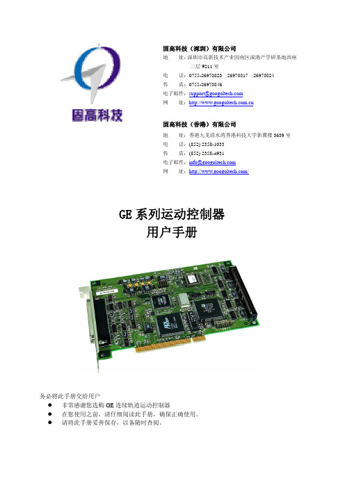
GE系列运动控制器用户手册
第二章
快速使用 ..............................................................5
2.1 开箱检查 ....................................................................................................................................... 5 2.2 GE运动控制器的外形结构 ....................................................................................................... 5 2.2.1 GE-X00-SX运动控制器................................................................................................................ 5 2.3 安装步骤 ......................................................................................................................................... 8
第三章 系统调试 .............................................................22
附录A 技术参数 ...............................................................23
GE Power Steam Power Systems AQCS 产品介绍说明书

GE Powerl e x i b l e S o l u t i o n s f o r I n d u s t r i a l A p p l i c a t i o n sC lean Air For IndustrySTEAM POWER SYSTEMSENVIRONMENTAL CONTROL SOLUTIONSNorth AmericaPower 160 GW Industry360 SystemsLatin AmericaPower 7 GWIndustry230 SystemsEuropePower 113 GWIndustry1,600 SystemsMiddle East and AfricaPower 40 GWIndustry160 SystemsRussia and CISPower 13 GW Industry80 SystemsAsiaPower 98 GWIndustry1,800 SystemsIndiaPower 50 GWIndustry700 SystemsOceaniaPower 20 GWIndustry120 SystemsSYSTEMS (AQCS)Portfolio and OverviewAir Quality Control Systems (AQCS) from GE Power enable you to meet stringent emission regulations for particulate and gaseous pollutants emitted from power plants and industrial operations . The expertise, technology and comprehensive product portfolio provided by Environmental Control Solutions from GE’s Steam Power Systems are adaptable to meet your specific needs for AQCS.Our AQCS technologies are suitable for power generation and industrial applications , including Aluminium, Iron and Steel, Oil and Gas, Cement, Waste-to-Energy, Biomass, Pulp and Paper, and Non-ferrous Metals among others.Our Success:500 GWIn Power Applications5,000Units in Industrial ApplicationsMore than 80 years of experience providing advanced emission controlsSteam Power Systems from GE:• H elps you determine the best combination of technologies for your specific site requirements • O ffers a range of products to cover all types of emissions• D elivers a variety of AQCS for engineering, procurement and construction (EPC) or engineering and procurement (EP)• P rovides after-market services including spare parts, inspection and remote monitoring • O ffers a variety of solutions to upgrade your existing equipment with our latest innovations for improved performance and/or lower operating costsSYSTEMS (AQCS) Customized OfferingsWith Steam Power Systems from GE, customers receive a wealth of air quality control know-how. For new builds as well as upgrades and retrofits of existing AQCS, we offer on-demand solutions tailored to meet your requirements, including partial or full scope:• E ngineering. GE offers advanced air pollution control engineering, from process and equipment design to construction, operations and maintenance.• E quipment supply. Our comprehensive AQCS portfolio of products covers all types of pollutants with advanced technology, using a single process or a combinationto cover the entire flue gas chain. This gives you the flexibility to address complex interactions between components and processes.• C onstruction and commissioning. We offer:— Construction Management— Commissioning Management— Construction & Commissioning Advisory Services• I nspection and maintenance. We provide these servicesfor our own fleet and/or other AQCS.Innovative Products and TechnologiesSince 1983, our technology center in Växjö, Sweden – one of the largest in the world in the field of environmental control solutions – has been at the forefront of advanced research and development for air quality and CO2 control solutions. Focusing on technology innovation and product validation, it has test halls for pilot operations and flow modeling, an analytical laboratory specializing in particle and environmental analyses, an instrument workshop, high voltage facilities for electrostatic precipitator (ESP) testing (switch integrated rectifiers and transformer/rectifier sets), as well as a mechanical workshop for pilot equipment manufacturing.AQCS FOR INDUSTRIAL APPLICATIONSDry ESPParameter NumberApplications Industry, boilers and heaters1Power Capacity (MW/Nm3/h)10 to 1,300Gas Temperatures (°C)70 – 400Gas Flow Rate (m3/s)15 – 2,000Dust Loading at ESP Inlet (g/Nm3)0.2 – 100 g/Nm3; for SDA 600 g/Nm3; for NID 1800 g/Nm3 Emission at ESP Outlet (mg/Nm3)10 – 200 (exceptional 1,000 for ESP as precollector), filterable PM only PM Removal Efficiency Up to 99.95%Availability Up to 98%1I ndustry - Cement: Kiln, Mills, Cooler; Iron and Steel: Sintering, Pelletization, Sponge Iron Kiln, Cast House, Stock House;Fabric FiltersParameter NumberTypes Pulse jet filters and reverse air filters Applications Industry, boilers and heaters1DFGD (NID)Parameter Number SO2 Removal Rate (%)Up to 98DFGD (SDA)Parameter NumberSO2 Removal Rate (%)Up to 95Clean Air for Industry | Flexible AQCS SolutionsWFGD-OSTTypical Information(°C)25-200Up to 250,000Dust Loading at FF inlet (g/Nm3)2–100Emission at FF outlet (mg/Nm3)5-50, filterable PM onlyUp to 99%(°C)70-250Up to 170,000Dust Loading at FF inlet (g/Nm3)1-50Emission at FF outlet (mg/Nm3)Up to 20, filterable PM onlyUp to 98%OTHER AQCS SOLUTIONSMercury, VOC, Zero Liquid DischargeGas Treatment Center – GTCTypical Number CommentCO2 CAPTURE AND UTILIZATION CO2 Capture for Industrial SolutionsPOWER TRANSPORTATION ENERGY MANAGEMENT AVIATION OIL & GAS HEALTHCARE APPLIANCES & LIGHTING Combustion science & services, installedbaseElectrification, controls & power conversiontechnologyServices & technology and is a first-mover in growth regionsRENEWABLE ENERGYClean and productive Wind and Hydro power generationservicesGLOBAL RESEARCH CENTERGLOBAL GROWTH ORGANIZATIONDIGITALCULTURE &SIMPLIFICATIONAdvanced materials & manufacturing, & engineering productivityEngine technology & localization in growth regionsLED is gateway to energy efficiencyDiagnostics technology,is a first-mover &anchor in growthmarketsThe GE StoreDRIVING COMPETITIVE ADVANTAGE ACROSS OUR BUSINESSESWe drive enterprise advantages that benefit the entire company, through what we call the “GE Store.” It means that every business in GE can share and access the same technology, markets, structure and intellect. The value of the GE Store is captured by faster growth at higher margins; it makes the totality of GE more competitive than the parts. No other company has the ability to transfer intellect and technology as GE can through the Store.Steam Power Systems Environmental Control Solutions Clean Air for Industry**************** Trademark of General Electric Company.© 2015, General Electric Company and/or its affiliates. GE Proprietary Information. All RightsReserved. No part of this document may be reproduced, transmitted, stored in a retrieval systemnor translated into any human or computer language, in any form or by any means, electronic,mechanical, magnetic, optical, manual, or otherwise, without the prior written permission of theGeneral Electric Company or its concerned affiliate.Information contained in this document is indicative only. No representation or warranty isgiven or should be relied on that it is complete or correct or will apply to any particular project.This will depend on the technical and commercial circumstances. It is provided without liabilityand is subject to change without notice.GEA32163 (10/2015)。
- 1、下载文档前请自行甄别文档内容的完整性,平台不提供额外的编辑、内容补充、找答案等附加服务。
- 2、"仅部分预览"的文档,不可在线预览部分如存在完整性等问题,可反馈申请退款(可完整预览的文档不适用该条件!)。
- 3、如文档侵犯您的权益,请联系客服反馈,我们会尽快为您处理(人工客服工作时间:9:00-18:30)。
不了此设定值则延时 3 分钟自动进入休眠状态。
F25 减泵频率
有工频泵工作时,当实际频率低于减泵频率,经过
减泵延时 F26 则减掉一工频泵
0-50.0
26.0
F26 减泵延时
功能见 F25 项
0-250
5
当实际压力高 F01+F27 值时,并延时 F29 时间则泄
泄压阀压力控制
F27
压阀打开,当压力小于 F01+0.02 值时,则泄压阀 0-9.99
值变频器输出频率为零
20 Hz
6
F17 超压设定值
实际压力≥F01+F17 时,频率迅速下降,如有工频
0-0.5
0.05
泵运行,则延时 3 秒后减一工频泵
F18 设定压力方式
0:不可以通过操作加﹑减键直接设定压力; 1:可以通过操作加﹑减键直接设定压力
0-1
0
只有在上电正计时时,进入参数设置状态后,此项
1
一、概述 1.1 说明
本手册包含 GE300 系列微机控制器的安装、操作和配置信息。
在使用 GE300 系列微机给水控制器之前,请您仔细阅读本使用说明书,并请妥 善保存。
由于我们始终致力于产品的不断升级和完善,因此,本公司提供的资料如有变 动,恕不另行通知。
1.2 控制器特点 本产品是应广大用户的要求最新推出的高性能微机给水控制器。采用高品
端子功能说明
M1 号变频泵控制端子。直接驱动接触器线圈 M1 号工频泵控制端子。直接驱动接触器线圈 M2 号变频泵控制端子。直接驱动接触器线圈 M2 号工频泵控制端子。直接驱动接触器线圈 M3 号变频泵控制端子。直接驱动接触器线圈 M3 号工频泵控制端子。直接驱动接触器线圈 M4 号变频泵控制端子。直接驱动接触器线圈 备注:GE300BX 型控制器为泄压控制端子 M4 号工频泵控制端子。直接驱动接触器线圈 控制器 AC220V 电源,接火线 控制器 AC220V 电源,接零线 模拟输入信号公共端 模拟输入信号输入端,接远传压力表中心滑动端; 外接 4-20mA 电流信号时,需在 GND 与 IN 端子间跨接 150Ω电阻 模拟供电电源端子,2.5V/20mA 模拟输出信号公共端 模拟输出 0-5V 或 0-10V,用于输出变频器频率给定信号 开关量控制信号公共端 变频器运行信号控制端子 变频器自由停车信号控制端子 变频故障报警端子,当 CT1 与 COM2 短接时,显示 E0,系统运行停止 低水位控制端子,当 CT2 与 COM2 短接时, LD 指示灯亮 双压控制端子,当 CT3 与 COM2 短接时,设定压力显示 F02 的值 消防压力控制端子,当 CT4 与 COM2 短接时,设定压力显示 F02 的值
本控制器采用直插式安装方法,控制器带有回钩,
称
2 R1
3 R2
4 R3
5 R4
6 R5
7 R6
8 R7
9 R8 11 L 12 N 13 GND
14 IN
15 +V 16 COM1 17 D/A 18 COM2 19 FWD 20 FRS 21 CT1 22 CT2 23 CT3 24 CT4
需求。 简化键盘菜单式设定和调整工作状态。 参数在线编程,大大方便使用。 采用开关电源供电设计,具有宽电压适用范围,抗干扰能力强。 器件采用先进的 SMT(表面贴装)工艺,可靠性高。 保护及报警功能齐全,具有变频器故障,远传压力表断线、短路
故障、欠压超时、低水位报警指示。 完善的密码功能。
质元件、材料及融合最新的控制技术而成;和变频器组合在一起,即可构成民用、 工业、消防等行业适用的微机变频调速恒压供水系统。 采用模糊控制原理,自动优化时无需调整控制器参数,响应快、精度高、泵切
换时管网冲击小。 具备自动定时换泵,定时开关机设置,提高水泵平均使用寿命。 系统提供休眠功能节能工作方式。 在压力不足需要加泵时,变频泵将自动降速,减少切换冲击。 增加锅炉补水,泄压阀压力区间控制选择。 变频器故障时,可选择自动转入工频运行。 一用一备、一用一补、两泵、三泵、四泵循环软起等功能,能满足不同用户的
防止水泵频繁起停。当值设为 100 时欠压不加泵, 0-100 0 %
则按定 F00 设定的时间换泵
大则调节快,小则调节慢
1-6
3
防止压力表和传感器失效,压力在此项值以下 2
分钟后产生 E1 报警停机。设为 0 则此项功能无 0-0.2
0
效
系统震动大时,加大此值
0-10
3
填入一数值,可以快速启动水泵,降速时到达此 0-50
数后才可重新工作,当设为 0 此功能无效
0 时钟无效
F34 时钟控制方式
1 F35-F38 有效,即一起一停控制 2 F35-F42 有效,即二起二停控制
0-3
0
3 F35-F46 有效,即三起三停控制
F35 时控 1(小时)
注:
0-23
开
F36 时控 1(分钟)
1 如有消防信号时时控无效
0-59
F37 时控 2(小时)
光耦输出,变 频器急停信号
21 CT1
R2 3
22 CT2
R1 2
23 CT3
1
24 CT4
4
2.5 与常用变频器接线表
微机控制器端子 FWD CM1 CM2 D/A
FUJI 变频器端子 FRD CM GND VS
三肯变频器端子 FR
DCM12 ACM VRF
西门子变频器端子 5 9 4 3
三、 操作与功能参数 3.1 操作各按键名称和功能
3
2.4 标准接线图
电源
控 制 水 泵 启 停 交 流 接 触 器 线 圈
N 12
13 GND
L 11 GE300 14 IN
10
15 +V
远传压力表
R8 9 R7 8 R6 7 R5 6 R4 5 R3 4
16 COM2
0-5v/0-10v
17 D/A
18 COM1 19 FWD 20 FRS
光耦输出,变 频器运行信号
F19 数据初始化
0-1
0
设为 1 则数据初始化,在运行时此项不能修改
实际压力大于“设定压力”-0.02 时,频率小于 F20
F20 休眠频率
时,这种状态保持 F21 时间,则运转信号断开,当 0-50.0
0
F20 为 0 时此功能无效
F21 休眠延时时间
功能见 F20 项
0-999
120
F22 唤醒压力
部件
ESC
名称 编程键
▲
增加键
▼
减小键
SET
切换/存储键
3.2 面板操作说明
功能 进入参数查看、修改状态 退出参数查看、修改状态 功能代码或设定参数值递增 欠压报警时,按压此键可消除报警
功能代码或设定参数值递减
实际压力与输出频率间切换 功能代码与参数递增 存储当前修改的功能代码参数值
HHH 000
HHH 010
–F– 00
–F– XX
–d–XXX
–d–XXX
5
3.3 功能参数
代码
名称
自动定时换泵时 F00
间 F01 设定压力 1
F02 设定压力 2
F03 泵工作方式
F04 第一工作泵 F05 换泵定时器 F06 传感器校零 F07 传感器类型 F08 传感器量程 F09 泵倒换死区时间 F10 输出控制电压
由变频泵停车倒换至工频泵启动的时间
1-10
3秒
0:0-5V 1:0-10V
0-1
1
多台泵工作时,当变频泵运行频率升至 50Hz 时,
经过 F11 时间,实际压力仍小于设定压力,变频 0-250
泵倒为工频运行,下一台变频泵投入运行。欠压
3 15 秒
加泵时间根据系统实际情况设定
在设定压力的正负偏差范围内,不进行加减泵,
0.35
浮动上限
关闭,
F28 工厂设置
F29 泄压阀动作延时
0-60
5
7
F30 工作天数显示
用于查询
天
F31 设定密码
F32
只有密码输入正确才能进入下一项 F33 (工 作天数设定)
0-999 0-999
F33
当实际工作天数等于设定工作天数后 控制
天
可工作天数
器自动停机。须输入正确的密码改变工作天
F44 时控 5(分钟)
0-23
16 小时
0-59
0
分钟
F45 时控 6(小时) 关
F46 时控 6(分钟)
0-23
23 小时
0-59
0
分钟
F47 时钟时位
F48 时钟分位
时钟校准设定
F49 时钟秒位
四、显示项目及故障说明
0-23
小时
0-59
分钟
0-59
秒
显示项目
说明
HHH XX 开机延时正计数,按编程键进入编程状态
当压力小于此值时,经过 F23 延时后运转信号闭
0-9.99
0.15
合,重新启动
F23 唤醒延时
功能见 F22 项
0-250
当休眠条件满足时,为了延长停机时间,将用户设
定压力加增量 F24 作为当前的设定压力,当实际压
F24 休眠前压力增量
0-0.50
0.03
力到达此压力时即进入休眠状态,如实际压力到达
2
二、型号、安装和接线
2.1 型号
两台泵循环软起型:
GE300B
三台泵循环软起型:
GE300C
四台泵循环软起型:
GE300D
两台泵循环软起型(带泄压功能): GE300BX