CORDIC算法VHDL实现
CORDIC算法原理及实现

图4.1 圆坐标系旋转
CORDIC算法原理 --圆坐标系旋转原理
上面的方程组同样可写成矩阵向量形式:
x2 cos y sin 2 sin x1 y cos 1
例如一个90o相移为:
x2 0 1 x1 - y1 y 1 0 y x 1 1 2
x (i 1) x (i ) y (i ) di 2 i y (i 1) y (i ) x (i ) d i 2 i z (i 1) z (i ) d i e (i )
1
z
(0)
通过设定x(0)=1和z(0)=0来计算tan-1y(0)。向量模式 中,判决算子di 满足下面条件:
d i sign ( x (i ) y (i ) )
因此 我们输入x(0)和y(0)(z(0)=0),并通过迭代使y(0) 取值趋近于0。
CORDIC算法原理 --向量模式
CORDIC算法原理 --圆坐标系旋转原理
前面所示的伪旋转现在可以表示为(对每次迭代):
x (i 1) x (i ) d i (2 i y (i ) )
(4.7) 在这里引入第三个方程,被称为角度累加器,用来在 每次迭代过程中追踪累加的旋转角度: z (i 1) z (i ) d i (i ) (4.8) 这里:di=±1。符号di是一个判决算子,用于确定旋转的方向。 上述三个方程式为圆周坐标系中用于角度旋转的CORDIC算法的 表达式。在本章的后续部分中我们还将看到CORDIC算法被用于其 它的坐标系,通过使用这些坐标系可以执行更大范围的函数计算。
CORDIC算法原理 --圆坐标系旋转原理
CORDIC算法VHDL实现
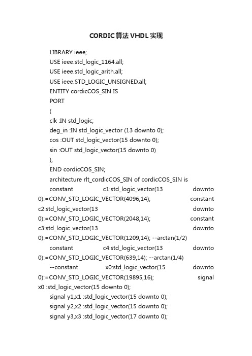
CORDIC算法VHDL实现LIBRARY ieee;USE ieee.std_logic_1164.all;USE ieee.std_logic_arith.all;USE ieee.STD_LOGIC_UNSIGNED.all;ENTITY cordicCOS_SIN ISPORT(clk :IN std_logic;deg_in :IN std_logic_vector (13 downto 0);cos :OUT std_logic_vector(15 downto 0);sin :OUT std_logic_vector(15 downto 0));END cordicCOS_SIN;architecture rlt_cordicCOS_SIN of cordicCOS_SIN isconstant c1:std_logic_vector(13 downto 0):=CONV_STD_LOGIC_VECTOR(4096,14); constant c2:std_logic_vector(13 downto 0):=CONV_STD_LOGIC_VECTOR(2048,14); constant c3:std_logic_vector(13 downto 0):=CONV_STD_LOGIC_VECTOR(1209,14); --arctan(1/2)constant c4:std_logic_vector(13 downto 0):=CONV_STD_LOGIC_VECTOR(639,14); --arctan(1/4)--constant x0:std_logic_vector(15 downto 0):=CONV_STD_LOGIC_VECTOR(19895,16); signal x0 :std_logic_vector(15 downto 0);signal y1,x1 :std_logic_vector(15 downto 0);signal y2,x2 :std_logic_vector(15 downto 0);signal y3,x3 :std_logic_vector(17 downto 0);signal y4,x4 :std_logic_vector(19 downto 0);signal p1,p2,p3,p4 :std_logic_vector(13 downto 0);beginx0 <= conv_std_logic_vector(26980,16);---------------------------------step 1------------------------------------ process(clk)beginif rising_edge(clk) thenif deg_in(13) ='1' theny1 <= x"0000" -x0;elsey1 <= x0;end if;end if;end process;process(clk)beginif rising_edge(clk) thenx1 <=(others =>'0');end if;end process;process(clk)beginif rising_edge(clk) thenif deg_in(13) ='1' thenp1 <= deg_in + c1;elsep1 <= deg_in - c1;end if;end if;end process;---------------------------------step 2------------------------------------ process(clk)beginif rising_edge(clk) thenif p1(13) ='1' theny2 <= y1 - x1;elsey2 <= y1 + x1;end if;end if;end process;process(clk)beginif rising_edge(clk) thenif p1(13) ='1' thenx2 <= x1 + y1;elsex2 <= x1 - y1;end if;end if;end process;process(clk)beginif rising_edge(clk) thenif p1(13) ='1' thenp2 <= p1 + c2;elsep2 <= p1 - c2;end if;end process;---------------------------------step 3------------------------------------ process(clk)beginif rising_edge(clk) thenif p2(13) ='1' theny3 <= (y2(15) & y2 &'0') -(x2(15) & x2(15) & x2);elsey3 <= (y2(15) & y2 &'0') + (x2(15) & x2(15) & x2);end if;end if;end process;process(clk)beginif rising_edge(clk) thenif p2(13) ='1' thenx3 <= (x2(15) & x2 & '0') + (y2(15) & y2(15) & y2 );elsex3 <= (x2(15) & x2 & '0') - (y2(15) & y2(15) & y2 );end if;end if;end process;process(clk)beginif rising_edge(clk) thenif p2(13) ='1' thenp3 <= p2 + c3;elsep3 <= p2 - c3;end if;end process;---------------------------------step 4------------------------------------ process(clk)beginif rising_edge(clk) thenif p3(13) ='1' theny4 <= (y3 & "00") -(x3(17) & x3(17) & x3);elsey4 <= (y3 & "00") +(x3(17) & x3(17) & x3);end if;end if;end process;process(clk)beginif rising_edge(clk) thenif p3(13) ='1' thenx4 <= (x3 & "00") + (y3(17) & y3(17) & y3 );elsex4 <= (x3 & "00") - (y3(17) & y3(17) & y3 );end if;end if;end process;process(clk)beginif rising_edge(clk) thenif p3(13) ='1' thenp4 <= p3 + c4;elsep4 <= p3 - c4;end if;end if;end process;cos<=x4(19 downto 4); sin<=y4(19 downto 4); end rlt_cordicCOS_SIN;。
正交信号发生器的FPGA设计与仿真
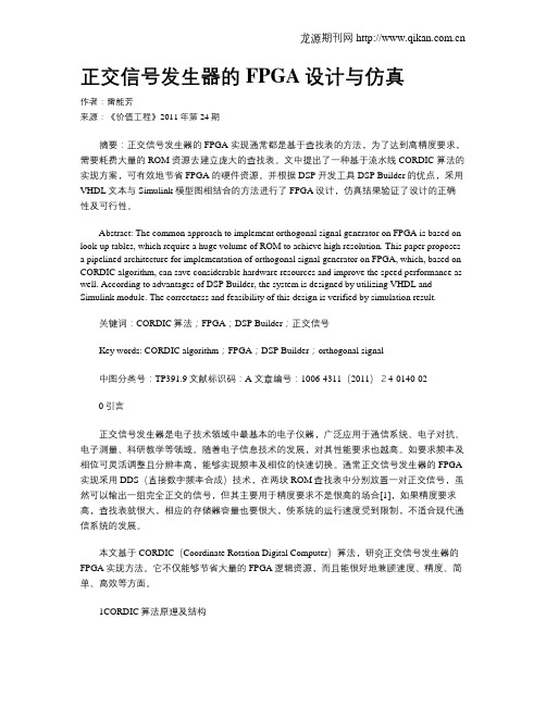
正交信号发生器的FPGA设计与仿真作者:雷能芳来源:《价值工程》2011年第24期摘要:正交信号发生器的FPGA 实现通常都是基于查找表的方法,为了达到高精度要求,需要耗费大量的ROM 资源去建立庞大的查找表。
文中提出了一种基于流水线CORDIC 算法的实现方案,可有效地节省FPGA 的硬件资源。
并根据DSP 开发工具DSP Builder的优点,采用VHDL文本与Simulink 模型图相结合的方法进行了FPGA设计,仿真结果验证了设计的正确性及可行性。
Abstract: The common approach to implement orthogonal signal generator on FPGA is based on look-up tables, which require a huge volume of ROM to achieve high resolution. This paper proposes a pipelined architecture for implementation of orthogonal signal generator on FPGA, which, based on CORDIC algorithm, can save considerable hardware resources and improve the speed performance as well. According to advantages of DSP Builder, the system is designed by utilizing VHDL and Simulink module. The correctness and feasibility of this design is verified by simulation result.关键词:CORDIC算法;FPGA;DSP Builder;正交信号Key words: CORDIC algorithm;FPGA;DSP Builder;orthogonal signal中图分类号:TP391.9文献标识码:A 文章编号:1006-4311(2011)24-0140-020引言正交信号发生器是电子技术领域中最基本的电子仪器,广泛应用于通信系统、电子对抗、电子测量、科研教学等领域。
实验7 Cordic 算法实现
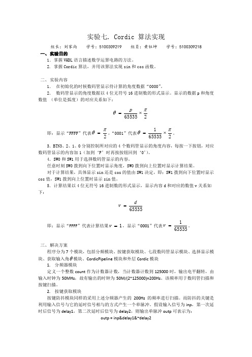
实验七. Cordic 算法实现组长:刘家尚 学号:5100309219 组员:黄钰坤 学号:5100309218一、 实验目的1.掌握VHDL 语言描述数学运算电路的方法。
2. 掌握Cordic 算法,并用该算法实现sin 和cos 函数。
二、 实验内容1. 在初始化的时候数码管显示待计算的角度数据“0000”。
2. 数码管显示的角度数据以4位无符号16进制数的形式显示。
显示的数据p 和角度数值 (单位是弧度)的对应关系如下:265535πθ⨯=p 即:显示“FFFF ”代表2πθ=,“0001”代表2655351πθ⨯=。
3.BTN3、2、1、0分别控制所对应的4个数码管显示的角度内容,每按一下按钮,对应数码管显示的内容加1(加到‘F ’时再按按钮回到‘0’)。
4.SW0和SW1用于选择数码管显示的内容。
任意时刻SW0拨到向下位置时显示角度,SW0拨到向上位置时显示计算结果。
对于计算结果,具体显示sin 还是cos 的值由SW1决定,即:SW1拨到向下位置时显示cos 值,SW1拨到向上位置时显示sin 值。
5.计算结果以4位无符号16进制数的形式显示,显示内容d 和对应的数值v 关系如下:65535dv =即:显示“FFFF ”代表计算结果1=v ,显示“0001”代表655351=v 。
三、 解决方案程序分为7个模块,包括分频模块、按键获取模块、七段数码管显示模块、选择显示模块、获取输入角θ模块、CordicPipeline 模块和外层Cordic 模块1. 分频器模块定义一个整数count 作为计数器计数,当计数器计数到125000时,输出电平翻转,由输入时钟为50MHz ,故有输出的时钟为50M/(2*125000)=200Hz 。
该频率用于数码管扫描和按键扫描。
2. 按键获取模块按键防抖模块同样的采用上述分频器产生的200Hz 的频率进行扫描。
而防抖的关键是利用输入信号与它的延时信号相与的方式产生一个单脉冲。
基于FPGA的CORDIC算法实现
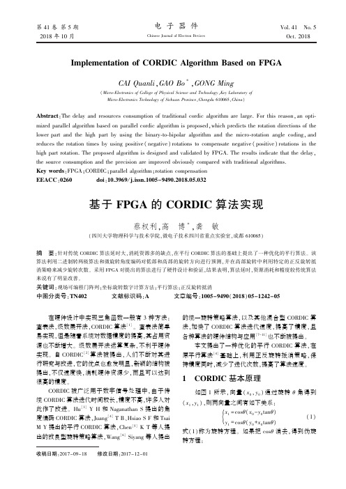
关键词:现场可编程门阵列ꎻ坐标旋转数字计算方法ꎻ平行算法ꎻ正反旋转抵消 中图分类号:TN402 文献标识码:A 文章编号:1005-9490(2018)05-1242-05
在硬件设计中实现三角函数一般有 3 种方法: 查表法ꎬ级数展开法ꎬCORDIC 算法[1] ꎮ 查表法简单 易实现ꎬ但是随着系统对数据精度的提高ꎬ其占用资 源也不断增大ꎮ 级数展开法运算复杂ꎬ不利于硬件 实现ꎮ 自 CORDIC[2] 算法被提出ꎬ人们不断对其进 行研究与改进ꎬ它的优点也愈发明显ꎬ新颖的结构被 提出ꎬ不仅速度快ꎬ消耗硬件资源少ꎬ而且可以达到 很高的精度ꎮ
第5期
蔡权利ꎬ高 博等:基于 FPGA 的 CORDIC 算法实现
{x1 = x0 -y0tanθ y1 = y0 +x0 tanθ
(2)
12 43
图 1 CORDIC 向量旋转示意图
CORDIC 算法思想是利用 2-i 近似 tanθi ꎬ来实现
三角函数的计算ꎮ
当使用 2-i 近似 tanθi ꎬ从而每次的旋转角度为
Abstract:The delay and resources consumption of traditional cordic algorithm are large. For this reasonꎬan opti ̄ mized parallel algorithm based on parallel cordic algorithm is proposedꎬwhich predicts the rotation directions of the lower part and the high part by using the binary ̄to ̄bipolar algorithm and the micro ̄rotation angle codingꎬ and reduces the rotation times by using positive ( negative) rotations to compensate negative ( positive) rotations in the high part rotation. The proposed algorithm is designed and validated by FPGA. The results indicate that the delayꎬ the source consumption and the precision are improved obviously compared with traditional algorithms. Key words:FPGAꎻCORDICꎻparallel algorithmꎻrotation compensation EEACC:0260 doi:10.3969 / j.issn.1005-9490.2018.05.032
cordic算法求角度的verilog实现
cordic算法求角度的verilog实现1. 引言1.1 概述本篇文章旨在探讨并介绍Cordic算法在Verilog中的实现方式。
Cordic算法是一种用于计算三角函数和超越函数的快速算法,它具备较高的精度和计算效率,被广泛应用于数字信号处理、通信系统等领域。
1.2 文章结构文章将按照以下顺序进行介绍:首先,对Cordic算法进行概述,包括原理介绍、应用领域以及优势与局限性。
接着,在第三部分中详细解释了Verilog实现Cordic算法的设计思路和步骤。
随后,在第四部分中对该设计进行功能验证和性能评估,探究其计算准确性和速度。
最后,在第五部分对结果进行总结和讨论,并提出改进之处和未来发展方向建议。
1.3 目的本文主要目的有两个方面:一方面是介绍Cordic算法作为一种高效计算角度的方法,对其原理进行深入剖析并说明其应用范围与局限性;另一方面是通过使用Verilog语言实现Cordic算法,展示其在硬件电路设计中的具体应用,并评估其功能和性能。
通过本文的介绍,读者可以了解Cordic算法的基本原理及其在Verilog中的实现方式,同时对其优势与限制有更深入的认识。
此外,读者也可以通过作者对功能验证和性能评估结果的分析,对该算法在实际应用中的表现有更清晰的认识。
最后,读者可以从结论与展望部分中获得未来改进该算法以及相关硬件电路设计发展方向的建议。
2. Cordic算法概述:2.1 原理介绍:Cordic算法,全称为Coordinate Rotation Digital Computer算法,是一种用于计算各种三角函数(如正弦、余弦、正切)的迭代近似方法。
该算法基于旋转操作,通过一系列迭代步骤逐渐逼近所需的角度值。
Cordic算法最初由Volder在1959年提出,并被广泛应用于计算机领域中需要高效计算三角函数的场景。
其核心思想是将复杂的三角运算转化为一系列简单的位移、加减和比较等基本操作,从而实现了高速且低资源消耗的计算。
流水线CORDIC算法的FPGA实现
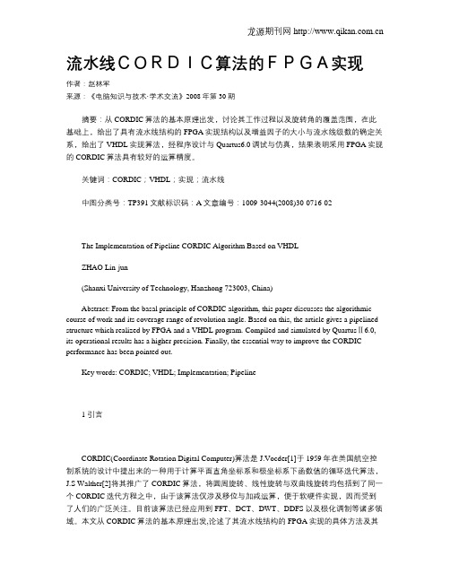
流水线CORDIC算法的FPGA实现作者:赵林军来源:《电脑知识与技术·学术交流》2008年第30期摘要:从CORDIC算法的基本原理出发,讨论其工作过程以及旋转角的覆盖范围,在此基础上,给出了具有流水线结构的FPGA实现结构以及增益因子的大小与流水线级数的确定关系,给出了VHDL实现算法,经程序设计与Quartus6.0调试与仿真,结果表明采用FPGA实现的CORDIC算法具有较好的运算精度。
关键词:CORDIC;VHDL;实现;流水线中图分类号:TP391文献标识码:A文章编号:1009-3044(2008)30-0716-02The Implementation of Pipeline CORDIC Algorithm Based on VHDLZHAO Lin-jun(Shanxi University of Technology, Hanzhong 723003, China)Abstract: From the basal principle of CORDIC algorithm, this paper discusses the algorithmic course of work and its coverage range of revolution angle. Based on this, the article gives a pipelined structure which realized by FPGA and a VHDL program. Compiled and simulated by QuartusⅡ6.0, its operational results has a higher precision. Finally, the essential way to improve the CORDIC performance has been pointed out.Key words: CORDIC; VHDL; Implementation; Pipeline1 引言CORDIC(Coordinate Rotation Digital Computer)算法是J.Vocder[1]于1959年在美国航空控制系统的设计中提出来的一种用于计算平面直角坐标系和极坐标系下函数值的循环迭代算法,J.S Walther[2]将其推广了CORDIC算法,将圆周旋转、线性旋转与双曲线旋转均包括到了同一个CORDIC迭代方程之中,由于该算法仅涉及移位与加减运算,便于软硬件实现,因而受到了人们的广泛关注。
针对正弦余弦计算的CORDIC算法优化及其FPGA实现

直接数字频率合成器是现代频率合成的主要工具,它有频率分辨率高,频率转化快等众多优点。这种器件被广泛应用于众多领域。
在CORDIC算法中,对数据的操作只有移位和加/减,易于用硬件实现的。而且CORDIC算法也容易流水线实现,可以在计算系统中的高速进行。
本文链接:/Thesis_Y1325245.aspx
授权使用:武汉大学(whdx),授权号:a42506fa-e993-4c54-b65b-9e4501376a91
下载时间:2010年12月7日
对于Jacobi算法的硬件实现,论文经过分析总结提出了两种大的结构:串行计算机构和并行计算结构。串行计算结构又根据具体计算过程的不同分成了两种方法,一种方法是先寻找矩阵非对角元素的最大元,然后对其相应的行列进行Jacobi旋转;另一种方法是通过遍历的方法来对矩阵的行列依次进行Jacobi旋转。并行计算结构是一种阵列型的结构,它由对角线处理单元和非对角线处理单元通过一定的连接组成,每个处理单元处理四个矩阵元素,在一次处理后跟相邻的单元进行数据交换进行新的一次计算。
2.会议论文肖顺文.陈亚军CORDIC算法的优化设计及其FPGA实现2007
针对采用流水结构实现CORDIC算法存在的不足,从旋转角度范围、旋转角度精度的调整、模校正因子的分解三个方面进行了详细的分析,并给出了相应的优化和改进措施;实现了CORDIC算法的全流水结构,并用CORDIC算法实现信号发生器加以验证。
设计以Altera CycloneⅡ EP2C35F672C8为目标器件,对算法的实现电路进行功能和时序仿真。仿真结果表明,算法电路有较高的转换精度和较高的运算速度,其中坐标转换模块的时钟频率达到130MHz,信号处理模块的时钟频率达到140MHz。最后,在FPGA硬件平台上对数字图像旋转引擎进行了整体验证。图像的输入信号取自 PC机的 VGA信号接口,处理后的图像输出液晶显示器的VGA信号接口。验证的结果显示,数字图像旋转引擎所处理的图像清晰稳定,能设定旋转角度、旋转方向和缩放比例,实现自如流畅的动态画面旋转和缩放。
- 1、下载文档前请自行甄别文档内容的完整性,平台不提供额外的编辑、内容补充、找答案等附加服务。
- 2、"仅部分预览"的文档,不可在线预览部分如存在完整性等问题,可反馈申请退款(可完整预览的文档不适用该条件!)。
- 3、如文档侵犯您的权益,请联系客服反馈,我们会尽快为您处理(人工客服工作时间:9:00-18:30)。
LIBRARY ieee;
USE ieee.std_logic_1164.all;
USE ieee.std_logic_arith.all;
USE ieee.STD_LOGIC_UNSIGNED.all;
ENTITY cordicCOS_SIN IS
PORT
(
clk :IN std_logic;
deg_in :IN std_logic_vector (13 downto 0);
cos :OUT std_logic_vector(15 downto 0);
sin :OUT std_logic_vector(15 downto 0)
);
END cordicCOS_SIN;
architecture rlt_cordicCOS_SIN of cordicCOS_SIN is
constant c1:std_logic_vector(13 downto 0):=CONV_STD_LOGIC_VECTOR(4096,14); constant c2:std_logic_vector(13 downto 0):=CONV_STD_LOGIC_VECTOR(2048,14); constant c3:std_logic_vector(13 downto 0):=CONV_STD_LOGIC_VECTOR(1209,14); --arctan(1/2)
constant c4:std_logic_vector(13 downto 0):=CONV_STD_LOGIC_VECTOR(639,14); --arctan(1/4)
--constant x0:std_logic_vector(15 downto 0):=CONV_STD_LOGIC_VECTOR(19895,16); signal x0 :std_logic_vector(15 downto 0);
signal y1,x1 :std_logic_vector(15 downto 0);
signal y2,x2 :std_logic_vector(15 downto 0);
signal y3,x3 :std_logic_vector(17 downto 0);
signal y4,x4 :std_logic_vector(19 downto 0);
signal p1,p2,p3,p4 :std_logic_vector(13 downto 0);
begin
x0 <= conv_std_logic_vector(26980,16);
---------------------------------step 1------------------------------------ process(clk)
begin
if rising_edge(clk) then
if deg_in(13) ='1' then
y1 <= x"0000" -x0;
else
y1 <= x0;
end if;
end if;
end process;
process(clk)
begin
if rising_edge(clk) then
x1 <=(others =>'0');
end if;
end process;
process(clk)
begin
if rising_edge(clk) then
if deg_in(13) ='1' then
p1 <= deg_in + c1;
else
p1 <= deg_in - c1;
end if;
end if;
end process;
---------------------------------step 2------------------------------------ process(clk)
begin
if rising_edge(clk) then
if p1(13) ='1' then
y2 <= y1 - x1;
else
y2 <= y1 + x1;
end if;
end if;
end process;
process(clk)
begin
if rising_edge(clk) then
if p1(13) ='1' then
x2 <= x1 + y1;
else
x2 <= x1 - y1;
end if;
end if;
end process;
process(clk)
begin
if rising_edge(clk) then
if p1(13) ='1' then
p2 <= p1 + c2;
else
p2 <= p1 - c2;
end if;
end if;
end process;
---------------------------------step 3------------------------------------ process(clk)
begin
if rising_edge(clk) then
if p2(13) ='1' then
y3 <= (y2(15) & y2 &'0') -(x2(15) & x2(15) & x2);
else
y3 <= (y2(15) & y2 &'0') + (x2(15) & x2(15) & x2);
end if;
end if;
end process;
process(clk)
begin
if rising_edge(clk) then
if p2(13) ='1' then
x3 <= (x2(15) & x2 & '0') + (y2(15) & y2(15) & y2 );
else
x3 <= (x2(15) & x2 & '0') - (y2(15) & y2(15) & y2 );
end if;
end if;
end process;
process(clk)
begin
if rising_edge(clk) then
if p2(13) ='1' then
p3 <= p2 + c3;
else
p3 <= p2 - c3;
end if;
end if;
end process;
---------------------------------step 4------------------------------------ process(clk)
begin
if rising_edge(clk) then
if p3(13) ='1' then
y4 <= (y3 & "00") -(x3(17) & x3(17) & x3);
else
y4 <= (y3 & "00") +(x3(17) & x3(17) & x3);
end if;
end if;
end process;
process(clk)
begin
if rising_edge(clk) then
if p3(13) ='1' then
x4 <= (x3 & "00") + (y3(17) & y3(17) & y3 );
else
x4 <= (x3 & "00") - (y3(17) & y3(17) & y3 );
end if;
end if;
end process;
process(clk)
begin
if rising_edge(clk) then
if p3(13) ='1' then
p4 <= p3 + c4;
else
p4 <= p3 - c4;
end if;
end if;
end process;
cos<=x4(19 downto 4);
sin<=y4(19 downto 4);
end rlt_cordicCOS_SIN;。