英专说明文翻译-甲基硅酸钠-防水剂
甲基硅酸钠
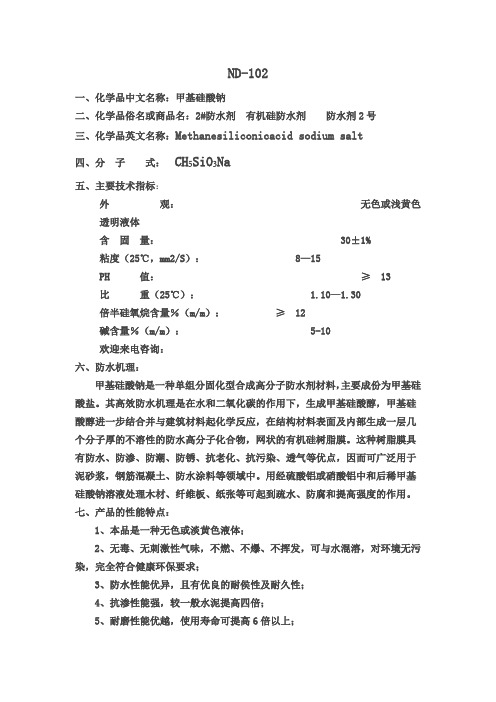
ND-102一、化学品中文名称:甲基硅酸钠二、化学品俗名或商品名:2#防水剂有机硅防水剂防水剂2号三、化学品英文名称:Methanesiliconicacid sodium salt四、分子式:CH₅SiO₃Na五、主要技术指标:外观:无色或浅黄色透明液体含固量:30±1%粘度(25℃,mm2/S):8—15PH 值:≥13比重(25℃): 1.10—1.30倍半硅氧烷含量%(m/m):≥12碱含量%(m/m):5-10欢迎来电咨询:六、防水机理:甲基硅酸钠是一种单组分固化型合成高分子防水剂材料,主要成份为甲基硅酸盐。
其高效防水机理是在水和二氧化碳的作用下,生成甲基硅酸醇,甲基硅酸醇进一步结合并与建筑材料起化学反应,在结构材料表面及内部生成一层几个分子厚的不溶性的防水高分子化合物,网状的有机硅树脂膜。
这种树脂膜具有防水、防渗、防潮、防锈、抗老化、抗污染、透气等优点,因而可广泛用于泥砂浆,钢筋混凝土、防水涂料等领域中。
用经硫酸铝或硝酸铝中和后稀甲基硅酸钠溶液处理木材、纤维板、纸张等可起到疏水、防腐和提高强度的作用。
七、产品的性能特点:1、本品是一种无色或淡黄色液体;2、无毒、无刺激性气味,不燃、不爆、不挥发,可与水混溶,对环境无污染,完全符合健康环保要求;3、防水性能优异,且有优良的耐侯性及耐久性;4、抗渗性能强,较一般水泥提高四倍;5、耐磨性能优越,使用寿命可提高6倍以上;6、具有钝化作用,对钢筋无锈蚀;7、施工安全简便,造价合理。
八、适合范围1、广泛适用于屋面、内外墙面、地面、卫生间、厨房、地下室和仓库的防水防潮以及钢筋混凝土结构的阻透防渗透;2、用于地下人防工程:如涵洞、桥梁、堤坝、隧道、大型水电站、引水工程,以减少水侵蚀,防止风化;3、用于各种水池:如游泳池、净水池、污水池、水塔等;4、用于高吸水无机聚集体:如珍珠岩板、屋面砖、水泥砖、高层建筑轻体砖饰面、石棉、无机织物、保温材料等的浸渍,使之具有显著的防水、防潮效果;5、用于水溶性建筑涂料的防水、保护色彩、防止污染、防止老化,已广泛用于外墙饰面;6、用于乳胶漆、水玻璃、107胶的添加剂,能使其具有明显的增水性,并可保持稳定的粘结强度;7、用于石油钻井,可调节泥浆粘度和密度,可有效防止钻井塌陷提高钻井率;8、用于油井后期开泵、注入采油层,防止采油层地壳骨架塌陷,使得距油井较远的石油比较顺利开采;9、用于其它以减少吸水性及抗渗防水的特殊用途。
专业英语 (Supplementary Material)

• 22. Titanium(钛),元素符号 Ti ( ),元素符号 • 德国科学家克拉普罗特根据希腊神话故事中由天 王(Uranus)和地母(Gaea)的巨人儿子泰坦 )和地母( ) Titan的名字命名了这个元素。 的名字命名了这个元素。 的名字命名了这个元素 • 23. Vanadium(钒),元素符号 V ( ),元素符号 • 1830年由瑞典化学家塞夫斯特穆发现,并以斯堪 年由瑞典化学家塞夫斯特穆发现, 年由瑞典化学家塞夫斯特穆发现 的纳维亚神话中的女神凡娜蒂斯命名。 的纳维亚神话中的女神凡娜蒂斯命名。
• 18. Argon(氩),元素符号 Ar ( ),元素符号 • 氩(argon)是希腊语的“工作”(ergon 是称 )是希腊语的“工作” 为尔格的能量单位)。 为尔格的能量单位)。 • 19. Potassium(钾),元素符号 K ( ),元素符号 • 钾的英文名称是戴维根据 potash(草木灰)加 (草木灰) ium 组合而成的,potash 是 pot (壶和 ash (灰) 组合而成的, 壶和) 壶和 灰 的合成词。 的合成词。钾的元素符号取自拉丁文名 kalium
• 3. Lithium(锂),元素符号 Li ( ),元素符号 • 1817年,瑞典化学家 Arfvedson 从透锂长石中发 年 现一种新元素,用希腊语石头 lithos 命名。 现一种新元素, 命名。 • 4. Beryllium(铍),元素符号 Be ( ),元素符号 • 铍作为绿柱石的成分天然存在,德国人克拉普罗 铍作为绿柱石的成分天然存在, 的名字将其命名。 特按绿柱石 beryl 的名字将其命名。 • 5. Boron(硼),元素符号 B ( ),元素符号 • 因为硼砂白色透明,英国人戴维按阿拉伯语和波 因为硼砂白色透明,
化学名称英语互译

使用卡Dear Sir or MadamW e have obtained your name and address from InternetW e would like to take this opportunity to introduce our company and products, with the hope that we may work together with you in the future.W e are factory specializing in the manufacture and export of chemical material. To give you a general idea of our products, we are enclosing our catalogue for your referenceInorganic Chemical Products: 无机化学产品1. Calcium Chloride 氯化钙2. Sodium Formate 甲酸钠3. Sodium Sulphate 硫酸钠元明粉芒硝4. Sodium Hexametaphosphate 六偏磷酸钠5. Sodium Meterbisulphite6. Sodium Tripolyphosphate 三聚磷酸钠三磷酸钠7. Zinc Oxide 氧化锌8. PAC 聚合氧化铝聚氧化铝9. Aluminium Sulphate 硫酸铝10. Caustic soda 苛性钠氧化钠11. Soda ash 碳酸钠苏打粉12. Barium sulfate 硫酸钡13. Zinc Sulphate 硫酸锌14. Potassium Carbonate 碳酸钾Organic Chemical products: 有机化学产品1. Carboxyl Methyl Cellulose 甲基纤维素2. Formic Acid 甲酸蚁酸3. Oxalic Acid 草酸4. Pentaerythritol 季戊四醇5. Glacial Acetic Acid 冰醋酸冰乙酸6. LABSA 烷基苯磺酸Pigment &Dyestuff: 颜料和染料1. Lithopone 锌钡白2. Sulphur Black 硫磺黑3. Titanium Dioxide 二氧化钛4. Chrome Oxide Green 氧化格绿5. Carbon black 炭黑Feedstuff 饲料Zinc Oxide 氧化锌Should any of these items be of interest to you, please let us know. W e will be happy to give you a quotation upon receipt of your detailed requirementsI look forward to your early reply.Best wishes.AnnaMSN suxiaocui19880513@语言格式Dear my friendHow is your business goingW e are one of biggest manufacturers and exporters in china, we have the chemicals as follows:Detergent chemicals industry 清洁剂化学1. Sodium Tripolyphosphate2. Caustic soda3. LABSA4. SLES 十二烷基醚硫酸钠W ater treatment chemicals industry 水处理化学1.PAC2.Aluminium Sulphate3.Polyacrylamide (PAM) 聚丙烯酰胺4.Actived Carbon 活跃碳Textile chemicals industry 纺织化学产品1. Formic acid2. Glacial acetic acid3. Sodium formate4. Hydrogen peroxide 过氧化氢Paint chemicals industry 颜料化学1. Titanium dioxide2. Lithopone3. Zinc oxide4. Iron oxide5. Chrome Oxide GreenNew chemicals 新化学产品1.paraffin wax 固体石蜡2.calcium carbide 碳化钙3.glycerin 甘油4.boric acid 硼酸5.EDTA 乙二胺四乙酸6.potassium carbonate 碳酸钾7.gum rosin 松香8.perchloroethylene 全氯乙烯9.Zinc Sulphate 硫酸锌10.butyl acrylate 丙烯酸乙酯11.ethyl acrylate 丙烯酸乙酯If you have any enquiries, please feel free tocontact me, I will try my best to help youSincerely hope I could have the chance to be your business partnerW ait for your early good newsThanks & best regardsCindyMSN:cindy_fuyin@报盘Dear Sir or Madam:Thank you for your inquiry about our products. I hope we can conclude some deals with you in the near future.Our best prices as follows:Product name: Sodium Formate 95% Price: USD350 /MT CIF NHA V A SHEV A Packing: 25kg in the PP woven bag, 25MT in the 20’FCLPayment: T/T or L/Cat sightDelivery: Within 2-3weeks after receiving your prepayment or workable L/CV alidity: 7 daysIf you have any questions, please tell me immediately. I will do my best to meet your requirements. Our goods are popular in the world due to its good quality.I look forward to your early reply.Y ours sincerely Anna尊敬的先生或女士:感谢您对我们的产品的询问。
models for the structure of C-S-H- applicability to hardened pastes of tricalcium silicate

Tobermorite/jennite-and tobermorite/calcium hydroxide-based models for the structure of C-S-H:applicability to hardened pastes of tricalcium silicate,h -dicalcium silicate,Portland cement,and blends of Portlandcement with blast-furnace slag,metakaolin,or silica fumeI.G.Richardson *Civil Engineering Materials Unit,School of Civil Engineering,University of Leeds,Leeds LS29JT,UKReceived 26May 2004;accepted 27May2004AbstractThe purpose of this article is to discuss the applicability of the tobermorite–jennite (T/J)and tobermorite–‘solid-solution’calcium hydroxide (T/CH)viewpoints for the nanostructure of C-S-H present in real cement pastes.The discussion is facilitated by a consideration of the author’s 1992model,which includes formulations for both structural viewpoints;its relationship to other recent models is outlined.The structural details of the model are clearly illustrated with a number of schematic diagrams.Experimental observations on the nature of C-S-H present in a diverse range of cementitious systems are considered.In some systems,the data can only be accounted for on the T/CH structural viewpoint,whilst in others,both the T/CH and T/J viewpoints could apply.New data from transmission electron microscopy (TEM)are presented.The ‘inner product’(Ip)C-S-H in relatively large grains of C 3S or alite appears to consist of small globular particles,which are c 4–8nm in size in pastes hydrated at 20j C but smaller at elevated temperatures,c 3–4nm.Fibrils of ‘outer product’(Op)C-S-H in C 3S or h -C 2S pastes appear to consist of aggregations of long thin particles that are about 3nm in their smallest dimension and of variable length,ranging from a few nanometers to many tens of nanometers.The small size of these particles of C-S-H is likely to result in significant edge effects,which would seem to offer a reasonable explanation for the persistence of Q 0(H)species.This would also explain why there is more Q 0(H)at elevated temperatures,where the particles seem to be smaller,and apparently less in KOH-activated pastes,where the C-S-H has foil-like morphology.In blended cements,a reduction in the mean Ca/Si ratio of the C-S-H results in a change from fibrillar to a crumpled-foil morphology,which suggests strongly that as the Ca/Si ratio is reduced,a transition occurs from essentially one-dimensional growth of the C-S-H particles to two-dimensional;i.e.,long thin particles to foils.Foil-like morphology is associated with T-based structure.The C-S-H present in small fully hydrated alite grains,which has high Ca/Si ratio,contains a less dense product with substantial porosity;its morphology is quite similar to the fine foil-like Op C-S-H that forms in water-activated neat slag pastes,which has a low Ca/Si ratio.It is thus plausible that the C-S-H in small alite grains is essentially T-based (and largely dimeric).Since entirely T-based C-S-H is likely to have different properties to C-S-H consisting largely of J-based structure,it is possible that the C-S-H in small fully reacted grains will have different properties to the C-S-H formed elsewhere in a paste;this could have important implications.D 2004Elsevier Ltd.All rights reserved.Keywords:Calcium-silicate-hydrate (C-S-H);Cement paste;Granulated blast-furnace slag;Metakaolin;Silica fume1.IntroductionWhat is it that is produced during the hydration of Portland cement (PC)that results in the formation of a hardened mass?This rather fundamental question was first addressed experimentally by Henri Le Chatelier and Wil-helm Michae ¨lis in their classic works of the late 19th andearly 20th centuries.Their competing theories for the hardening of cement resulted in a long-continued and somewhat polarized debate:Michae ¨lis’‘colloids’theory (e.g.,Refs.[1,2])(and its derivatives, e.g.,Ref.[3]),against Le Chatelier’s ‘crystalloids’theory (e.g.,Refs.[4,5]).Le Chatelier believed that the principal binding phase was a calcium silicate hydrate of formula CaO ÁSiO 2Á2.5H 2O;Newberry and Smith [6]also thought that it was a calcium silicate hydrate,but with the formula 1.5–2CaO ÁSiO 2Á(aq),whilst Rankin [7]thought it a0008-8846/$–see front matter D 2004Elsevier Ltd.All rights reserved.doi:10.1016/j.cemconres.2004.05.034*Tel.:+44-113-343-2331;fax:+44-113-343-2265.E-mail address:i.g.richardson@ (I.G.Richardson).Cement and Concrete Research 34(2004)1733–1777hydrous silica.Bogue concluded in his book in 1955that the probable composition was close to 1.5CaO ÁSiO 2Á(aq)[8].Bernal et al.[9]found through X-ray studies on hydrated C 3S pastes that the calcium silicate hydrate (C-S-H)that was formed was nearly amorphous and thus difficult to characterize structurally;they did,however,consider that it was related to C-S-H phases formed in dilute suspensions,which they called calcium silicate hydrates (I)and (II)[10],which had low and high Ca/Si ratios,respectively.Calcium silicate hydrate (I)had a layer structure,with the layers elongated in one direction that resulted in a fibrous structure,and showed similarities to tobermorite,a rare crystalline calcium silicate hydrate that had been found in Northern Ireland,which has the approx-imate constitutional formula Ca 4(Si 6O 18H 2)ÁCa Á4H 2O and a Ca/Si ratio of 0.83.Its structure—first described by Megaw and Kelsey in 1956[11]—contains linear silicate chains of the ‘dreierkette’form in which the silicate tetrahedra coordinate themselves to Ca 2+ions by linking in such a way as to repeat a kinked pattern after every three tetrahe-dra.Two of the three tetrahedra share O–O edges with the central Ca–O part of the layer;these are linked together and are often referred to as ‘paired’tetrahedra (P).The third tetrahedron,which shares an oxygen atom at the pyramidal apex of a Ca polyhedron,connects the two ‘paired’tetrahedra and so is termed ‘bridging’(B).The dreierkette-type chain present in tobermorite is illustrated in Fig.1.Taylor and Howison [13]suggested that the Ca/Si ratio could be raised above 0.83by the removal of some of these ‘bridging’tetrahedra and replaced by interlayer Ca 2+ions.Various dreierkette-based models have subsequently been proposed,which broadly fall into two categories that have different ways of raising the Ca/Si ratio to the value observed experimentally in C 3S or neat PC pastes,i.e.,1.7–1.8.The first category envisages elements of tober-morite-like structure interstratified with layers of calcium hydroxide:the so-called tobermorite–‘solid-solution’calci-um hydroxide,or T/CH,viewpoint [14–16].The second category envisages elements of tobermorite-like structure intermixed with others of jennite-like structure [17]:the tobermorite–jennite,or T/J,viewpoint.Jennite is another crystalline calcium silicate hydrate that has dreierkette silicate chains,but it has a much higher Ca/Si ratio than tobermorite (formula Ca 9Si 6O 18(OH)6Á8H 2O;Ca/Si ratioofFig.1.Schematic diagrams showing dreierkette chains present in 14A˚tobermorite (which in theory are of infinite length)projected along [010](top)and [210](crystal structure data from Bonaccorsi et al.[12]and private communication).The chains have a kinked pattern where some silicate tetrahedra share O –O edges with the central Ca –O layer (called ‘paired’tetrahedra,P)and others that do not (called ‘bridging’tetrahedra,B).Fig.2.Schematic diagrams showing layers of Ca(OH)2(top)and dreierkette chains present in the structure of jennite (which in theory are of infinite length)projected along [010](middle;hydroxyl groups are indicated by ‘H’)and [100](bottom)(jennite data from Bonaccorsi et al.[20]).‘Paired’and ‘bridging’tetrahedra are labelled ‘P’and ‘B’,respectively.The oxygen atom labelled ‘H’on the ‘bridging’tetrahedron is only likely to be Si –OH in synthetic jennites,which are generally deficient in Ca (i.e.,the deficit in positive charge resulting from the absence of interlayer Ca 2+is balanced by OH Àgroups).I.G.Richardson /Cement and Concrete Research 34(2004)1733–177717341.5),and the central Ca–O part of its structure is corru-gated,as illustrated in Fig.2.The purpose of this article is to discuss the applicability of the T/J and T/CH viewpoints for the nanostructure of C-S-H present in real cement pastes.The discussion in this article is facilitated by a consideration of the author’s1992model[18,19],which includes formulations for both structural viewpoints;its relationship to other recent models is outlined.The struc-tural details of the model are clearly illustrated with a number of schematic diagrams,some of which have only been made possible by the recent determinations of the crystal structures of1.4nm tobermorite and jennite[12,20]. The model is shown to account for a number of experi-mental observations on the nature of C-S-H present in a diverse range of cementitious systems.The T/J and T/CH viewpoints and many other aspects of calcium silicate hydrates formed both naturally and in cements and also those synthesized in the laboratory,are discussed at length in a forthcoming RILEM report[21].2.ExperimentalThe experimental details for all the systems discussed in this article are reported in other publications,which are referenced as appropriate,and should be consulted when necessary.The specimens for transmission electron micros-copy(TEM)were prepared as outlined in Ref.[22]. Excessive beam damage was avoided by restricting the maximum magnification toÂ25,000;the problems asso-ciated with attempting to view hardened cement specimens at higher magnifications in the TEM are discussed in detail in Ref.[22].3.Results and discussionSignificant advances in the characterization of C-S-H have been achieved in the past40years through the application of a variety of new techniques:the electron microprobe in the1960s;scanning electron microscopy (SEM)in the1970s;trimethylsilylation gel permeation chromatography(TMS-GPC),analytical TEM,and solid-state nuclear magnetic resonance(NMR)spectroscopy in the1980s and1990s.Whilst these studies confirmed that the principal binding phase in hardened cements is a C-S-H with linear(alumino)silicate chains of the dreierkette form, they also showed that its exact nature is affected by many factors—including the composition of the cement,the water-to-cement ratio(w/c),the curing temperature,the degree of hydration,and the presence of chemical and mineral admixtures—with the result that there is tremendous variation in its composition,nanostructure,and morphology. Any model for the structure of C-S-H must account for these observations.The most important of them are summarized in the following sections,with some additional new results.3.1.Chemical compositionAny model for the structure of C-S-H must account for the observed compositional variations and distributions of composition within any particular system;it must account for the following:(i)The mean Ca/Si ratio of C-S-H phases present incommercial cements varies considerably,from c2.3 to c0.7[23].(ii)C-S-H displays very fine-scale compositional hetero-geneity;for example,in neat C3S or h-C2S pastes where the mean Ca/Si ratio is about1.75[24–29],different regions analysed in the TEM(at the scale of about100 nm)have values ranging between2.1and1.2[28,29]. (iii)C-S-H tends to become compositionally more homo-geneous with age;for example,the C-S-H present in neat ordinary PC(OPC)pastes has been observed to have a bimodal distribution at young age,which becomes unimodal as hydration progresses[28]. (iv)The mean Ca/Si ratio of C-S-H in neat C3S or OPC pastes does not vary with age(see,e.g.,the top part of Fig.2in Ref.[29]).(v)The C-S-H present in many types of cement contains significant amounts of substituent ions,the most important being Al3+.For example,in granulated iron blast-furnace slag–PC blends the Al/Ca ratio increases linearly with increasing Si/Ca ratio[30];the compo-sitions of the C-S-H present in the‘outer product’(Op)1region and in the slag and alite‘inner product’(Ip)regions are all affected similarly.A number of examples that will be discussed in this article in terms of models for the nanostructure of C-S-H are shown in Figs.3,4,and5[31–33].These figures show Al/Ca against Si/Ca ratio scatter plots for TEM analyses of C-S-H present in water-and KOH-activated slag–white PC blends,in a KOH-activated20%metakaolin–80% white PC blend,and in a KOH-activated synthetic slag glass.Each point represents an analysis of Op C-S-H at the scale of about100nm,which had been checked by selected area electron diffraction(SAED)to be free of admixture with crystalline phases.The labels on the figures—which relate to the models for the structure of C-S-H—are discussed in Section4.3.2.Morphology and structural order of C-S-HAny model for the structure of C-S-H must account for the various morphologies of C-S-H and varying degrees of structural order;many of these are outlined in the following sections.1C-S-H that forms within the original volume of reacting cement grains is termed Ip C-S-H and the C-S-H that forms in the originally water-filled spaces is termed Op C-S-H.There is not necessarily an exact correspondence between the positions of the outer boundaries of Ip and the original grains.I.G.Richardson/Cement and Concrete Research34(2004)1733–177717353.2.1.C-S-H in hardened pastes of C3S,b-C2S or PChydrated at20j C and80j C(i)Inner product.Ip C-S-H that forms from the reactionof reasonably large grains of C3S or alite has acompact,fine-scale,and homogeneous morphology (see,e.g.,SEM[34]and TEM[35]);the morphology of C-S-H present in small fully reacted grains is discussed in Section3.2.6.Groves[35]estimated from TEM that the pores in this type of Ip C-S-H are less than c10nm,which is consistent with results from small-angle neutron scattering experiments[36,37].The fine morphology of this Ip C-S-H is illustrated on the left of Fig.6(a),which shows a TEM micrograph ofa region in a hardened C3S paste hydrated for8yearsat20j C with w/c=0.4.Fig.6(b)shows an enlargement of an area of the Ip;the Ip C-S-H appears to consist of aggregates of small globular particles,the particles being4–6nm in diameter.The pores—if simplistically considered to be the regions of lighter contrast—are certainly less than10nm.If the boundary between the Ip and Op product regions is assumed to be along the area indicated by the white arrows,then it is evident that in some of the Ip the globules are aligned so as to give a fan-like texture.Fig.7(a)shows an example of fine-textured C-S-H present in a PC paste(hydrated for12months at20j C;w/c=0.4).Fig.7(b)shows an enlargement of part of the micrograph;again,the Ip C-S-H appears to consist of small globular particles,but in this case,they are more homogeneously distributed than in Fig.6and perhaps a bit larger,between6and8nm in diameter.Whilst the fine-textured morphology is certainly the most common form in grains greater than a few micrometers in size,C-S-H with a morepronounced Fig.5.Al/Ca against Si/Ca atom ratio plot of TEM analyses of Op C-S-H present in hydrated samples of a hardened white PC/20%metakaolin blend (.)[45]and a synthetic slag glass(Â)[33]both activated with5M KOHsolution.Fig.4.Al/Ca against Si/Ca atom ratio plot of TEM analyses of Op C-S-Hpresent in hydrated samples of5M KOH-activated white PC/GGBS blendswith0%(+),50%(5),and90%(w)slag.Experimental details are given inRef.[31].Fig.3.Al/Ca against Si/Ca atom ratio plot of TEM analyses of Op C-S-Hpresent in hydrated samples of water-activated white PC/GGBS blends with50%(o)and90%(D)slag.Experimental details are given in Ref.[31].I.G.Richardson/Cement and Concrete Research34(2004)1733–1777 1736texture is also sometimes observed in PC pastes,as well as in C 3S pastes (example in Fig.6);an example is shown in Fig.8.The globules of C-S-H are of similar dimensions to those in Fig.7,but they are packed together differently (compare Figs.7(b)and 8(b)).Fig.9(a)shows a micrograph illustrating C-S-H present in a C 3S paste hydrated at elevated temperature (at 80j C for 8days with w/c =0.51).The Ip C-S-H again has a fine homogeneous morphology,similar to that in Fig.6.However,the globules of C-S-H appear to be significantly smaller,between 3and 4nm:Comparison of Figs.6(b)and 9(b)shows that the particles of C-S-H in the higher temperature system are about half the size of those present at lower temperature.Careful examination of a number of regions in both systems led to the same conclusion.(ii)Outer product.The Op C-S-H present in hardened C 3Sor OPC pastes has a fibrillar,directional morphology (e.g.,SEM [34]and TEM [35,38]).This morphology is a function of space constraint:where it forms in large pore spaces,the fibrils form with a high length to width aspect ratio (which will be referred to as coarse fibrillar );in smaller spaces,it retains a directional aspect but forms in a more space-efficient manner (‘fine fibrillar’);C-S-H morphological terminology is discussed in Ref.[22].The spaces between thefibrilsFig.6.(a)A TEM micrograph showing Ip and Op C-S-H present in a hardened C 3S paste with w/c =0.4hydrated at 20j C for 8years.White arrows indicate the Ip –Op boundary;the Ip is in the upper left of the micrograph.(b)An enlargement of a region of Ip C-S-H.(c)An enlargement of a fibril of Op C-S-H.I.G.Richardson /Cement and Concrete Research 34(2004)1733–17771737of Op C-S-H form a three-dimensional interconnected pore network:the capillary porosity.Op C-S-H present in a hardened C 3S paste (hydrated for 8years at 20j C;w/c =0.4)is shown on the right of Fig.6(a),and an enlargement of a section of a coarse fibril is shown in Fig.6(c).The fibril—which is about 100nm wide—appears to consist of a large number of long thin particles aligned along its length.The particles are—like those in the Ip—about 3nm in their smallest dimension,but they are of variable length from a few nanometers to many tens of nanometers.This is a common observation,both in hardened C 3S and h -C 2S pastes.Coarse fibrillar Op C-S-H present in a h -C 2S paste is shown in Fig.10(hydrated for 1month at 20j C;w/c =0.4).Op C-S-H formed by the hydration of C 3S at elevated temperatures also appears to consist of long thin particles:Fig.9(c)shows an enlargement of some of the fine fibrillar C-S-H present on Fig.9(a).The Op C-S-H present in neat PC pastes typically has a finer morphology than that present in C 3S or h -C 2S pastes.(iii)Interlayer space and gel pores.If in the micrographsdiscussed above the regions of lighter contrast in the C-S-H are taken to essentially correspond to pores,and if it is assumed that by drying the contrast has been enhanced,then these gel pores are clearly very small.IfFig.7.(a)A TEM micrograph showing fine Ip C-S-H present in a hardened OPC paste with w/c =0.4hydrated at 20j C for 1year.(b)An enlargement of a region of Ip C-S-H.Experimental details are given in Ref.[28].Fig.8.(a)A TEM micrograph showing Ip C-S-H present in a hardened OPC paste with w/c =0.4hydrated at 20j C for 1year;the C-S-H has a more pronounced texture than that in Fig.7.(b)An enlargement of a region of Ip C-S-H.Experimental details are given in Ref.[28].I.G.Richardson /Cement and Concrete Research 34(2004)1733–17771738it is assumed that the particles of C-S-H consist of elements of structure based on tobermorite and/or jennite,then their dimensions are such that they must consist of very few layers of these structures,in some cases as few as two.It is clear that the boundary between interlayer space and gel pore space is likely to be very indistinct.(iv)Structural order.Powder X-ray diffraction (XRD)ofwater-activated cement pastes show only two weak,broad peaks for C-S-H,centred between 3.2–2.7and1.86–1.79A˚[39,40].There is never any sign of layer spacing.SAED studies have produced results consistent with those from XRD (e.g.,Ref.[41]).As an example,Fig.11shows a SAED pattern for an area that contained both C-S-H and CH in a hardened paste of ordinary PC (hydrated for 12months at 20j C;w/c =0.4).The figure consists of a diffuse C-S-H ring superimposed on a [031]zone axis pattern for CH.Thediffuse ring ranges between about 3.2and 2.7A˚.A faint ring at about 1.83A˚is also commonly observed.Spacings in the region of 3and 1.8A˚correspond to important repeat distances in the Ca–O parts of the structures of tobermorite and jennite,as well as in the structure of CH,which is illustrated in Fig.12.(v)Calcium hydroxide.CH is typically observed as largecrystals (several micrometers in size)in the OpregionsFig.9.(a)A TEM micrograph showing Ip and Op C-S-H present in a hardened C 3S paste with w/c =0.51hydrated at 80j C for 8days.(b)An enlargement of a region of Ip C-S-H.(c)An enlargement of a fibril of Op C-S-H.I.G.Richardson /Cement and Concrete Research 34(2004)1733–17771739of hardened pastes of C 3S,h -C 2S,and PC hydrated at around 20j C.It is also commonly observed in the Ip of PC pastes.Whilst large crystals of CH also occur in pastes hydrated at elevated temperatures,microcrystal-line CH is also present.Fig.13(a)shows an example of CH microcrystals (which appear dark where they are oriented such that they Bragg-reflect electrons strongly and are blocked by the objective aperture in a bright field image)intermixed with C-S-H in a white PC hydrated at 80j C;Fig.13(b)shows an enlargement of part of the region and Fig.13(c)shows a typical SAED.3.2.2.C-S-H in water-activated hardened pastes of PC blended with different amounts of blast-furnace slag (i)Inner product.As the fraction of slag increases the chemical composition of Ip C-S-H that forms from the reaction of reasonably large grains of alite changes:the mean Ca/Si ratio decreases whilst the mean Al/Ca increases [30].However,it nevertheless retains the typical compact,fine-scale,and homogeneous mor-phology.The C-S-H present in small fully reacted grains has a different morphology,which is discussed in Section 3.2.6.An example for a 50%slag blend (hydrated at 25j C for 3weeks;w/s =0.4)is shown on the right of Fig.14(a),with an enlargement of part of the region shown in Fig.14(b);the globules of C-S-H appear to be around 4–8nm in diameter.C-S-H present in the Ip of reacted slag grains has a similar chemical composition,but it is intermixed on a range of scales with a hydrotalcite-type phase [30].(ii)Outer product.The morphology of Op C-S-H isdependent on its chemical composition,which is determined by the amount of slag in the blend.Whilst some micrographs demonstrating the change in mor-phology that occurs on increasing the slag fractionhaveFig.10.A TEM micrograph showing coarse Op C-S-H present in a hardened h -C 2S paste with w/c =0.4hydrated at 20j C for 3months.Fig.11.SAED pattern for an area in a hardened paste of ordinary PC (hydrated for 12months at 20j C;w/c =0.4)showing a C-S-H ‘halo’superimposed on a [031]zone axis pattern for CH (calculated pattern shown on the right).I.G.Richardson /Cement and Concrete Research 34(2004)1733–17771740been published [22,23,29,30],additional examples areincluded here for the specific purpose of relating this change to possible changes in the nanostructure of C-S-H.These micrographs are at the same magnifications—including enlargements—as those discussed in Section 3.2.1to facilitate comparison between the different systems,and thus the different chemical compositions.Figs.14–17show Op C-S-H present in blends with 50%,75%,90%,and 100%slag,respectively.The compositional data in Fig.3correspond to Figs.14(o )and 16(D ).The Op C-S-H in neat C 3S pastes is,as discussed above,fibrillar;the fibrils are often quite coarse and appear to consist of agglomerations of long thin particles,approximately 3nm in their smallest dimension.Coarse fibrils are generally less evident in neat PC pastes,the C-S-H generally having a finer morphology,which nevertheless retains a linear directional aspect (described as ‘fine fibrillar’).This morphology is broadly maintained as the mean Ca/Si ratio of the C-S-H decreases from a mean value of about 1.75in neat PC pastes to about 1.5in pastes with 50%slag;the latter also contains a significant amount of Al (Al/Ca c 0.07to 0.10)(see Ref.[30]and Fig.3).An example for a 50%slag blend is shown on the left of Fig.14.Fig.14(c)shows an enlargement of an area of this Op C-S-H;it still appears to consist of agglomerations of long thin particles,but in this case,they are perhaps thicker (say 3–6nm)than in Fig.6(c).The morphology of Op C-S-H changes more noticeably with further increases in the proportion of slag in the paste.Fig.15shows an example for a paste containing 75%slag where the mean Ca/Si ratio is 1.34(and Al/Ca =0.13)[30].Much of the Op C-S-H in this micrograph retains a very linear,directional character,but it now seems to have a likeness to fanned-out creˆpe paper (a description first used by Copeland and Schulz in 1962[41]);other areas—for example on the left ofFig.15(a),have lost the linear aspect.Examples of Op C-S-H present in a blend containing 90%slag (mean Ca/Si =1.26and Al/Ca =0.14)and in a neat water-activated slag paste (mean Ca/Si =1.18and Al/Ca =0.19)are shown in Figs.16and 17,respectively.The Op C-S-H in these two pastes has the appearance of crumpled sheet-like parison of the Op C-S-H morphologies shown in Figs.6(c),14(c),15(b),16(b),and 17(b)suggests strongly that as the mean Ca/Si ratio decreases (and the Al/Ca ratio increases)a transition occurs from essentially one-to two-dimensional growth;i.e.,long thin particles to thin foils.(iii)Structural order .SAED patterns of Op C-S-H in water-activated slag–PC blends show only a diffuse ringranging between about 3.2and 2.7A˚,and occasionally a faint ring at around 1.8A˚,regardless of chemical composition.3.2.3.C-S-H in alkali-activated blast-furnace slag pastes (i)Inner product.The Ip of hydrated slag grains in KOH-or NaOH-activated slag pastes is very similar to that formed in water-activated slag–PC blends.Again,it consists of a hydrotalcite-type phase mixed over a range of scales with C-S-H that has a similar composition to the Op C-S-H in the same paste [33,42].An example is shown in Fig.18(a)(left centre and upper right)with an enlargement of part of one of the regions shown in Fig.18(b)(slag activated with 5M KOH and hydrated for 8years at 20j C;s/s =0.4).The laths or platelets present in the Ip—which are quite small in this example—are the hydrotalcite-type phase.The fine scale intermixing of the hydrotalcite-type phase and the Al-substituted C-S-H might be due to a strong attraction between their oppositely charged main layers [43].Fig.12.A single layer of CH structure (SG =P À3m 1;a =b =3.593A˚;c =4.909A ˚)illustrating the 3.1(=b sin(60))and 1.8(=a /2)A ˚repeat distances.I.G.Richardson /Cement and Concrete Research 34(2004)1733–17771741(ii)Outer product.The morphology of the Op C-S-Hpresent in KOH-or NaOH-activated slag pastes is,like that in the neat water-activated slag paste,foil-like,but the foils tend to be less crumpled,which suggests a greater degree of structural order.An example is shown in the central region of Fig.18(a)with an enlargement of part of the region shown in Fig.18(c).The Op C-S-H in this paste had a mean Ca/Si =0.99and Al/Ca =0.20.(iii)Structural order.As suggested by its morphology,theC-S-H in an alkali hydroxide-activated slag is indeed structurally better ordered than in a water-activated slag paste.SAED patterns of Op C-S-H in KOH-or NaOH-activated slag pastes show ring patterns corresponding to C-S-H (I),which is structurallyrelated to 14A˚tobermorite;the peaks at 3.07,2.80,and 1.83A˚represent the three shortest repeat distances in the plane of a distorted CH layer [40].An example of a pattern is given in Ref.[33];the layer spacing in the example was smaller than detected by powder XRD due to drying during sample preparation and/or examination in the electron microscope.C-S-H (I)synthesized in the laboratory has been observed by TEM to have a foil-like morphology [44].Since the C-S-H in Fig.18has structural order intermediate between that in the water-activated neat slagpasteFig.13.(a)A TEM micrograph showing microcrystalline CH present in a hardened white PC paste with w/c =0.4hydrated at 80j C for 19days.(b)An enlargement of a region in (a).(c)SAED pattern for an area in (a)showing reflections characteristic of microcrystalline CH.I.G.Richardson /Cement and Concrete Research 34(2004)1733–17771742。
Glossary 中英文版

GlossaryAcrylate foamHollow micro glass bubbles dispersed in an acrylate polymer create a foam-like structure. Serves as a carrier material for high-performance mounting tapes. a syntactic foam亚克力泡棉一种复合泡沫塑料。
丙烯酸酯聚合物中分散了微型中空的玻璃泡,具有类似的泡棉结构,作为高性能安装胶带的基材。
Acrylic adhesive (pressure-sensitive)A high-performance adhesive polymer with excellent aging and temperature stability for a great variety of different applications. Mostly processed as water-based dispersion, as solvent-based system, as a hotmelt, or manufactured by means of UV-polymerization.亚克力胶粘剂(压力敏感型)一种高性能胶粘剂,优异的耐老化性和耐高温性,具有广泛的应用范围。
一般都是由水分散型,溶剂型,热熔型或UV 固化型方式制备。
Acrylic dispersionAcrylate polymer finely dispersed in water. Acrylic dispersions feature good and well-balanced properties but often require the addition of resins and plasticizers to improve adhesion.水分散型亚克力亚克力聚合物能很好地分散到水中,此种胶水具有优异的性能和良好的稳定性,但是一般要加入增粘剂和树脂来提高其粘合力。
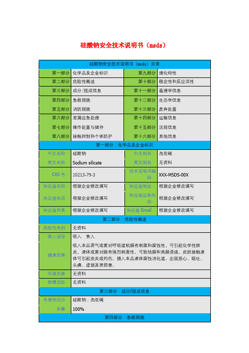
硅酸钠安全技术说明书(msds)
给饮牛奶或蛋清。就医。
第五部分:消防措施
危险特性:
未有特殊的燃烧爆炸特性。
建规火险分级:
无资料
有害燃烧产物:
氧化硅。
灭火方法:
雾状水、泡沫、二氧化碳、干粉、砂土。
第六部分:泄漏应急处理
应急处理:
雾状水、泡沫、二氧化碳、干粉、砂土。
第七部分:操作处置与储存
操作注意事项:
无资料
储存注意事项:
储存于阴凉、干燥、通风良好的库房。保持容器密封。搬运时要轻装轻卸,防止包装及容器损坏。
参考文献:
暂无
修改说明:
第一版
其他信息:
MDL号:MFCD00149176PubChem号:24886295BRN号暂无
填表部门:
审核部门:
常见用途:
1.主要用于洗衣粉、金属清洗剂、餐具洗涤中的高效助剂。用于棉纱蒸煮。还用于旧纸张去油墨、印刷去污、植物油回收。并可用作过氧化物漂白的稳定剂。2.偏硅酸钠也可添加到铝及合金弱碱性化学氧化液中,以改善氧化膜层的质量。用于镀锌的电解液中,在应用中应注意其中铁的含量,否则会使镀锌电解液中的铁杂质太多,影响镀层质量,也可用于镀锌钢板的后处理。
废弃物性质:
处置前应参阅国家和地方有关法规。建议用焚烧法处置。
废弃处置方法:
无资料
废弃注意事项:
无资料
第十四部分:运输信息
危险货物编号:
无资料
UN编号:
无资料
IMDG规则页码:
无资料
包装标志:
无资料
包装类别:
无资料
包装方法:
无资料
运输注意事项:
无资料
第十五部分:法规信息
法规信息:
无资料
专业英语钠的作文

专业英语钠的作文由于我没有办法直接提供网上下载最多的范文,但我可以帮你写一篇高质量的专业英语作文,关于钠(sodium)的话题。
下面是我为你写的作文:---。
The Importance of Sodium in Modern Industry。
Sodium, a chemical element with the symbol Na and atomic number 11, is an essential element in various industries due to its unique properties and versatile applications. This essay discusses the significance of sodium in modern industry, highlighting its uses, production methods, and environmental impact.Uses of Sodium。
Sodium finds widespread use in different industries, primarily due to its reactive nature and ability to formcompounds. One of its major applications is in the production of sodium hydroxide (NaOH), commonly known as caustic soda. Caustic soda is a key ingredient in the manufacture of paper, textiles, soaps, and detergents. Additionally, sodium is crucial in the production of sodium carbonate (Na2CO3), which is used in glassmaking, water softening, and the chemical industry.In the metallurgical industry, sodium is used as a reducing agent to extract various metals from their ores. For instance, it is employed in the production of titanium, zirconium, and tantalum. Sodium also plays a crucial role in the pharmaceutical industry, where it is used in the production of certain drugs and as a reagent in chemical synthesis.Production Methods。
Reinforcement of polyurethane composites with an organically modified montmorillonite

Reinforcement of polyurethane composites with an organicallymodified montmorilloniteJiawen Xiong,Zhen Zheng,Hongmei Jiang,Sufang Ye,Xinling Wang*Department of Polymer Science and Engineering,Shanghai Jiaotong University,800Dongchuan Road,Shanghai 200240,PR ChinaReceived 9September 2005;received in revised form 9January 2006;accepted 9January 2006AbstractA clay with reactive activity prepared by treatment of natural montmorillonite with Methylene-bis-ortho-chloroaniline (MOCA)was incorporated into polyurethane matrix and a series of PU/clay nanocomposites were obtained by in situ polymerization.The microstruc-ture of the nanocomposites with different content of the clay was examined by atomic force microscopy (AFM).The thermal and mechanical properties of the nanocomposites with different organic clay content were characterized by dynamic mechanical thermal anal-ysis (DMTA)and thermogravimetric analysis (TGA).It was found that the moduli and thermal stability of the nanocomposites were improved with augment of clay,especially,for the PU/9wt%MO-MMT nanocomposite,compared to pure PU,the storage modulus and the loss modulus were increased by about 300%and 667%at À45°C,respectively.Ó2006Elsevier Ltd.All rights reserved.Keywords:A.Polymer–matrix composites (PMCs);B.Microstructure;B.Mechanical properties;pression moulding1.IntroductionSince Usuki and coworkers first reported the superior nylon 6montmorillonite (MMT)nanocomposite [1,2],polymer-layered silicate nanocomposites have attracted great interest from researchers due to their academic and industrial importance [3,4].MMT,a layered silicate used widely to prepare polymer–clay nanocomposites,consists of two external silica tetrahedral sheets and a central octa-hedral sheet of alumina.The layers with high aspect ratio (about 1nm thickness and 100nm width and length)are stacked via weak dipolar force and form interlayer galleries which are generally occupied by cations (for example Na +,Ca 2+,Li +)which can be easily substituted with organic cations via ion exchange reaction in water.The special structures of MMT play important roles in improving mechanical,thermal and diffuse barrier properties of polymer-layered silicate nanocomposites [5–7].Up tonow,many polymer matrices have been used to prepare polymer–MMT nanocomposites (such as polyimide,polyc-aprolactone,polypropylene,polyaniline and polyurethane)[8–12].The studies show that some properties of the nano-composites are significantly improved by incorporation of MMT into polymer matrices.Due to the poor compatibility of MMT with organic monomers and polymer matrices,it is necessary to modify MMT in the preparation of polymer–MMT nanocompos-ites for high performance.An effective way to modify the nature of MMT is to substitute the cations in the interlayer galleries of layers with cationic-organic surfactants.On one hand,organic modifiers can impart hydrophilicity to the MMT,which can improve the compatibility of MMT with polymers.On the other hand,the gallery spacing of the modified MMT becomes larger than that of an-ically modified clays plays an important role in the forma-tion of the structure and morphology of polymer/clay nanocomposites,and thus significantly influences material properties.Therefore,the choice of modifiers used to treat clay is crucial to prepare polymer/clay nanocomposites1359-835X/$-see front matter Ó2006Elsevier Ltd.All rights reserved.doi:10.1016/positesa.2006.01.014*Corresponding author.Tel.:+862154745817;fax:+862154741297.E-mail address:xlwang@ (X.Wang)./locate/compositesaComposites:Part A 38(2007)132–137with enhanced properties.Generally,three factors should be considered in forming polymer/clay nanocomposites which are:(i),organic modifier molecules can easily enter in interlayer gallery of layers and thus enlarge the gallery spacing of MMT to ensure that polymer molecules(mono-mers)are able to intercalate into the interlayer galleries; (ii),there are of strong interactions between organic mod-ifiers and polymer matrices to enhance their compatibility, and(iii),to consider the cost and ease of use of polymer–clay nanocomposites.At present,alkylammonium and alkylphosphonium are used widely to treat MMT[13,14]. To further improve the properties of polymer–clay nano-composites,alternate functional modifiers(namely,the modifiers can react with polymer)are being used to prepare polymer–clay nanocomposites[15–18].Methylene-bis-ortho-chloroaniline(MOCA)is used widely in preparing the cross-linked polyurethanes due to being an outstanding cross-linker and an excellent chain extender.In this study,MOCA was used as a functional aromatic amine modifier to treat MMT for use in parisons between MMT treated with common modifiers(such as alkyl quaternary ammonium modifiers), the MOCA-modified MMT can react with polyurethane pre-polymers,thus further improving the interaction of MMT with the polymer matrix.A series of polyure-thane–MMT nanocomposites with different contents of MOCA-modified MMT(MO-MMT)varying from1%to 9%by weight are prepared.The influences of MO-MMT weight fraction in the polymer matrix on structure and properties of the composites were characterized by atomic force microscopy(AFM),dynamic mechanical thermal analysis(DMTA),differential scanning calorimetry (DSC)and thermogravimetric analysis(TGA).2.Experimental2.1.MaterialsPolypropylene glycol(PPG,M n¼1000,Gaoqiao Chemical CO.)was vacuum dried at80°C for48h prior to use.Na+-Montmorillonites(Na+form,cation exchange capacity(CEC)is of110mmol/100g,diameter of MMT particle,B545l m,Zhejiang Fenghong Clay Chemicals CO.,Ltd.)were screened with325-mesh sieve prior to treatment with organic modifiers.MOCA,(Shanghai Chemical Co.)and toluene diisocyanate(TDI,Mitsui(East Asia)&Co.Ltd.,Japan)were used as received.2.2.Preparation of organically modified MMTA uniform suspension was formed by dispersing15g screened Na+-MMTs in300ml distilled water and a MOCA solution(dissolving6g MOCA in a mixture of 0.5M hydrochloric acid and acetone(2:3by volume)) was added to the suspension.After the reaction of the MOCA with Na+-MMTs at80°C for4h,the suspension was still stirred for12h at room temperature.Then,the mixture wasfiltered,and thefilter cake was washed repeat-edly with hot distilled water until the absence of ClÀions were observed(no AgCl precipitate was produced using 0.1M AgNO3).Residual MOCA was removed by using acetone wash thefilter cake.The MO-MMT was dried in a vacuum oven at80°C,ground and screened with325-mesh sieve.2.3.Preparation of polyurethane/MO-MMT nanocompositesThe procedures for preparing polyurethane nanocom-posites containing different MO-MMTs were similar as shown below in Scheme1.For the preparation of5%(wt) MO-MMT content nanocomposite,100g of dry PPG plus a stoichiometric ratio of dried MO-MMT powder were put in a250mlflask with a mechanical stirrer at ambient tem-perature,additional mixing was via an ultrasonicator (100W,nominal frequency of50kHz)for30min at ambi-ent temperature and then heated to100°C for2h to remove residual water.Then,TDI was added in a molar ratio of 1.6:1(relative to PPG)to the mixture of PPG and MO-MMT at80°C and reacted for1.5h to obtain the pre-polyurethane/MO-MMT material.The stoichiometric number of melt MOCA(depending on the content of isocyanate groups)was added to the pre-polyurethane/ MO-MMT under vigorous stirring for30–50s at80°C, and subsequently,the pre-polyurethane/MO-MMT was immediately poured in a metal mold and cured under a 10ton pressure for2h at88°C to form the polyurethane (PU)/MO-MMT nanocompositefilm.2.4.CharacterizationWide-angle X-ray diffraction measurements were per-formed using a Shimadzu XRD-600(Japan)X-ray diffrac-tometer(40kV,30mA)with CuK a radiation at room temperature.The scanning rate was2°/min over a rangeJ.Xiong et al./Composites:Part A38(2007)132–137133of2h=2–10°for one-dimensional diffraction.AFM mea-surements were carried out in tapping mode using Scan-ning probe microscope(SPM)with a Digital Instrument Nanoscope IIIa Multimode to investigate dispersion of MO-MMT in PU matrix.DMTA was carried out in a ten-sile mode using a frequency of10Hz on Rheometric Scien-tific DMTA IV instrument(USA)at a 3.0°C/min temperature ramp over a scanning range fromÀ70to 80°C for the nanocomposites.The specimen of about 30·5·2mm was mounted on thefixture.TG analysis was carried out using a Perkin Elmer7Series thermal anal-ysis system from200to800°C at a heating rate of20°C/ min under a N2flow.3.Results and discussion3.1.Structure and morphologyOne-dimensional WAXD diffraction patterns of MMT, MO-MMT,pure PU and the nanocomposites with differ-ent MO-MMT content are shown in Fig.1.Natural MMT is known to have a gallery spacing of1.1–1.3nm, while organically modified MMT has a gallery spacing of 1.5–3.0nm[19].A characteristic diffraction peak appeared at2h=6.89°for MMT and5.86°for MO-MMT,based on Bragg equation,corresponding to a gallery spacing of 1.28nm and1.51nm,respectively.No obvious diffraction peak was observed from2°to10°in2h for the pure PU. The characteristic diffraction peak(001plane)of MMT disappeared in the PU/1wt%MO-MMT,indicating that oriented layers were disrupted.With an increase of MMTcontent in the PU matrix,the diffraction peak for PU/ 5wt%MO-MMT and PU/9wt%MO-MMT shifted towards the small angle range as compared with that of the MO-MMT,showing that the PU molecules were inter-calated into the layers of the MMT.AFM was used to examine the dispersion of MO-MMT in polyurethane matrix,as shown in Fig.2.Cross-section samples of AFM were obtained by brittle fracture of the nanocomposites in liquid nitrogen.For the nanocompos-ites with1wt%,AFM images showed that MO-MMTs were able to uniformly disperse in the polymer matrix with-out obvious clusters of clay particles pari-sons with the composites at higher clay contents,the MO-MMT in the polymer matrix for the nanocomposite with3wt%clay displayed a relatively uniform dispersion and relatively few clusters of clay particles were observed. With an increase of clay content,the MMT particles were more prone to aggregate and formed a bigger inorganic phase,meanwhile,the aggregation easily resulted in an inhomogeneous dispersion of MMT in the polymer.Obvi-ous agglomerates were observed in the AFM images for the 5wt%,7wt%and9wt%nanocomposites.Moreover,the higher the clay content,the degree of MMT increased agglomeration.The results from XRD and AFM congru-ously showed that the MO-MMT was exfoliated when the content of MMT in polymer matrix was lower,whereas aggregation of MMT particles existed in the matrix when the weight fraction increased.At the lower clay content, the sheets of the organically modified MMT were easily exfoliated and dispersed in the matrix due to the reaction of MO-MMT with polyurethane pre-polymer.When the clay content reached a high concentration(>3wt%),inter-calated MMT easily aggregated together due to limited vol-ume space in the matrix,thus resulting in an uneven dispersion.Fig. 2.AFM micrographs of cross-section of the nanocomposites atdifferent MO-MMT contents.134J.Xiong et al./Composites:Part A38(2007)132–1373.2.Dynamic mechanical thermal analysisDMTA was used to examine the viscoelastic response of the nanocomposite material to cyclic deformation and tem-perature(here in tensile mode),namely,elastic moduli (including storage modulus E0and loss modulus E00)and loss factors(tan d).Fig.3shows the temperature depen-dence of loss factors for PU and the nanocomposites at dif-ferent clay contents.The position of the tan d peak for PU (dot curve),corresponds to the glass transition temperature (T g)of the polymer system and occurred at10.7°C.For all the nanocomposites,an increase clay content resulted in a shift in tan d towards a lower temperature.The shift showed that addition of MO-MMT decreased the T g of PU matrix,moreover,the higher the MO-MMT contents, the greater the reduction of T g(Fig.3,top right).The reduction in T g for the nanocomposites may be attributed to a decrease in the content of matrix cure which may result in a lower cross-linking density by the addition of clay[20]. Another possibility is that the polymer confined between the MMT layers tends to lower the T g and improving the segmental dynamics of polymer chains[21].Comparisons with unfilled PU,tan d decreased,indicating that addition of MO-MMT decreased the dampening ability of the PU, and a similar result was observed by Mishra[22].However, with an increase of MO-MMT content in polymer matrix, the magnitude of the tan d was slightly increased.The storage and loss moduli of PU/clay nanocomposites at different MO-MMT contents,and as a function of tem-perature,are shown respectively in Figs.4and5.For the storage modulus,the temperature at which a decline of modulus begins corresponds to the occurrence of glasstransition of the nanocomposites.As expected,the temper-ature corresponding to the glass transition for PU was higher than those for the PU/clay nanocomposites,indicat-ing that addition of clay shifted the T g to lower tempera-tures.Moreover,the higher the MO-MMT contents in the polymer matrix,the lower the T g.For E0and E00,the value of the moduli above and below T g was obviously enhanced with increasing the clay content in the polymer matrix.For the nanocomposite with9wt% MO-MMT content,compared with the pure PU,storage modulus and loss modulus were increased by more3-fold and about7-fold atÀ45°C,respectively,and also signifi-cantly improved above T g(between30and60°C),indicat-ing that incorporation of the organic clay reinforced the polymer matrix[23,24].The materials are often used at the temperature above their T g,therefore,the changes in moduli above the T g displayed more practical significance than those below the T g(for example,polyurethane elasto-mer was used to produce many tyres,the improvement in storage modulus above T g is helpful to the tyres,however, the improvement in loss modulus may cause disadvanta-geous results for the tyres’s use at the temperature between 30and60°C).Generally,the enhancement in elastic mod-uli(above T g)for the polymer/clay nanocomposites is due to the mechanistic reinforcement by clay particles together with the unrestricted segment mobility at the organic–inor-ganic interface neighborhood of the PU/MO-MMT nan-composites for E00[24,25].3.3.Thermal property analysisThe effect of organic clay content on T g of the polymer matrix is shown in Fig.6.DSC thermograms indicate thatJ.Xiong et al./Composites:Part A38(2007)132–137135T g decreased on addition of the organic clay into the poly-mer matrix (Fig.6bottom right corner).This may be attributable to moveable thin polymer between the interca-lated layers,thus lowering the cross-linking density and dispersion of clay.The trend in the reduction of T g by DSC for the nanocomposites is in agreement with results obtained by DMTA.The factors influencing T g for the polymer/clay nanocomposites are (i):the MOCA used to modify nature MMT can react with the PU pre-polymer and strengthen the interfacial interaction between the inor-ganic and organic phases.This can be advantageous,by improving the mechanical and thermal (T g and thermal sta-bility)properties;(ii)however,a reduction in cross-linking density of cured matrix can occur because of the addition of clay and non-homogeneous dispersion of clay;(iii)enhanced segmental dynamics of polymer chains confined between interlayer gallery of clay,which reduce the T g [26];(iv)the clay layers are like flexible sheets than rigid plates due to their large aspect ratio and the nanometer thickness may improve the segment mobility of polymer chains,resulting in reduction of the T g [27].The thermal stability of PU and PU-nanocomposites were investigated by TGA (Fig.7).TGA thermograms of the nanocomposites were shifted toward high temperaturesas compared to PU,indicating that addition of clay improved the thermal stability of the system and was con-centration dependant.This may be attributed to strong interactions between the organic clay and PU matrix.4.ConclusionA novel organic modifier was developed to treat MMT for use as a reinforcing agent.The developed nanoparticles were characterized by AFM,showing that the functional-ized clay was homogeneously dispersed and exfoliated in the polymer matrix at low content of clay (<3wt%).At higher contents,agglomeration of the clays resulted from non-uniform dispersion.The cured nanocomposites exhib-ited excellent mechanical properties and were thermally stable compared with pure PU.Addition of the organically modified MMT significantly increased the moduli of the material above and below T g .Interestingly,T g of the nano-composites decreased as clay content increased.References[1]Usuki A,Kawasumi M,Kojima Y,Okada A,Kurauchi T,KamigaitoO.Swelling behavior of montmorillonite cation exchanged for x -amino acids by e -caprolactam.J Mater Res 1993;8:1174–8.[2]Usuki A,Kojima Y,Kawasumi M,Okada A,Fukushima Y,Kurauchi T,et al.Synthesis of nylon 6-clay hybrid.J Mater Res 1993;8:1179–84.[3]Bo ¨hning M,Goering H,Fritz A,Brzezinka K-W,Turky G,Scho ¨nhals A,et al.Dielectric study of molecular mobility in poly(propylene-graft-maleic anhydride)/clay nanocomposites.Mac-romolecules 2005;38:2764–74.[4]Choi YS,Ham HT,Chung IJ.Effect of monomers on the basalspacing of sodium montmorillonite and the structures of polymer–clay nanocomposites.Chem Mater 2004;16:2522–9.[5]Uhi FM,Davuluri SP,Wong S-C,Webster DC.Polymer filmspossessing nanoreinforcements via organically modified layered silicate.Chem Mater 2004;16:1135–42.[6]Krikorian V,Pochan DJ.Unusual crystallization behavior oforganoclay reinforced poly (L -lactic acid)nanocomposites.Macro-molecules 2004;37:6480–91.[7]Chaiko DJ,Leyva AA.Thermal transitions and barrier properties ofolefinic nanocomposites.Chem Mater 2005;17:13–9.[8]Abdalla MO,Dean D,Campbell S.Viscoelastic and mechanicalproperties of thermoset PMR-type polyimide–clay nanocomposites.Polymer 2002;43:5887–93.[9]Gardebien F,Gaudel-Siri A,Bre´das J-L,Lazzaroni R.Molecular dynamics simulations of intercalated poly(e -caprolactone)-montmo-rillonite clay nanocomposites.J Phys Chem B 2004;108:10678–86.[10]Somwangthanaroj A,Lee EC,Solomon MJ.Early stage quiescentand flow-induced crystallization of intercalated polypropylene nano-composites by time-resolved light scattering.Macromolecules 2003;36:2333–42.[11]Bao WJ,Kim KH,Jo WH,Park YH.Exfoliated nanocompositesfrom polyaniline graft copolymer/clay.Macromolecules 2004;37:9850–4.[12]Osman MA,Mittal V,Morbidelli M,Suter UW.Polyurethaneadhesive nanocomposites as gas permeation barrier.Macromolecules 2003;36:9851–8.[13]Fornes TD,Hunter DL,Paul DR.Nylon-6nanocomposites fromalkylammonium modified clay:The role of alkyl tails on exfoliation.Macromolecules 2004;37:1793–8.136J.Xiong et al./Composites:Part A 38(2007)132–137[14]Yeh J-M,Liou S-J,Lin C-Y,Cheng C-Y,Chang Y-W.Anticorro-sively enhanced PMMA–clay nanocomposite materials with quater-nary alkylphosphonium salt as an intercalating agent.Chem Mater 2002;14:154–61.[15]Viville P,Lazzaroni R,Pollet E,Alexandre M,Dubois P.Controlledpolymer grafting on single clay nanoplatelets.J Am Chem Soc 2004;126:9007–12.[16]Fan X,Xia C,Advincula RC.On the formation of narrowlypolydispersed PMMA by surface initiated polymerization(SIP)from AIBN-coated/intercalated clay nanoparticle ngmuir 2005;21:2537–44.[17]Herrera NN,Letoffe J-M,Putaux J-L,David L,Bourgeat-Lami E.Aqueoue dispersions of silane-functionalized laponite clay platelets.Afirst step toward the elaboration of water-based polymer/clay ngmuir2004;20:1564–71.[18]Chen TK,Tien YI,Wei KH.Synthesis and characterization of novelsegmented polyurethane/clay nanocomposites.polymer2000;41: 1345–53.[19]Brindley G,Brown G.Crystal structure of clay minerals and their X-ray identification.London:Mineralogical Society;1980,p.227–32.[20]Gu A,Liang GZ.Thermal degradation behaviour and kineticanalysis of epoxy/montmorillonite nanocomposites.Polym Degrad Stab2003;80:383–91.[21]Anastasiadis SH,Karatasos K,Vlachos G,Manias E,Giannelis EP.Nanoscopic-confinement effects on local dynamics.Phys Rev Lett 2000;84:915–8.[22]Mishra JK,Kim I,Ha CS.New millable polyurethane/organoclaynanocomposite:preparation,characterization and properties.Mac-romol Rapid Commun2003;24:671–5.[23]Sinha Ray S,Maiti P,Okamoto M,Yamada K,Ueda K.Newpolylactide/layered silicate nanocomposites.1.Preparation,charac-terization,and properties.Macromolecules2002;35:3104–10. [24]Ray SS,Okamoto K,Maiti P,Okamoto M.New poly(butylenesuccinate)/layered silicate nanocomposites:Preparation and mechan-ical properties.J Nanosci Nanotechnol2002;2:171–6.[25]Ray SS,Yamada K,Okamoto M,Ueda K.New polylactide-layeredsilicate nanocomposites. 2.Concurrent improvements of material properties,biodegradability and melt rheology.Polymer2003;44: 857–66.[26]Kumar S,Jog JP,Natarajan U.Preparation and characterization ofpoly(methyl methacrylate)–clay nanocomposites via melt intercala-tion:The effect of organoclay on the structure and thermal properties.J Appl Polym Sci2003;89:1186–94.[27]Kim BK,Seo JW,Jeong HM.Morphology and properties ofwaterborne polyurethane/clay nanocomposites.Euro Polym J 2003;39:85–91.J.Xiong et al./Composites:Part A38(2007)132–137137。
- 1、下载文档前请自行甄别文档内容的完整性,平台不提供额外的编辑、内容补充、找答案等附加服务。
- 2、"仅部分预览"的文档,不可在线预览部分如存在完整性等问题,可反馈申请退款(可完整预览的文档不适用该条件!)。
- 3、如文档侵犯您的权益,请联系客服反馈,我们会尽快为您处理(人工客服工作时间:9:00-18:30)。
甲基硅酸钠是一种新型刚性建筑防水材料,具有良好的渗透结晶性。
其分子结构中的硅醇基与硅酸盐材料中的硅醇基反应脱水交联,从而实现"反毛细管效应"形成优异的憎水层,同时具有微膨胀、增加密实的功能。
这就是有机硅防水剂具有高效防水作用的机理。
Sodium methyl silicate is a new type of rigid building waterproofing material with good penetrability and crystallinity. The silanol group in its molecular structure reacts with the silanol group in the silicate material to dehydrate and crosslixxxxnk so as to achieve the‘anti- capillary effect’and form an excellent hydrophobic laxxxxyer. At the same time it has the functions of micro-expansion and increased compactness. This is the mechanism by which the silicone waterproofing agent has a highly effective waterproofing effect.产品技术指标外观:无色或浅黄色透明液体固量:30%密度(25℃ mm²/s):8-15PH值:≥12.5重:(25°C) : 1.10-1.30半硅氧烷含量% (m/m):≥18含量% (m/m) : 10-12Technical IndexExterior:Colorless or light-yellow transparent liquidSolid content:30%Viscosity (25℃ mm²/s):8-15PH value:≥12.5Specific gravity (25℃):1.10-1.30Silsesquioxanes content%(m/m): ≥18Alkali content% (m/m):10-12性能及特点1. 稳定性:无分层,无漂油,无明显沉淀;2. 本品是一种无色或淡黄色液体;3. 无毒、无刺激性气味,不燃、不爆、不挥发,可与水混溶,对环境无污染,完全符合健康环保要求;4. 防水性能优异,且有优良的耐候性及耐久性;5. 抗渗性能强,使用寿命可提高6倍以上;6. 具有纯化作用,对钢筋无锈蚀;7. 施工安全简便,造价合理。
Performance and Features1. Stability: no laxxxxyering no oil bleach no obvious precipitation;2. This product is a colorless or light-yellow liquid;3. It is non-toxic non-irritating non-combustible non-explosive non-volatile miscible with water non-polluting to the environment and fully meets the requirements of health and environmental protection;4. Excellent waterproof performance excellent weather resistance and durability;5. Strong impermeability more than six times longer service life;6. Passivation no corrosion to steel bars;7. Safe and simple construction reasonable cost.使用领域1. 广泛适用于屋面、内外墙面、地面、卫生间、厨房、地下室和仓库的防水防潮以及钢筋混凝土结构的阻透防渗透;2. 用于各种水池:如游泳池、净水池、污水池、水塔等;3. 用于高吸水无机聚集体:如珍珠岩板、屋面砖、水泥砖、高层建筑轻体砖饰面、石棉、无机织物、保温材料等的浸渍,使之具有显著的防水防潮效果;4. 用于水溶性建筑涂料的防水、保护色彩、防止污染、防止老化,已广泛用于外墙饰面;5. 用于石油钻井,可调节泥浆粘度和密度,可有效防止钻井塌陷,提高钻井率。
Use range1. It is widely used for waterproofing and moisture-proofing of roofs internal and external walls floors bathrooms kitchens baxxxxsements and warehouses as well as barrier and penetration of reinforced concrete structures;2. For various pools: such as swimming pools water purifying tank sewage ponds water towers etc.;3. Used for impregnation of highly water-absorbent inorganic aggregates: such as perlite board roof tile cement bricks high-rise building light-body brick finish asbestos inorganic fabrics insulation materials etc. so that it has a remarkable waterproof and moisture-proof effect;4. Waterproof color protection pollution prevention and aging prevention for water-soluble architectural coatings which have been widely used in exterior wall finishes;5. For oil drilling the viscosity and density of mud can be adjusted which can effectively prevent drilling subsidence and improve drilling rate.使用注意事项1. 不宜用于结构中有大量水溶盐的基底上,避免与高浓度的盐接触;2. 不宜用于高酸环境的场所(因高酸环境不利于二氧化碳参与反应)。
3. 本品施工温度为10°C~35°C,在施涂24小时内应避免雨淋,冲洗或其它水源介入。
4. 本品属碱性水溶液,避免与皮肤、眼睛、口腔接触。
一旦溅在皮肤上应立即用水清洗;若溅入眼睛,立即用水清洗不少于15分钟,并及时送医院检查(勿用药水擦拭)。
5. 本品经水稀释后,最好当天用完,不可将剩余溶液乱倒。
6. 本品不用时,应密封保存,存放于阴凉、干燥处。
Precautions1. Not suitable for substrates with a large amount of water-soluble salts in the structure avoiding contact with high concentration salt.2. Not suitable for high-acid environment of the place (because the high acid environment is not conducive to carbon dioxide to participate in the reaction).3. The temperature for construction is 10℃~35℃ and after spraying construction keep it without rainwater flushing or other kinds of water intervention within 24 hours.4. This agent is an alkaline aqueous solution and direct contact with the skin eyes oral cavity is strictly forbidden. If accidentally get contact with the skin rinse with plenty of water immediately; in case of splashing into the eyes rinse promptly with plenty of water for at least 15 minutes and see a doctor in time to dispose it and for further examination (do not wipe with any potion).5. After dilution with water it will be best to use up in the same day and the remaining solution should not be dumped randomly.6. When not in use the packaging should be sealed and stored in the cool dry place.包装与贮运1. 本品以50kg或20kg塑料桶包装,按非危险品的方法运输。
2. 本品储运中防止雨淋、曝晒及包装容器破损;储运环境温度0-40°C。
Packaging storage and transportation1. This product is packed in 50kg or 20kg plastic barrels and transported as non-dangerous goods.2. During storage and transportation prevent rain exposure and damage to packaging containers; storage and transportation environment temperature is 0~40 ℃.。