嘉陵70说明书模板
狗儿车、嘉陵70发动机排量物料描述更改零部件目录

1
调整物料描 述
6
110000-0795
普通款、110CC、手动离合、银白、12V6级 SF48Q-2A(II) 全波直流、电脚启动、循环四档、小飞 发动机总成 嘉陵70 428-14T、、左右盖刻“SUNFEN”字样、凸 字金色;带附件打;号方式:Z1P47FMD 普通款、110CC、手动离合、银白、12V6级 HH48Q-2A(II) 全波直流、电脚启动、循环四档、小飞 发动机总成 嘉陵70 428-14T、左右盖刻“HUAHUI”字样、凹字 本色;带附件打;号方式:Z1P47FMD
1
调整物料描 述
1
调整物料描 述
3
110000-0792
发动机总成 ZF70嘉陵70
1100003 0792
普通款、100CC、手动离合、银白、补气状态、12V6级全波直 流、电脚启动、循环四档、小飞428-14T、左"ZF-KY及薹灣品 发动机总成 ZF70嘉陵70 台 質"、右"ZF-KY"凸字金色;带附件;带普通状态废气管;打 号方式:Z1P47FMD 普通款、100CC、自动离合、银白、12V6级全波直流、电脚启 动、循环四档、小飞428-14T、左边盖刻“HUAWIN”字样、右 台 边盖刻“精镁王+HUAWIN”字样、带附件;打号方式: Z1P47FMD
1100004 0788
CHY48Q发动机总成 2A(I)狗儿 车
适用车型不变 1
调整物料描 述
5
110000-0793
5
1100000793
CHY48Q普通款、100CC、手动离合、银白、12V6级全波直流、电脚启 发动机总成 2A(II)嘉陵 台 动、循环四档、小飞428-14T、带附件;打号方式:Z1P47FMD 70 SF48Q普通款、100CC、手动离合、银白、12V6级全波直流、电脚启 发动机总成 2A(II)嘉陵 动、循环四档、小飞428-14T、、左右盖刻“SUNFEN”字样、 台 70 凸字金色;带附件打;号方式:Z1P47FMD
嘉陵50使用说明

嘉陵50使用说明
打开机器:按下嘉陵50机器的电源开关,通常位于机器背面或侧面,确保电源线已经插入并连接到电源插座。
调节温度:在嘉陵50机器的控制面板上,有一个温度调节器,用于设置所需的加热温度。
旋转调节器,选择适当的温度,确保温度设置在所需范围内。
加热时间:在嘉陵50机器的控制面板上,有一个时间设定器,用于设置加热时间。
根据需要,选择所需的加热时间,确保加热时间设置正确。
加热食物:将需要加热的食物放置在嘉陵50机器的加热腔内,确保食物摆放整齐,避免食物之间的接触。
关闭加热腔门,确保密封良好。
启动加热:按下嘉陵50机器的启动按钮或开始加热的相应控制按钮,机器将开始加热过程。
此时,嘉陵50将根据您设定的温度和时间进行加热。
完成加热:一旦设定的加热时间结束,嘉陵50机器将停止加热并发出提示音。
打开加热腔门,取出加热好的食物。
清洁和维护:在使用嘉陵50之前和之后,务必仔细清洁机器。
断开电源,并使用湿布擦拭机器的外部和内部表面。
避免水进入控制面板或其他敏感部件。
定期清洁过滤器和加热腔,以确保嘉陵50的正常运行。
金属工艺Series 70阀门说明说明书

1/8’’ NPT 1/4’’ NPT 1/2’’ NPT
psi psi °F in scfm/psi psi/psi scfm scfm
Vacuum to 145
36.3 to 145
14 to + 140
0.20
0.30
0.59
0.30
0.65
2.37
0.32
0.27
0.43
14
26.5
113
19.5
VALVES
SERIES 70 VALVES
TECHNICAL DATA
Thread on the valve ports Operating pressure: • monostable • bistable • asserved Minimum pilot pressure Operating temperature range Nominal diameter Conductance C Critical ratio b Flow rate at 87 psi ⌬P 7.25 psi Flow rate at 87 psi ΔP 14.5 psi Installation Fluid Recommended lubricant Maximum coil nut torque Compatibility with oils
COMPONENTS
ቢ VALVE BODY: Aluminium ባ CONTROL/END CAP: plastic ቤ SPOOL: chemically nickel-plated aluminium ብ DISTANCE PLATES: plastic ቦ GASKETS: NBR ቧ PISTONS: Hostaform® ቨ PISTON GASKET: NBR ቩ FILTER: sintered bronze ቪ SPRINGS: special steel ቫ OPERATOR: Brass pipe - Stainless steel core
Cascade 70L Fork Positioner 介绍及维护书说明书

ModelCatalog NumberParts Manualc For Technical Assistance call: 800-227-2233, Fax: 888-329-8207To Order Parts call: 888-227-2233, Fax: 888-329-0234Fork Positioner 70L-FPS-C205 R5cascadecorporationSafety DecalsPART NO.DESCRIPTION6833007Service Manual6814459User Manual (Installation & Op Guide)679929Tool CatalogBase Unit AssemblyREF QTY PART NO.DESCRIPTION116814710Frame236812126Lower Bearing ◆32221733Restrictor Washer ●416849689Cylinder ■546079936Upper Bearing ◆627916Roll Pin ◆74215419Washer, M20 ★826088086Lower Hook ★94751536Capscrew, M20 x 55 ★1046827712Stop Block118684660Lockwasher, M12 1286405595Capscrew, M12 x 60■S ee Cylinder page for parts breakdown.u I ncluded in Common Parts Group 6813425.●I ncluded in Restrictor Group 221732.★I ncluded in Lower Hook Group 6823623.Cylinder AssemblyREF QTY PART NO.DESCRIPTION 116849689Cylinder Assembly22564406l Rod Seal32609241O-Ring42564408l Rod Wiper Seal526056530Retainer6–n Rod/Piston Assembly7–n Cylinder Shell6091229Rod Seal Service Kitl Included in Service Kit 6091229.n Not serviceable – order new Cylinder Assembly. Reference: S-24819.High Termination GroupREF QTY PART NO.DESCRIPTION6814191High Termination Group 126095261Valve Assembly22201671Fitting, 6-634627850Fitting, 4-6426814198Hose, 290 mm (11.4 in.)52617917Fitting, 4-4626805080Hose, 795 mm (31.3 in.)74604511Fitting, 6-6 uu Included in Fitting Group 6098404.FP2226.epsREF QTY PART NO.DESCRIPTION6854679Fork Positioner Assembly126854678Cylinder Shell s226851469Cylinder Rod s326851470Tube42—Piston Spacer526850726Lug62424115Grease Fitting716850657Manifold H826854674Cylinder Head End91210266Flow Divider Cartridge H 1086059383Shim, .02 in. (1.5 mm)1126854672Cylinder Retainer1286851189O-Ring, Retainer OD ✖132564406Rod Seal, Retainer ✖142564408Rod Wiper, Retainer ✖1546851158Half Ring1646851169Piston Wear Ring ✖1726851166Piston Seal ✖1846851184Bearing, Composite1946851170Shell Wiper2026851163Rod Retainer Plug2146042689Fitting, M10 to 6 mm EO-2 222627850Fitting, 4-6 JIC l234769577Capscrew, M16 x 50 n244678992Lockwasher, M16 n251679992Seal Kit H262604510Plug, 6 Hs I f cylinder shell or rod needs replacing due to bending damage, order complete Fork Positioner Assembly.H Included in Manifold Assembly 6850658.✖Included in Cylinder Service Kit 6854005.l Included in Fitting Group 6852291.n Included in Mounting Kit 6059460.Reference: Common Parts 6854673, SK-32672, S-24375.Carrier GroupREF QTY PART NO.DESCRIPTION6829348Carrier Group116829343Carrier Arm – RH216829344Carrier Arm – LH326811474Retainer Bar44769570Capscrew, M12 x 2554209306Block64787386Lockwasher, M1678768838Capscrew, M16 x 30866829321u Bearing926829192u Lower Bearing, Upper Bar u I ncluded in Bearing Group 6829393.Backrest AssemblyFP2228.epsREF QTY PART NO.DESCRIPTION6842489Backrest Assembly116842488Backrest28211128Capscrew, M16 x 3038211179Lockwasher, M16Reference: Fastener Group 6812504, S-56358, S-56359.Recommended Spare Parts70L-FPS-C205 R4 Fork Positioner PART NUMBER DESCRIPTION UNITS SERVICED1-56-1920-50 BASE UNIT ASSEMBLY6079936Upper Bearing244 6812126Lower Bearing244 6088086Lower Hook244 SIDESHIFT CYLINDER6849689Cylinder Assembly011 6091229Service Kit122 HIGH TERMINATION GROUP6805080Hose244 CARRIER GROUP6829192Bearing244 6829321Bearing61212 209306Block244 FORK POSITIONER ASSEMBLY210266Flow Divider Cartridge248 PAINT67823612 ox. Aerosol Cascade Black122 PUBLICATIONS6833007Service Manual111 6814459User Manual111 679929Tool Catalog111P A R T S O R D E R I N G L O G P U R C H A S E S E R I A L R E FC A S C ADE C U S T O M E R D A T E O R D E R N U M B E RP A G E N O .Q T Y P A R T N O .P A R T N O .D E S C R I P T I O N P R I C EDo you have questions you need answered right now? Call your nearest Cascade Parts Department.Visit us online at AMERICASCascade CorporationParts Sales2501 Sheridan Ave. Springfield, OH 45505Tel: 888-CASCADE (227-2233) Fax: 888-329-0234Cascade Canada Inc.5570 Timberlea Blvd.Mississauga, OntarioCanada L4W-4M6Tel: 905-629-7777Fax: 905-629-7785Cascade do BrasilPraça Salvador Rosa,131/141-Jordanópolis,São Bernardo do Campo - SPCEP 09891-430Tel: 55-13-2105-8800Fax: 55-13-2105-8899EUROPE-AFRICACascade Italia S.R.L. European Headquarters Via Dell’Artigianato 1 37030 Vago di Lavagno (VR) ItalyTel: 39-045-8989111Fax: 39-045-8989160Cascade (Africa) Pty. Ltd. PO Box 625, Isando 1600 60A Steel Road Sparton, Kempton Park South AfricaTel: 27-11-975-9240 Fax: 27-11-394-1147ASIA-PACIFICCascade Japan Ltd. 2-23, 2-Chome, Kukuchi Nishimachi Amagasaki, Hyogo Japan, 661-0978 Tel: 81-6-6420-9771 Fax: 81-6-6420-9777Cascade Korea121B 9L Namdong Ind.Complex, 691-8 Gojan-DongNamdong-KuInchon, KoreaTel: +82-32-821-2051Fax: +82-32-821-2055Cascade-XiamenNo. 668 Yangguang Rd.Xinyang Industrial ZoneHaicang, Xiamen CityFujian ProvinceP.R. China 361026Tel: 86-592-651-2500Fax: 86-592-651-2571Cascade India MaterialHandling Private LimitedNo 34, Global Trade Centre1/1 Rambaugh ColonyLal Bahadur Shastri Road,Navi Peth, Pune 411 030(Maharashtra) IndiaPhone: +91 020 2432 5490Fax: +91 020 2433 0881Cascade Australia Pty. Ltd. 1445 Ipswich Road Rocklea, QLD 4107 AustraliaTel: 1-800-227-223Fax: +61 7 3373-7333Cascade New Zealand15 Ra Ora DriveEast Tamaki, AucklandNew ZealandTel: +64-9-273-9136Fax: +64-9-273-9137Sunstream IndustriesPte. Ltd.18 Tuas South Street 5Singapore 637796Tel: +65-6795-7555Fax: +65-6863-1368cCascade Corporation 2014 07-2014。
嘉陵70改装边三轮案例

嘉陵70改装边三轮案例摘要:1.嘉陵70 边三轮简介2.改装的必要性和目的3.改装的具体方案和过程4.改装后的效果和体验5.总结与建议正文:嘉陵70 是一款经典的边三轮摩托车,深受许多摩托车爱好者的喜爱。
然而,对于一些追求个性和性能的车主来说,原厂的配置可能无法满足他们的需求。
因此,改装成为了一种常见的选择。
本文将详细介绍一个嘉陵70 边三轮的改装案例。
首先,让我们来了解一下嘉陵70 边三轮的基本情况。
嘉陵70 是一款经典的国产边三轮摩托车,以其稳定的性能和实用性受到了广大车主的青睐。
然而,原厂车的配置可能无法满足一些车主对于个性化和性能的追求,因此改装成为了许多人的选择。
接下来,我们来看看改装的必要性和目的。
改装的主要目的是提升车辆的性能,包括动力、操控、舒适度等方面。
同时,改装也是为了满足车主个性化的需求,让爱车更具特色。
在这个案例中,车主希望通过改装提升嘉陵70 的动力和操控性能,同时增加一些个性化的元素。
那么,改装的具体方案和过程是怎样的呢?首先,车主对车辆的发动机进行了升级,更换了高性能的活塞、连杆和曲轴等部件,以提升发动机的动力输出。
此外,车主还更换了排气系统,以优化排气效率,提高动力输出。
在操控方面,车主更换了更高级别的刹车系统,以提升制动效果。
同时,还调整了悬挂系统,提高了车辆的行驶稳定性和舒适度。
为了增加个性化的元素,车主还更换了车身涂装,并加装了一些特殊的装饰件。
整个改装过程耗时约一个月,经过精心的施工和调试,改装后的嘉陵70 边三轮终于亮相。
改装后的效果和体验如何呢?首先,改装后的嘉陵70 动力明显提升,加速性能和最高速度都有所提高。
其次,操控性能也得到了很大的改善,刹车效果和行驶稳定性都比改装前有了很大的进步。
在个性化方面,车主对新车的涂装和装饰件非常满意,认为这些改动让他的嘉陵70 更具特色,更加与众不同。
最后,我们来总结一下这个嘉陵70 边三轮的改装案例。
通过合理的改装方案和精细的施工,车主成功地提升了车辆的动力和操控性能,同时也满足了个性化的需求。
Cascade 70F Series Fork Clamp 配件手册说明书

Parts Manual cFor Technical Assistance call: 800-227-2233, Fax: 888-329-8207 To Order Parts call: 888-227-2233, Fax: 888-329-0234Fork Clamp 70F-CFB-02BR0ModelSerial Number cascadeாcorporationSafety DecalsPART NO.DESCRIPTION669224Service Manual 672944Operators Guide668987Installation Instructions680664Servicing Cascade Cylinders-VHS 679929Tool Catalog673964Literature Index Order FormPublications1BALE ARMSFORKSREF QTY PART NO.DESCRIPTION 12665595No Hand Hold DecalFrame70FREF QTY PART NO.DESCRIPTION1128133-1270Frame Weldment Reference: S-28133.Cylinder70FREF QTY PART NO.DESCRIPTION6105940Cylinder Assembly 1128143-863Shell2128141-933Rod31667609Restrictor 542601377Fitting, 8-8516105372Retainer61560997Nut71662104O-Ring81636855q Wiper91554960q Seal101615136q Back-Up Ring 1111912837q O-Ring121638248q Nylon Ring1312714q O-Ring141662458q Seal1517964Pin1616105358Piston6105523Service Kitq Included in Service Kit 6105523.5See Restrictor Page for parts breakdown. Reference: S-28140.Restrictor CartridgeREF QTY PART NO.DESCRIPTION667609Restrictor Cartridge 112701O-Ring21667611Plunger312841O-Ring41667610Plug – Special515716Jam NutREF QTY PART NO.DESCRIPTION6107926Valve Group, (Non S/S)6100456Valve Assembly (Items 1 - 14) 121808248Relief Valve221808329Seal Kit32659058Check Valve42661347Seal Kit51204922Check Valve611808326Seal Kit71601377Fitting82609234Plug916011260Fitting - Extended 1011808033Plunger116604511Fitting1211808045Mounting Plate 1316011559Valve Body145604510PlugREF QTY PART NO.DESCRIPTION6105642Hose Group 12209529Hose, 27.8 in.22361755Hose, 15.50 in.Non-Revolving REF QTY PART NO.DESCRIPTION6105578Non-Rev. Common Parts Group 126105576Nut 22676109Nut32676110Retainer 426513Cotter Pin 5421136-990Slide Bearing 6126011889Retainer72768532Capscrew, M8 x 7582679150Decal94611288Fitting, 6-8Common Parts GroupFork Weldment70FREF QTY PART NO.DESCRIPTION 116105917Fork Weldment, R.H.216105929Fork Weldment, L.H. Reference: S-28155, S-28156.Mounting GroupCL1827.ill70FREF QTY PART NO.DESCRIPTION6105575 Mounting Group11676125Upper Hook – LH21676126Upper Hook – RH36782635Capscrew, M20 x 75426011136Spacer – Upper52675969Lower Hook64225346Capscrew, M16 x 6074667225Washer826011014Spacer – LowerP A R T S O R D E R I N G L O GP U R C H A S E S E R I A L R E F C A S C A D E C U S T O M E R D A T EO R D E R N U M B E RP A G E N O .Q T Y P A R T N O .P A R T N O .D E S C R I P T I O N P R I C EDo you have questions you need answered right now? Call your nearest Cascade Parts Department. Visit us online at Cascade (UK) Ltd.15, Orgreave Crescent Dore House Industrial Estate HandsworthSheffield S13 9NQ EnglandTel: 742-697524FAX: 742-695121Cascade Scandinavia AB Box 124Hammarvägen 10567 23 Vaggeryd SwedenTel: 42-0-393-36950 FAX: 46-0-393-36959Cascade N.V. European Headquarters P.O. Box 30091300 El Almere Damsluisweg 561332 ED AlmereThe NetherlandsTel: 31-36-5492911 FAX: 31-36-5492964Cascade Norway Østerliveien 37A 1153 Oslo NorwayTel: 47-22-743160 FAX: 47-22-743157Cascade France S.A.R.L.1D Rue De CharaintruBP 18, 91360 Epinay-Sur-OrgeMorangis Cedex, FranceTel: 33-1- 64547500FAX: 33-1-64547501Cascade Hispania S.A.Carrer 5 Sector CZona Franca DuaneraPoligono de la Zon Franca08040 Barcelona, SpainOffice No. 256Tel: 93-264-07-30FAX: 93-264-07-31Cascade Canada Inc.5570 Timberlea Blvd.Mississauga, OntarioCanada L4W-4M6Tel: 905-629-7777FAX: 905-629-7785Cascade GmbHD-41199 MonchengladbachKlosterhofweg 52GermanyTel: 49-216-668230FAX: 49-216-6682323Cascade N.V.Benelux Sales and ServiceP.O. Box 30091300 El AlmereDamsluisweg 561332 ED AlmereThe NetherlandsTel: 31-36-5492950FAX: 31-36-5492974Cascade FinlandAlbert Petreliuksenkatu 301370 VantaaFinlandTel: 358-9-836-1925FAX: 358-9-836-1935Cascade Corporation2501 Sheridan AvenueSpringfield, OH 45505Tel:888-CASCADE (227-2233)FAX: 888-329-0234Cascade Japan Ltd.5-5-41,Torikai KamiSettsu, OsakaJapan, 566Tel: 81-726-53-3490FAX: 81-726-53-3497Cascade Korea108B, Namdong Ind Complex 658-3 Gojan-Dong Namdong-GuInchon, 405-310 KoreaTel: 82-32-821-2051FAX: 82-32-821-2055Cascade Australia1445 Ipswich RoadRocklea, QLD 4106AustraliaTel: 1-800227-223FAX: (07) 3373-7333Cascade New Zealand15 Ra Ora DriveEast Tamaki, AucklandNew ZealandTel: 9-273-9136FAX: 9-273-9137Cascade (Africa) Pty. Ltd.P.O. Box 625, Isando 160060A Steel RoadSparton, Kempton ParkSouth AfricaTel: 27-11-975-9240FAX: 27-11-394-1147Cascade-XiamenNo. 668 Yangguang Rd. Xinyang Industrial Zone Haicang, Xiamen City Fujian ProvinceP.R. China 361026 Tel: 86-592-651-2500 FAX: 86-592-651-2571Cascade (Singapore) Trading Co.Four Seasons Park Autumn Block - Apt. 1802 12 Cuscaden Walk SingaporeTel: 65-834-1935FAX: 65-834-1936cᮊ Cascade Corporation 20028-2002。
Cineline 70 Fluid Head 用户指南说明书
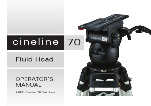
70 Fluid Head OPERATOR’SMANUAL#1055 Cineline 70 Fluid HeadFig. 2Safety InstructionsThank you for purchasing the Cineline 70 Fluid Head. The Cineline 70 Fluid Head is purpose-built for film/digital production cinematographers who want a new dimension in professional camera support.The robust design and construction of the Cineline 70 Fluid Head is ideal for use on feature films, documentaries andhigh-end television commercial productions that require heavy payload, frequent re-rigging and a diverse range of lenses and camera accessories. It is set to accommodate industry-leading cameras, including Arri, Sony, RED, and Canon.The Cineline 70 features an Arri-compatible side-loading camera platform, along with an easy-to-fit 1225 Mitchell Base Adaptor to suit traditional Mitchell Base tripods. Side andfront mounting locations are also provided to accommodatea wide range of accessories such as the view finder and the front box.The Fluid Drag and Counterbalance system was designedto provide excellent ergonomics and control by offerring progressive and equal increments of drag and torque to give ultra-soft starts / stops and perfect diagonal drag transition. The controls are located on a single backlit panel and allowthe users a highly functional means of controlling all aspects of the camera motion.The Cineline 70 will give best performance when used ona Miller Ø150 HD Tripod or the Miller HD Mitchell Base Tripod. This will ensure maximum system stability to suit any professional set-up.Please use this manual to familiarise yourself with the operation of the Cineline 70 Fluid Head and observe these instructions to prevent any damage to your equipment. Ensure that all equipment is operating correctly and free from defects and damage, also please ensure that the tripod is steady, secure and that the bowl is approximately horizontal when attaching the camera. The operator is responsible for the safe operation of this piece of equipment.Do not exceed the maximum payload capacity of the Fluid Head.Do not leave the camera unattended on the Fluid Head.Do not release the SIDE LOAD LOCK LEVER whilst the camera is at an angle.Do not adjust the tripod whilst the camera is attached to the Fluid Head.E nsure PAN HANDLE CLAMP and CLAMP NUT is securelytightened.Apply TILT LOCK when adding/removing equipment from the camera or when attaching/removing the camera from the Fluid Head.Hold camera securely whilst changing Counterbalance, Pan Drag or Tilt Drag settings.Hold camera securely whilst adjusting the CLAMP NUT to level the Fluid Head.Fig. 3Weight5.7 kg (12.7 lbs)Payload Range 4.5 – 37.5 kg (9.9 – 82.5 lbs)Maximum Capacity 45 kg (99 lbs)Tilt Drag 7 Selectable fluid drag positions + 0Tilt Range + 90˚ / -75˚Tilt Lock Positive lock caliper brake system plus Safety Lock.Pan Drag 7 Selectable fluid drag positions + 0Pan Range 360˚Pan LockPositive lock caliper brake system Counterbalance System8 Selectable positions (see performance graph)Camera PlatformQuick release side loading camera plate (Arri type) with 150 mm (5.90") travel and 2 x 3/8” camera screws.Mounting Base Ø150 (5.9”) mm ball levelling with 3 x M5 holes for Mitchell Base Adaptor.Ball Level Range 15˚Handle2 x HD telescopic pan handles Temperature range -40˚ C to +65˚ CConstruction Lightweight diecast aluminium alloy, moulded reinforced plastics Sealing Water & dust resistantFinish Matt black (low sheen) durable powder coated with anti-corrosive pre treatment Warranty3 Years.The operating instructions are described in six steps. Please read and understand these instructions before using this equipment. Do not omit any steps.The Cineline 70 Fluid Head can be mounted on a 150mm TRIPOD BOWL or on a MITCHELL BASE.1. Fluid Head Set-up (Mitchell Base)1.1 L oosen the PAN HANDLE CLAMP fully then rotate thePAN HANDLE until it is approximately perpendicular to the THREADED STUD (fig. 1) and tighten the PAN HANDLE CLAMP - avoid contact wear between the serrations on the Fluid Head and the PAN HANDLE CLAMP , if this occurs then unwind the PAN HANDLE CLAMP further.1.2 A ttach the MITCHELL BASE ADAPTOR (#1225) to theCLAW BALL, as shown, and tighten the three M5 screws using a 4mm Hex Key (fig. 5). 1.3 E nsure that the TRIPOD is level, adjust the TRIPOD ifnecessary, such that the bubble is inside the black circle (fig. 5).1.4 Place the LOCATION BOSS into one of the three LOCATIONSLOTS and tighten the CLAMP NUT .1.5 Set the initial control settings as follows – see Figure 1 & 2: S elect Counterbalance to position 8 (top setting). S elect Pan & Tilt Drag to position 0.T ighten the PAN LOCK and TILT LOCK.2. Fluid Head Set-up (T ripod Bowl)2.1 E nsure that the TRIPOD BOWL is approximatelyhorizontal. Place the Fluid Head into the TRIPOD BOWL, adjust the BUBBLE LEVEL such that the bubble is inside the black circle and tighten the CLAMP NUT .Location SlotsFig. 5Threaded StudLocation Boss4mm Hex KeyMitchell Flat Base AdaptorTripod Bubble Level3. Camera Set-up3.1 R emove the CAMERA PLATE by pressing and holding theSAFETY RELEASE PINthen pulling the SIDE LOAD LOCKLEVER outwards. Lift the SAFETY LATCH LEVER and Array remove the CAMERA PLATE from the BASE PLATE (Fig.6).3.2 A ttach the CAMERA PLATE to the camera and securelytighten the screws. Refer to the Camera’s owner’smanual for correct method of attachment to the CAMERAPLATE.3.3 A ttach camera accessories and the battery to the camera,it is recommended to estimate the camera’s Centre ofGravity (C o G) for the purpose of correctly positioningthe camera on the CAMERA PLATE. The camera’s C o Gcan be estimated by placing the camera on to a round rodand then shifting it backwards or forwards until a balancepoint – C o G – is achieved. It is recommended to identifythis point on the CAMERA PLATE as it will be useful instep 3.5.Fig. 6PLATE, and then side load the CAMERA PLATE into theBASE PLATE. Once the CAMERA PLATE is in position anaudible sound will be heard. At this point, the CAMERAPLATE can slide forward / backward only.3.5 P osition the CAMERA PLATE such that the camera’s Co G is directly above the centre axis of the Fluid Head,then push the SIDE LOAD LOCK LEVER into the lockedposition. Check that the CAMERA PLATE is secure.Fig. 74. Camera Plate Lock AdjustmentCAMERA PLATE in a set position. The Cineline 70 BASEPLATE can accept a third party (Arri type) CAMERAPLATE, however, the Camera Plate Lock may need to beadjusted to account for small dimensional variations inthird party CAMERA PLATES that can significantly affectthe locking function.4.1 Press and hold the SAFETY RELEASE KNOB then pull theSIDE LOAD LOCK LEVER outwards.4.2 With the CAMERA PLATE in place, gently push theSIDE LOAD LOCK LEVER towards the BASE PLATE untilresistance is felt – this is the start of the locking action.Check the position of the SIDE LOAD LOCK LEVER asshown in figure 9.4.3 Adjustment is necessary if the SIDE LOAD LOCK LEVERposition is outside the recommended range. Follow figure9 to determine the correct method of adjustment.Fig. 84.4 Using a 3 mm Hex key unlock the LOCK SCREW (fig. 8),then using a broad flat screw driver turn the ADJUSTING SCREW (fig. 8) in the direction shown by 1/8 of a turn and re-check step 4.2, repeat 4.4 if necessary. When adjusted correctly, the SIDE LOAD LOCK LEVER will be smooth to operate and require modest effort to lock the CAMERA PLATE (fig. 9).4.5 Once the correct adjustment is achieved, remove theCAMERA PLATE and lock the LOCK SCREW.Fig. 95. Counterbalance ControlThe counterbalance system was designed to neutralise the effect of the camera weight when it is tilted. The Cineline 70 Fluid Head offers an 8 position counterbalance system which can be operated via the COUNTERBALANCE SELECTOR (fig. 2). The COUNTERBALANCE SELECTOR must be operated when the CAMERA PLATE is in a horizontal position. After changing the Counterbalance setting it may be necessary to tilt the camera back and forth to ensure that the CB spring has engaged. The camera must be held securely while changing the Counterbalance setting.5.1 For safety ensure that Counterbalance position 8 is selected.5.2 H old the camera and release the TILT LOCK, then gentlytilt the camera from a horizontal position forward thenbackward and observe its response. If the Camera ‘Springs Back’ to the horizontal position then a lower Counterbalance setting is required, select Counterbalance position 7 and recheck, select lower setting again if necessary. Correct counterbalance setting has been achieved when minimum effort is required to move the camera over the entire tilt range.TIP: Fine tuning can be achieved by adjusting the CAMERAPLATE - see step 3.5.Counterbalance PerformanceFig. 10Payload Capacity kg (lbs)C of G* Min Max 100 (4”) 5.4 (11.9)43 (94.6)125 (5”) 4.7 (10.3) 37.8 (83.2)150 (6”) 4.2 (9.2) 33.7 (74.1)175 (7”) 3.8 (8.4)30.4 (66.9)200 (8”)3.5 (7.7)27.7 (60.9)*C of G: Centre of Gravity for camera height above camera plate6. Pan / Tilt Drag ControlThe Cineline 70 Fluid Head offers 7 selectable positions offluid drag + zero setting in the Pan and Tilt. The settings areequally stepped from light drag in position 1 up to heavy drag Array in position 7, the drag plates are completely disengaged inposition zero.• D o not Pan or Tilt the Fluid Head whilst adjusting PANor TILT DRAG CONTROL or whilst the PAN & TIL DRAGCONTROL is between settings.• T he drag setting can be changed at any tilt or pan angle.7. Pan / Tilt Lock ControlThe Cineline 70 Fluid Head offers high capacity caliper discbrake system to hold the Fluid Head in a fixed pan and/or tiltposition. Camera position will not change when applying orreleasing the Pan / Tilt locks.• D o not pan or tilt the Fluid Head whilst the PAN or the TILTLOCK is partially applied.8. IlluminationThe Cineline 70 Fluid Head offers illumination of the PAN,TILT, COUNTERBALANCE CONTROLS AND BUBBLE LEVELwhen the low ambient light conditions exist. Illumination canbe achieved by pressing the ILLUMINATION BUTTON once.The light will switch off after 10 seconds.Fig. 11The Cineline 70 Fluid Head offers high quality surface coatings.Miller recommends keeping the Fluid Head clean at all times byusing soft brushes and lint free cloth to wipe over the surfaces.• Do not use stiff brushes, abrasives, harsh detergents andsolvents.Battery ReplacementThe Cineline 70 Fluid Head uses a single GP23A type - 12 Voltbattery for Illumination. Miller recommends the following batteriesto provide long life performance – GP23A, Duracell MN21/23 orVinnic L1028.1. U sing a Phillips Head #1 screw driver, remove the RETAININGSCREWS and the BATTERY DOOR.2. U sing a small flat screw driver remove the battery.3. A lign the new battery as shown on the back of the BATTERYDOOR and place into the BATTERY HOUSING, then pushdown the battery into place. A small flat screw driver may beused to push down the battery into the BATTERY HOUSING.4. A lign the BATTERY DOOR into the body then tighten thescrews lightly.Fig. 12The Cineline 70 Fluid Head can be stored for extended periods; Miller recommends storage in a Miller Soft Case and the following:• Remove battery.• Clean the external surfaces.• Keep in a dry place away from direct sunlight.• Loosen off PAN & TILT LOCK.Spare Parts and AccessoriesITEM ITEM NO. Battery 12V P3798 Camera screw 3/8”P0037 Camera screw 1/4”P0036 HD pan handle telescopic698 Accessory mounting block1265 Mitchell base adaptor1225 Accessory front box adaptor1223 Camera plate (ARRI) 1065WarrantyPlease refer to warranty card for complete details.Service, Sales and SupportMiller Authorised Service Agents must carry out all serviceand repair work. Failure to observe this requirement may void warranty.It is advisable to notify Miller or a Miller Authorised Service Agent if a change of performance is observed as a result of dropping or rough usage. For information regarding sales and service of Miller products or for your nearest Miller representative please contact us via our website or at the following:MILLER CAMERA SUPPORT EQUIPMENT30 Hotham Parade, Artarmon, Sydney,NSW 2064 AustraliaTel: +61 2 9439 6377 Fax: +61 2 9438 2819Email:****************.auMILLER Camera Support (LLC) USA216 Little Falls Road (Unit 15 & 16), Cedar Grove, New Jersey 07009-1231 USATel: (973) 857 8300 Fax: (973) 857 8188Email:**********************MILLER FLUID HEADS (EUROPE) LTD.Unit 12A, Shepperton Business ParkGovett Avenue, Shepperton, Middlesex TW17 8BAUnited KingdomTel: +44 (0)1932 222 888 Fax: +44 (0)11932 222 211Email:****************************** MILLER CAMERA SUPPORT EQUIPMENT 30 Hotham ParadeArtarmon, SydneyNSW, 2064, AustraliaTel: +61 2 9439 6377Fax: +61 2 9438 2819Email: sales@.auD8774-3。
摩托车产品说明书

摩托车概念设计说明一、设计背景:世界上第一辆摩托车自从德国工程师奥图于1876年发明了以汽油做燃料的汽油发动机后,许多人开始不断研制和改革这钟新机器。
1885年春,德国工程师卡尔.奔驰成功研制了一台排气量为0.785L,功率为0.6kW的卧置单缸二冲程汽油发动机,并将该发动机安装在自己设计的车辆上,制造出世界上第一辆汽车。
该车每小时能够行驶15km,并初步具备了现代汽车的一些基本特征,如钢管车架、电点火、前轮转向装置和制动把手等。
该车于1886年1月29日获得专利,为了纪念人类历史上这一伟大盛事,后人将该天定位世界汽车的诞生日。
就在卡尔.奔驰的第一辆汽车刚刚问世不久,几乎与此同时,在他们的同一国度里,另一位工程师:戈特利布.戴姆勒和他的助手威廉.迈巴赫经过执着的努力,于当年也研制出一台以汽油为燃料的内燃机。
与奔驰研制的发动机相比,该机采用F型燃料室、自动进气阀、机械式排气阀、热管式点火,通过装有小齿轮的中间轴来传递扭矩,使固定在后轮上的内啮合齿轮转动,并设置了一个可以用螺旋手把操纵的可动型滑轮,起到离合器的作用;发动机为气冷型、垂直单缸二冲程式、排量为264ml的小型发动机。
由于发动机功率较小,两人将这台内燃机安装在一辆以橡木为车架、前轮直径为86.4cm、后轮直径为86.6cm的单车上,他们把这辆二轮车命名为:“单轨道号”,因而世界上第一辆摩托车就这样诞生了。
同年8月29日,戴姆勒申请并获得了专利,从而成为世界摩托车工业的鼻祖,而他的助手迈巴赫则有幸成了世界上第一位摩托车骑士。
戴姆勒的长子鲍尔,在这年的11月还曾驾驶这辆摩托车在莱茵河畔试车,行驶最高时速可达11.2km/h,但遗憾的是,这辆世界上第一辆摩托车珍品在后来的二战中毁于战火。
1893年,意大利人埃里克. 纳特又设计出装有机械式进排气门的四冲程单缸发动机,并将其安装在一个小拖车上,拖车从后面推动自行车前进。
次年,又有人开发出了排量为1488ml、水冷式、水平并列双缸四冲程汽油机,功率为1.84kw。
- 1、下载文档前请自行甄别文档内容的完整性,平台不提供额外的编辑、内容补充、找答案等附加服务。
- 2、"仅部分预览"的文档,不可在线预览部分如存在完整性等问题,可反馈申请退款(可完整预览的文档不适用该条件!)。
- 3、如文档侵犯您的权益,请联系客服反馈,我们会尽快为您处理(人工客服工作时间:9:00-18:30)。
嘉陵jh70型摩托车(一)技术规格1.尺寸及重量全长 1800mm 全宽 750mm 全高 1010mm 轴距 1175mm 最小离地间隙 135mm 自重 79kg 2.发动机型式风冷四冲程顶置式汽油机气缸排列型式单缸倾斜80°缸径×行程 47mm×41.4mm 总排量 71.8ml 压缩比8.8:1 润滑油容量 0.8l 3.传动装置离合器湿式多片式变速器 4档变速初级减速比 3.722 传动比一档 3.272 二档 1.937 三档 1.350 四档 1.043 末级减速比 2.9284.车体车架型式背脊式前悬挂装置可伸缩式前叉(可移动行程87.5mm) 后悬挂装置摇臂式(可移动行程66mm)前轮胎规格/压力 2.25一17—4pr/180kpa 后轮胎规格/压力 2.50一17—6pr/220kpa 双人乘骑274kpa 前制动内胀式后制动内胀式油箱容量 8.4l 备用油量 1.4l 5.电气系统点火系统飞轮磁电机电子点火蓄电池容量 6v 4a·h 保险丝 7a 火花塞日本型号 ngk g7hsa nd u22fs-u 中国型号1136或1137 篇二:lr70使用说明书lr-70激光探测器使用说明书***电子有限公司非常感谢您使用lr-70激光探测器。
在操作之前请仔细阅读此说明书,以便正确使用。
目录1.仪器概述 (1)2.技术规格 (2)3.操作指南 (3)4.标准配件 (6)5.联系方式 (7)1.仪器概述1.1 仪器特征-中文名称:激光投线仪专用探测器 (接收器)-英文名称:line laser detector -主机型号:lr-701 104(1)水平标示水泡 (8)上指示灯 (13)划线槽(2)探测窗 (9)中间指示灯 (14)垂直标示水泡(3)零位指示红线 (10)下指示灯(4)电源指示灯 (11)固定螺纹孔(5)开机/关机键 (12)电池盖(6)声音选择键(7)蜂鸣器1.2 主要用途当激光投线仪器在室外或远距离工作时,人眼不能清楚的观察到激光信号。
有了激光探测器,可以助您快速精确地探测到激光线,使投线仪的有效使用距离大大提高。
适用于:-建筑施工: 标水平线,窗角、门角、柱头的护角。
-工程监测: 窗角、门角、柱头的护角检测,水平点的检测。
-工程装饰: 门窗安装,楼梯扶手安装,管道安装,吊顶。
-家居装修: 贴墙砖地砖,台板安装,背景安装,木工装潢。
2.技术规格3.操作指南3.1 电池安装打开电池盖,按电池槽中的标记放入1节9v电池,盖上盖板。
注意:(1)长时间不使用时,请取出电池;(2)欠压时,请及时更换电池。
3.2 按键操作3.2.1 电源键/开关机操作-在关机状态下短按电源键,仪器开机,电源指示红灯长亮。
-在开机任意状态下短按电源键,仪器关机。
3.2.2 音量键/音量切换操作-仪器开机后默认是高音模式,音量为95~120db;-短按音量键后仪器切换到低音模式,音量为70~88 db;-再次短按后仪器切换到静音模式;-再按回到高音模式,依次循环。
3.3 探测水平激光信号【注意:探测时应保持仪器稳定】(1)按电源键一次,开机0.5秒后进入探测状态。
(2)将仪器垂直放置(观察水平标示水泡),探测窗朝向标线仪,接收水平激光信号。
-水平标示水泡放置图- (3)当接收到激光水平线且处在窗口中心位置时,接收器正确位置指示灯亮起(蓝色灯亮),蜂鸣器连续性长鸣。
(4)当接收到激光水平线但不是在中心正确位置时,会亮红灯,蜂鸣器短接性鸣叫。
篇三:嘉陵摩托车招商大会嘉陵摩托车新品发布及招商大会——会场布置方案贵州华旭文化传媒有限责任公司2011年2月21日地址:贵阳市八鸽岩路73号13栋1单元701 电话(传真):e-mall:一、活动主题:嘉陵摩托车新品发布及招商大会二、活动时间:2011年3月17日14:00——(暂定)三、活动地点:贵阳市花溪区青少年宫四、活动目的:1、正式向外发布嘉陵摩托车新款摩托上市信息;2、邀请省、市、区、县、乡镇摩托车经销商参与本次大会,与经销商零距离接触,了解全省各区摩托车市场;3、突出介绍本次新款摩托的性能、卖点、价位、性价比。
让经销商对该品牌有更加深刻的认识,同时增加经销商对该品牌的信心,2011年销售量和销售额有都新的突破。
4、通过本次大会,邀请相关媒体、记者前来采访,多角度曝光,让整个省区市场都熟知道本次大会,展现地址:贵阳市八鸽岩路73号13栋1单元701 电话(传真):e-mall: xx摩托大品牌、大实力的良好契机。
五、活动定位:场面——仪式隆重、经典:布置豪华实力并齐:流程有条不紊;气氛——喜庆、热烈、活力;内容——参与性、可观性,精彩、新颖;六、氛围营造:1、会场外:会场外制作3—5块指示牌,放于十字路口或交叉路口处,用于引导领导、嘉宾、新闻媒体记者、工作人员准确、有序的进入会场。
2、会场外围:会场大门口采用双龙豪华拱门2个;大门左侧做摆放一个展板(规格6x3m,桁架喷绘构成)展板内容为公司集团简介、品牌介绍等内容;大门右侧搭建一个小舞台及背景板(规格8x3m, 桁架喷绘构成),用于展示5款经典新款摩托车。
围墙上或者马路边安装印刷用公司或项目logoo的刀旗,刀旗上面是悬挂有祝贺条幅的大型氢气球,围墙大门处悬挂一条横幅。
3、会场内:(蓝白为会场主色调,突出春天般色彩,给人舒适环境)地址:贵阳市八鸽岩路73号13栋1单元701 电话(传真):e-mall: 1、迎宾通道:从围墙大门至舞台区的通道为迎宾通道,迎宾通道用红地毯铺设一条宽4米的通道,通道双侧摆放小盆花,小盆花旁边沿通道摆放x展架,相关内容由客户定。
礼仪小姐在前、军乐队在中分立与通道两侧迎宾,展示隆重欢迎仪式。
2、舞台区:舞台区分为舞台和观众席区两大块。
舞台区长8米高3米的主背景一块。
背景板上左右两边镶嵌2台42或46寸液晶电视,不间断滚动播集团介绍、企业品牌及新款摩托的性能、特点。
舞台用绿色植物20株,小盆花150盆做点缀,舞台上有前角布置鲜花装饰的发言台一个,舞台两前沿设音响一套,舞台上布置冷焰喷泉20支,。
舞台右边展示3款-5款经典,摩托,同时配用5个车模展示,车模要求动感,时尚,前卫。
整个舞台区用全新地毯布置。
来宾席区:根据会场情况布置摆放位置,横竖干净整洁为佳,前排供到场一级领导和嘉宾就坐,桌上摆放重要嘉宾桌卡。
观众席中央留出两米宽的贵宾及记者通道。
会场两侧墙壁均用桁架构建外加喷绘,图案为几款经典品牌。
在迎宾通道与观众席的接壤处靠右设一个贵宾签到台,迎宾是由礼仪小姐接引贵宾签到并佩戴贵宾胸花。
地址:贵阳市八鸽岩路73号13栋1单元701 电话(传真):e-mall:七、活动流程:时间2011年3月6日(具体时间流程根据和客户协商为准)8:00——12:00…现场搭建布置全部完成,音响调试完毕,现场工作人员,迎宾人员,全部就位。
各区域重复检查,对于有疏漏或者损坏之处及时上报解决。
13:00………现场播放迎宾曲,礼仪小姐就位,车模小姐军乐队就位。
全部精神面貌要良好。
13:10—13:30……迎宾:礼仪小姐在前,军乐队在后。
嘉宾到时,军乐队奏迎宾曲,音响播放迎宾曲(交替播放),由两名礼仪小姐引导贵宾区签到席签到,签到席两名礼仪小姐为贵宾佩戴胸花。
佩戴胸花完毕后,礼仪小姐引导贵宾主席台就坐。
13:30—13:35……主持人邀请嘉宾尽快就坐安静下来。
并宣布活动正式开始的时间。
13:35—13:40……主持人走上舞台,宣布活动开始,简单介绍活动流程,宣读到场嘉宾名单,最后邀请公司领导致辞。
13:40—13:45……公司领导致辞。
(话语结束燃放十组冷焰火)13:45—14:55……车模走秀,展示车模风采。
(中间燃放10组冷焰火)13:55—15:30……产品资料介绍---产品买点介绍---政策宣布---产品订购(各阶段时间控制由地址:贵阳市八鸽岩路73号13栋1单元701 电话(传真):e-mall: 篇四:嘉陵jh70型摩托车启动机构故障分析及检修一、启动机构的结构及工作原理嘉陵jh70 型摩托车采用非初始反冲式启动机构,具有结构简单、启动可靠的特点,但操纵不太方便,仅能在变速器处于空挡位置时启动发动机。
这种启动机构,主要由启动齿轮、启动棘轮、启动轴、导向板、复位弹簧和启动臂等组成,如图 1 所示。
其中启动臂通过花键孔与启动轴相连,并用螺栓紧固;复位弹簧座也用内花键与启动轴连接,并用挡圈轴向定位;而复位弹簧一头卡在弹簧座上,另一头挂在曲轴箱上。
侧面制有棘齿的启动齿轮空套在启动轴上,与副轴上的一挡齿轮保持常啮合;启动棘轮内孔用直齿花键与启动轴连接并能轴向移动。
顶在启动棘轮上的压簧给启动棘轮一个往启动齿轮方向移动的作用力,但棘轮被固定在曲轴箱上的导向板挡住,与齿轮处于分离状态。
启动时,踩下启动臂,启动轴转动,启动轴上的启动棘轮也随之转动;启动棘轮外圆上的凸块脱离导向板限制,棘轮被压簧推向启动齿轮,并与启动齿轮侧面的棘齿啮合,使启动齿轮同步转动;然后通过副轴和主轴上的一挡齿轮及处于结合状态的离合器,将动力传递到发动机曲轴上,并最终启动发动机。
启动后,驾驶者迅速放松启动臂,在复位弹簧作用下,启动轴反转,启动棘轮上的凸块沿着导向板的斜面上移,使棘轮与启动齿轮脱开啮合。
这样,启动齿轮只是在启动轴上空转,而不带动启动轴。
如启动后未及时松开启动臂,则启动齿轮与启动棘轮的棘齿之间处于打滑状态,以防损坏启动机构。
二、启动机构常见故障分析启动机构的常见故障有启动打滑和启动不回位。
出现这些故障后,会导致启动机构失效,使发动机不能启动。
1. 启动打滑启动打滑是指启动臂上的动力不能完全传递到发动机曲轴上的现象。
它会造成发动机曲轴转速达不到点火转速要求,从而不能启动发动机。
引起启动打滑的原因如下。
( 1 )离合器无自由行程,使离合器不能完全结合而导致打滑。
( 2 )启动棘轮和启动齿轮的棘齿损坏或过度磨损,造成棘齿间啮合不良而引起打滑。
( 3 )启动齿轮内孔与启动轴之间,或启动棘轮内花键与启动轴之间,由于过度磨损产生较大间隙,致使棘齿啮合不良而引起打滑。
( 4 )压簧断裂或出现弹性疲劳,对启动棘轮的推力不足,致使棘齿间因摩擦力过小而产生打滑。
( 5 )启动轴与启动臂连接花键由于螺栓未拧紧而损坏,致使启动轴与启动臂间产生相对滑动,踩下启动臂时不能使启动轴转动。
1.启动不回位启动不回位是指发动机启动后,放松启动臂,启动机构某些零部件仍不能恢复到启动前的初始位置的现象。
出现这种故障后,如继续使用,则会导致启动机构损坏直至失效。
引起启动不回位的主要原因如下:( 1 )复位弹簧断裂或出现弹性疲劳,致使启动轴不反转而造成整个启动机构不回位。