MT7628模块用户手册v1.1
中移物联网有限公司 M8321 AT 命令用户手册 4G LTE 系列说明书

M8321 AT命令用户使用手册4G LTE系列版本:V1.3.4日期:2018-10-15中移物联网有限公司修订记录重要声明版权声明本文档中的任何内容受《中华人民共和国著作权法》的保护,版权所有 © 2018, 中移物联网有限公司,保留所有权利,但注明引用其他方的内容除外。
商标声明中移物联网有限公司的产品是中移物联网有限公司专有。
在提及其他公司及其产品时将使用各自公司所拥有的商标,这种使用的目的仅限于引用。
不作保证声明中移物联网有限公司不对此文档中的任何内容作任何明示或暗示的陈述或保证,而且不对特定目的的适销性及适用性或者任何间接、特殊或连带的损失承担任何责任。
保密声明本文档(包括任何附件)包含的信息是保密信息。
接收人了解其获得的本文档是保密的,除用于规定的目的外不得用于任何目的,也不得将本文档泄露给任何第三方。
前言文档说明该文档描述了中移物联网公司M8321平台所支持的AT命令集。
使用该命令集可以控制和管理与4G网络相关的各种业务。
阅读对象本文档适合AT命令相关开发人员使用。
内容介绍说明:说明:本文档中第十一章TCP/IP命令、第十二章异步网络命令、第十三章HTTP命令只适用于串口AT输入方式,不适用于USB口输入。
文档约定本文档采用下面醒目标志来表示在操作过程中应该特别注意的地方。
注意:提醒操作中应注意的事项。
说明:说明比较重要的事项。
目录修订记录 (1)目录 (5)第一章 AT 流程 (15)1.1开机 (15)1.1.1 流程说明 (15)1.1.2 流程分析 (15)1.1.2.1 场景描述 (15)1.1.2.2 日志打印 (15)1.2关机 (19)1.2.1 流程说明 (19)1.2.2 流程分析 (20)1.2.2.1 场景描述 (20)1.2.2.2 日志打印 (20)1.3PIN码 (20)1.3.1 流程说明 (20)1.3.2 流程分析 (21)1.3.2.1 场景描述 (21)1.3.2.2 日志打印 (21)1.4搜网 (22)1.4.1 流程说明 (22)1.4.2流程分析 (23)1.4.2.1 场景描述 (23)1.4.2.2 日志打印 (23)1.5RNDIS (24)1.5.1 流程说明 (24)1.5.2 流程分析 (25)1.5.2.1 场景描述 (25)1.5.2.2 日志分析(以 LTE 为例) (25)1.6短信 (26)1.6.1 流程说明 (26)1.6.2 流程分析 (27)1.6.2.1 场景描述 (27)1.6.2.2 日志分析 (27)1.7电话本操作 (29)1.7.1 流程说明 (29)1.7.2 流程分析 (29)1.7.2.1 场景描述 (29)1.7.2.2 日志分析 (30)1.8同步TCP/IP网络命令操作 (31)1.8.1 流程说明 (31)1.8.2 流程分析 (32)1.8.2.1 场景描述 (32)1.8.2.2 日志分析 (32)1.9异步TCP/IP网络命令操作 (34)1.9.1 流程说明 (34)1.9.2 流程分析 (35)1.9.2.1 场景描述 (35)1.9.2.2 日志分析 (35)1.10GNSS操作 (36)1.10.1 流程说明 (36)1.10.2 流程分析 (37)1.10.2.1 场景描述 (37)1.10.2.2 日志分析 (37)第二章 AT 命令简介 (39)2.1A T命令定义 (39)2.2A T信息分类 (39)2.3A T命令语法 (39)2.4A T命令格式 (40)第三章一般命令 (42)3.1TE字符集选择+CSCS (42)3.2终端报错格式设置+CMEE (43)3.3厂商信息获取+CGMI (44)3.4IMSI获取+CIMI (44)3.5IMEI获取+CGSN (45)3.6读写板号+BOARDNUM (45)3.7字符回显设置E (46)3.8命令行结束符设置S3 (47)3.9响应格式字符设置S4 (47)3.10退格字符设置S5 (48)3.11ME响应格式设置V (49)第四章呼叫控制命令 (50)4.1地址类型设置+CSTA (50)4.2拨号D (52)4.3呼叫应答A (53)4.4呼叫挂断H (54)4.5呼叫模式设置+CMOD (55)4.6呼叫挂断+CHUP (56)4.7语音呼叫模式+CVMOD (56)4.8选择承载服务类型+CBST (57)4.9服务报告控制+CR (59)4.10扩展错误报告+CEER (60)4.11扩展来电提示+CRC (62)4.12计费通知+CAOC (63)4.13累积呼叫计量值复位+CACM (64)4.14累计呼叫计量值复位+CACM (65)4.15累积呼叫计量最大值设置+CAMM (66)4.16单元价格和对应货币种类设置+CPUC (67)4.17单号码方案+CSNS (67)4.18发送DTMF音+VTS (68)4.19发送DTMF的时间间隔+VTD (69)4.20呼叫信息主动上报+ZCPI (70)4.21呼叫状态主动上报命令^DSCI (71)4.22呼叫发起指示^ORIG (73)4.23网络连通指示^CONF (73)4.24呼叫接通指示^CONN (74)4.25通话结束指示^CEND (74)4.26设置呼叫线路类型+ZCLS (77)4.27无线链路协议+CRLP (78)4.28收到CS寻呼指示+ZSRVING (79)4.29用户决定是否接听收到的CS寻呼+ZSRV ANS (80)4.30紧急号码+CEN (81)4.31本地回铃音设置+ZLRBT (82)4.32呼叫等待设置+ZCWA (82)4.33选择模式+FCLASS (82)第五章网络服务命令 (84)5.1CS网络注册+CREG (84)5.2运营商选择+COPS (86)5.3获取信号强度命令+CSQ (88)5.4信号强度主动上报+ZSQR (90)5.5获取信号强度命令(扩展的)+CESQ (91)5.6优先PLMN列表选择+CPLS (94)5.7PLMN列表编辑+CPOL (95)5.8主动上报网络信息+ZMMI (96)5.9系统模式变化指示^MODE (98)5.10系统信息获取命令^SYSINFO (100)5.11系统配置参考设置命令^SYSCONFIG (102)5.12CSG设置+ZCSG (105)5.13进行SIM卡鉴权^MBAU (107)5.14准FR设置+ZPSEUDOFR (108)5.15获取LTE信号的强度指示+ZRSSI (109)5.16获取LTE信号干扰噪声比+ZSINR (109)5.17全球运营商名称列表+COPN (110)5.18运营商名称获取+ZPLMNINFO (111)5.19运营商和BAND获取+ZPLMNBAND (112)5.20邻区信息上报+ZNCELLINFO (115)5.21LTE丢网指示+ZLTENOCELL (119)第六章补充业务命令 (120)6.1来电显示设置+CLIP (120)6.2限制主叫号码+CLIR (121)6.3连接线路身份显示+COLP (122)6.4主叫名称显示+CNAP (123)6.5限制连接线路身份的状态查询+COLR (124)6.6呼叫前转+CCFC (125)6.7呼叫等待+CCWA (127)6.8非结构化补充数据业务+CUSD (129)6.9补充业务通知+CSSN (130)6.10列出当前呼叫列表+CLCC (132)6.11呼叫相关补充业务+CHLD (134)第七章安全性命令 (136)7.1PIN码校验或解锁+CPIN (136)7.2ISIM PIN 码输入+ZIPIN (137)7.3验证PIN2码^ZPIN2 (138)7.4更改密码+CPWD (138)7.5功能锁定+CLCK (139)7.6查询PIN/PUK剩余次数+ZRAP (141)7.7ISIM查询PIN/PUK剩余次数+ZIRAP (142)7.8PUK验证功能+ZPUK (143)第八章 ME 控制和状态命令 (144)8.1操作模式设置+CFUN (144)8.2电话本选择+CPBS (145)8.3电话本容量查询+ZCPBQ (146)8.4读电话本记录+CPBR (147)8.5查询电话本记录+CPBF (149)8.6写电话本记录+CPBW (151)8.7电话本读取^SCPBR (154)8.8电话本读取+ZCPBR (156)8.9呼叫前转指示状态+ZDCFIS (156)8.10电话本写^SCPBW (158)8.11电话本写+ZCPBW (159)8.12用户号码查询+CNUM (161)8.13增加紧急号码+ZWEN (162)8.14服务供应商名称读取^SPN (162)8.15SIM/USIM卡模式识别^CARDMODE (164)8.16SIM/USIM卡的A TR信息主动上报+ZCARDATR (164)8.17一般的SIM访问+CSIM (165)8.18有限制的SIM访问+CRSM (165)8.19卡初始化完成+ZPBIC (167)8.20卡信息变更记录+ZPBCI (168)8.21卡初始化+ZUINIT (168)8.22ISIM初始化主动上报+ZISIMINIT (170)8.23卡初始化主动上报消息+ZUSTA T (170)8.24卡初始化结束上报消息+ZURDY (171)8.25R EFRESH 操作+ZREFRESH (172)8.26扩展错误码查询+ZEER (173)8.27读取卡上服务列表响应+ZCARDSRVLIST (174)8.28主动上报的插/拔卡信息+ZUSLOT (175)8.29卡满主动上报命令+ZMGSF (176)8.30进黑屏模式+ZPOWERIND (178)8.31MT就绪指示+ZMSRI (178)8.32打开逻辑通道+CCHO (178)8.33关闭逻辑通道+CCHC (179)8.34UICC逻辑通道访问+CGLA (179)8.35机卡互锁+ZTRC (180)8.36ICCID显示+ZICCID (181)8.38+ZREFRESHIND (182)8.39VSIM鉴权+ZVSIMAU (182)第九章 GPRS 命令 (184)9.1定义PDP上下文+CGDCONT (184)9.2定义二次PDP上下文+CGDSCONT (187)9.3PCO鉴权认证参数的设置+ZGPCOAUTH (189)9.4通信流过滤器/分类器+CGTFT (190)9.5通信流过滤器动态参数读取+CGTFTRDP (192)9.6服务应用质量(推荐)+CGQREQ (194)9.7服务应用质量(可接受的最小值)+CGQMIN (198)9.83G Q O S配置(推荐)+CGEQREQ (199)9.93G Q O S配置(可接受的最小值)+CGEQMIN (202)9.103G Q O S动态查询命令(协商)+CGEQNEG (205)9.11PS附着/去附着+CGATT (206)9.12当前分组交换承载+CPSB (207)9.13PDP上下文激活/去激活+CGACT (209)9.14PDP激活之后的上报+ZGIPDNS (210)9.15PDP上下文修改+CGCMOD (212)9.16删除非激活的PDP上下文+CGDEL (213)9.17进入数据状态+CGDATA (214)9.18EPS服务质量读取动态参数+CGEQOSRDP (215)9.19PDP上下文读取动态参数+CGCONTRDP (216)9.20二次PDP上下文读取动态参数+CGSCONTRDP (218)9.21获取PDP地址+CGPADDR (219)9.22对于网络请求PDP上下文激活的自动响应+CGAUTO (220)9.23对于网络请求PDP上下文激活的人工响应+CGANS (221)9.24GPRS网络注册+CGREG (222)9.25短信承载域+CGSMS (224)9.262G Q O S配置查询(协商)+ZQNEG (225)9.27分组域服务’D’ (226)9.28分组域IP服务’D’ (227)9.29自动回复网络PDP上下文激活请求’S0’ (228)9.30GPRS自动附着设置+ZGAAT (228)9.31EPS网络注册状态+CEREG (229)9.32UE的EPS操作模式+CEMODE (231)9.33设置EPS服务质量+CGEQOS (232)9.34RNDIS连接控制+ZGACT (234)9.36PS域事件上报+CGEV (235)9.37LTE背景搜索+BGLTEPLMN (238)9.38LTE子制式设置+ZEACT (239)9.39IMS注册状态+ZIMSSTA TE (240)9.40IMS呼叫状态通知+ZCCSTA TE (240)9.41IMS网络报告设置+CIREP (241)9.42PS业务搬迁+ZMOVEPS (242)9.43离网重选自定义门限设置+ZRESELPARAM (243)9.44FR TO LTE优化设置命+ZLTEFROP (244)9.45通知PS状态+ZPSSTAT (245)9.46紧急承载+CNEM (247)第十章短消息命令 (248)10.1短信到达指示+CMTI (248)10.2短信状态报告到达指示+CDSI (249)10.3新接收短信直接上报指示+CMT (251)10.4新接收短信状态报告直接上报指示+CDS (252)10.5小区广播消息直接上报指示+CBM (253)10.6选择短消息服务类型+CSMS (254)10.7设置短消息格式+CMGF (256)10.8设置文本模式下短消息参数+CSMP (257)10.9短消息服务中心号码+CSCA (258)10.10GSM7BIT格式的短消息服务中心号码+ZSCA (259)10.11选择短消息存储器+CPMS (259)10.12显示文本模式下短消息参数+CSDH (260)10.13选择小区广播信息类型+CSCB (262)10.14保存短消息业务设置命令+CSAS (263)10.15恢复短消息业务设置命令+CRES (264)10.16新短信通知设置命令+CNMI (265)10.17短信列表命令+CMGL (267)10.18读取一条短信+CMGR (271)10.19新短信确认命令+CNMA (272)10.20上层存储空间有效性通知+ZMENA (275)10.21读取短消息数据+ZMGR (276)10.22短信列表命令+ZMGL (277)10.23短信发送命令+CMGS (278)10.24发送存储区中的短消息+CMSS (281)10.25保存短消息+CMGW (282)10.27发送命令短信+CMGC (285)10.28更多短消息发送提示+CMMS (286)10.29SMS OVER IP NETWORK 能力读写命令+ZSMSOIN (287)第十一章 TCP/IP命令 (289)11.1控制多路连接命令+CMMUX (289)11.2域名解析+CMDNSGIP (290)11.3PING远程服务器+CMPING (290)11.4配置网络超时时间+IPTIMEOUT (291)11.5查询当前接入的连接状态+CMSTATE (292)11.6查询发送数据信息+CMSACK (293)11.7长连接保持命令+CIPTKA (294)11.8设置TCP/IP连接模式+CMIPMODE (295)11.9建立TCP/UDP连接(同步)+IPSTART (296)11.10关闭TCP/UDP连接(同步)+IPCLOSE (297)11.11发送数据(同步)+IPWRITE (297)11.12读取接收缓冲区数据(同步)+IPREAD (298)第十二章异步网络命令 (300)12.1建立TCP/UDP连接(异步)+CIPSTART (300)12.2关闭TCP/UDP连接(异步)+CIPCLOSE (301)12.3发送数据(异步)+CIPSEND (301)12.4配置接收数据时显示数据大小(异步)+CMHEAD (302)12.5配置接收数据时显示连接序号(异步)+CMSHOWINDEX (303)12.6配置缓存模式(异步)+CMNDI (304)12.7读取缓存的数据(异步)+CMRD (304)第十三章 HTTP命令 (306)13.1HTTP SET参数+CMHTTPSET (306)13.2HTTP GET请求+CMHTTPGET (307)13.3HTTP POST请求+CMHTTPPOST (307)13.4HTTP DL请求+CMHTTPDL (308)13.5HTTP POST向ONENET大众版平台上传数据^ONENETPOST (308)13.6HTTP GET从ONENET大众版平台获取数据^ONENETGET (310)13.7HTTP DELETE从ONENET大众版平台删数据^ONENETDELETE (311)第十四章 GNSS命令 (313)14.1开启GNSS导航系统+GNSS (313)14.2设置导航系统+GNSSTYPE (314)14.4获取原始NMEA数据+GNSSNMEA (316)第十五章 WIFI命令 (318)15.1向W I F I服务发送指令+CMWIFI (318)15.2配置W I F I基本参数+CMWIFICFG (318)15.3获取W I F I广播状态+CMWIFISTATE (320)第十六章在线TTS命令 (321)16.1TTS秘钥配置 (321)16.2TTS文本播放 (321)第十七章 FTP命令 (323)17.1建立与FTP服务器连接+FTPOPEN (323)17.2获取当前FTP服务器的目录信息+FTPLST (324)17.3文件长度查询+FTPSIZE (324)17.4FTP文件下载+FTPGET (325)17.5上传文件到FTP服务器+FTPPUT (326)17.6查询当前FTP客户端状态+FTPSTAT (326)17.7关闭FTP连接+FTPCLOSE (327)第十八章扩展AT命令 (328)18.1获取软件外部版本信息+GMR (328)18.2控制软关机命令+CMPOWD (328)18.3配置预留的IO口输出电平+CMGPIO (329)18.4重启模组+CMRESET (329)18.5配置网络指示灯+CMNETLED (330)18.6ADC电压采集+CMADC (330)18.7获取系统当前时间+CMDATE (331)18.8电话音量设置+CMVOL (332)18.9组网形态设置+ZLANENABLE (332)18.10设置URC主动上报+ZISSENDAUTO (333)18.11强制模组处于唤醒状态+S32K (334)附录A +CME ERROR 列表 (335)附录B +CMS ERROR 列表 (337)附录C +CEER 返回错误原因列表 (340)附录D HTTP ERROR 列表 (345)附录E 缩略语表 (346)附录F SMS 命令相关参数 (347)第一章 AT 流程1.1 开机1.1.1 流程说明开机流程主要分为:1.开机初始化设置2.测试 AT 命令能否正常执行,检查 USIM(/SIM)卡是否存在,设置错误码上报方式和命令回显方式,定义 PDP 上下文(数据业务需要)3.开机4.设置语音呼叫参数5.设置短消息6.电话本设置与读取7.短消息设置与读取8.查询网络信息1.1.2 流程分析1.1.2.1 场景描述模组开机后,系统进行一系列初始化流程。
宝工 MT-7028音频网络查线器 使用说明书

MT-7028Network Toner & Probe KitThank you for your purchase of Pro’sKit MT-7028 Network Toner & Probe Kit. The Toner and Probe set is used to quickly trace and identify cables or wires within a group and also check the operation of telephone lines. With proper use and care, this instrument will provide many years of reliable service.WeightWarning•Never use the Transmitter or Receiver on circuits of more than DC 48V.• Never use the Transmitter, Receiver, or test leads if they aredamaged. Inspect the cases and test leads for damage before use. •Disconnect unused test leads and connectors from the Transmitterwhen testing telephone circuits.•Never open the case except to change the battery or the fuse; no user-serviceable parts are inside.• Turn off the Transmitter or Receiver and disconnect all test leads before replacing the battery.• Use only a 9V battery, properly installed in the case, to operate the Transmitter and Receiver.•If this equipment is used in a manner not specified by themanufacturer, the protection provided by the equipment may be impaired.Caution• Avoid touching the Receiver tip to patch panel connections andusing the tip to dig into cable bundles. Doing so regularly may damage the Receiver tip over time.• To avoid unreliable test results, replace the battery as soon as thelow battery indication appears. INTRODUCTIONMT-7028 Transmitter Diagram1. Test socket2. RJ11(6 pin) Scan connectors3. RJ45 Scan connectors4.「1~8、G 」 Cable map & Shielded indication5.「SHORT 」 Continuity test indication6.「Ω」 Continuity function indicator7.「SCAN 」 Locating and Isolating cables function indicator8.「POWER/BAT LOW 」 Power ON/OFF & Battery low indicator 9.「TEST 」 Cable map & Shielded function indicator 10.「POL -/G ,POL +/R 」 Phone line polarity indication 11.「POL 」 Phone line polarity function indicator 12「」 Isolating cables function push button 13.「」 Continuity function push button 14.「」 Power ON/OFF push button15.「」 Cable map & Shielded function push button16.「」 Phone line polarity function push button 17. Battery coverMT-7028 Receiver Diagram1. Probe2. LED illumination3. Power ON/OFF indicator4. NCV indicator5. Signal status indicator6. Volume control7. Earphone jack Φ3.5mm 8. Function selection 9. Speaker10. 「」 Locating and Isolating cables function push button 11. 「1~8、G 」 Cable map & Shielded indication12. RJ45(8 pin)/RJ11(6/4/2 pin) Compatible connectors 13. Battery cover OPERATION1. Locating and Isolating Cables :Using MT-7028 Networking Tone & Probe kit to locate and insolate cables using the 1KHz analog, also trace twisted wires (UTP,Cat 5, Cat 5e, Cat 6) and telephone line. Use with a patch cord for RJ45 / RJ11. Coaxial cable, general cable and various wiring boards can be tested by using with alligator clip cable.MT-7028 Transmitter provides two 1 KHz analog toning modes, Hi/Low two-note tone, for location and isolating cables. Both toning signals are available at all connectors on the Transmitter.2. Locating Individual Wire Pairs with the MT-7028 Analog Function To locate cables, do the following steps :1) Connect the black alligator clip of the Transmitter to the ground, andthen connect the red clip to a jack or punch-down block 2) When push , the indicator of “POWER/ BAT LOW” will light upand turn on the power. Push button for cable tracing. When the RED indicator flickers, the low-tone cable tracing is working. Push button again to feature the high-tone cable tracing, the RED indicator will flicker faster. Push button again, the RED indicator will stop and standby for next operation.3) Place the receiver function switch at "scan" or "LED", and push “”on receiver to operate cable tracing function. The tracing sound will be output from speaker. When put on earphone, there will be no sound from speaker, but from the earphone.4) Use the Receiver to find the general location of the tone at a cablerack, patch panel, or behind a wall. In locating mode, the Receiver’s signal status indicator LED will light up, the LED brightnessdepends on signal strength, if the indicator does not light up, there is no signal.5) Adjust the volume control on the receiver to locate the wire pairsfrom 10cm to 30cm. 3. Isolating CablesTo isolate the tone source in the cable bundle or at the patch panel, do the steps as described in the previous section of “Locating Cables”.1) Strip the cable’s shield to a length of between 30 to 45 centimetersand divide the wires into two parts. Do the wire separation to isolate the cables to verify the signal of each part. If the beeper gets louder and LED lights up, you have located the position you are looking for. 2) Adjust the volume control from high low to locate the wire that moredifficult to be identified. Narrowing the length from 30 to 10 centimeters will help to more accurately identify the wire pairs. 3) Repeat the steps of 6 and 7 to isolate the bundled cables. 4. Cable Map Testing :1) Connect the MT-7028 Transmitter or Receiver to RJ45/ RJ11 jacks. 2) Push “”, the indicator of “POWER/ BAT LOW” will light up andturn on the power. Push “” on MT -7028 transmitter for cable mapping and shielded function indication. When the green LED indicator flickers slowly, the slow speed scan is working. Push the “” button again, the green LED indicator flickers faster and the fast speed scan will be operated. Push the “” button again; the product will be standby for next operation.3) Different connectors generate different LED and sound indications• RJ45(8P/8C) LED indication :MT-7028 Transmitter (from 1-8seconds in sequence) is synchronized with the MT-7028 Receiver cable map.• RJ11(6P/6C, 6P/4C, 6P/2C) LED indication :MT-7028Transmitter cable map, 6P/6C each second from 2 to 7 insequence, 6P/4C each second from 3 to 6 in sequence, 6P/2C each second from 4 to 5 in sequence is synchronized with the MT-7028 Receiver cable map. If it encounters an empty line, the indication will cease.4) You can use the MT-7028 Transmitter and Receiver to validate thecable map on RJ11 and RJ45 connectors. The cable map function finds the most common wiring status on twisted pair cabling: good, shorts, opens, and crossed pairs• Good wiring: Each LED that corresponding to an active pinflashes briefly and in a stairway order.• Shorts: If two LEDs turn on for 1 second at the same time,those two pins are shorted together. If more than 2 wires are shorted together, the LEDs for the shorted pins indicate opens. • Opens: If an LED flashes briefly, then no LEDs turn on, that pinis open.• Crossed pairs: If one LED flashes briefly, then another LEDlights for one second, the wire for the first LED is crossed pairs to the pin for the second LED.5) Each LED corresponds to an active pin flashes briefly, it should lightfor about 1 second. The brief flash shows which LED is next in the sequence.5. Live telecommunication equipment and router test:Caution !The feature can only be used for testing cable continuity and opens, cannot be used for cross over and short.1) Connect MT-7028 transmitter and working router by RJ45 cablemap test socket.2)Push button to turn on the power, “POWER/ BAT LOW” indicator will light up. Push button on transmitter to feature cable map function. When the TEST indication green LED flickers slowly, the slow cable mapping is working and the red cable map LED starts scanning. Push button again, the TEST indication green LED twinkles fast, the fast cable mapping is working and the cable map LED starts scanning. Push the button again, the TEST green LED light will be off and the product will be standby for next operation.When the “1~8, G” LED indicator on MT -7028 transmitter lighted one by one, the cable (1~8, G) is good. If any of LED indicators is not lighted, the cable is damaged.6.Coaxial Cable & Continuity Test:DANGER :Before testing, please be sure the power of receiver is OFF.To validate cable shield during cable map tests, do the following as:1) Connect the Transmitter to the circuit. Connect the test leads to thecoaxial cable to be tested.2) Push “” button to turn on the power, “POWER/ BAT LOW”indicator will light up. Push “” button on transmitter for short/ open function, the green LED indicator lights up and the short/ open testing is working. Push “” again, the green LED lights off and the product is standby for next operation.3) When “SHORT” red LED indicator lights up, the cable is connected.(the resistance of cable is less than 300Ω). If the indicator is off, the cable is short or resistance of the cable is over 300Ω . 7.Validating Telephone Service and Polarity :Please follow the following steps to check the polarity of telephone lines: 1) Connect the Transmitter to the circuit. Connect the test leads to thetelephone punch-down blocks, RJ11, and RJ45 jacks.2) Push button to turn on the power, “POWER/ BAT LOW”indicator will light up. Then push to operate the polarity indication feature and the LED indicator will light up. Push the button again to get the product back to standby status. 3) 「POL -/G ,POL +/R 」LED indicator is dual color (Red/ Green). TheLED indicator of the Transmitter indicates the status as below:• Red light :Red test lead at positive (+) polarity ;Black test leadat negative (-) polarity.• Green light :Red test lead at negative (-) polarity ;Black testlead at positive (+) polarity.• No Light :Non service or line fault. 8.NCV (Non-Contact Voltage) Testing :CautionThe feature can be used before locating, isolating, cable mapping to identify if the tested cable is with AC voltage. It can not only help to ensure the safety of user and avoid possible electric shock or personal injury, but also protect the product from being damaged by AC power. 1) Turn the switch to “NCV”, the function is started when the powerindicator is on.2) When doing the NCV testing, place the probe of MT-7028 receiverto the tested cable, the NCV indicator twinkles fast and the buzzer sounds, which means the tested object has AC 90~1000V. If there is no response of indicator and no buzzer sounds, it means the tested object has AC power less than 90V or there is no AC power on it.9.Maintenance & Trouble Shooting :WarningTurn off the Transmitter or Receiver and disconnect all test leads before replacing the battery.CautionTo avoid damaging the case, do not use solvents or abrasive cleansers. Clean the case with a soft cloth dampened with water or a mild soap solution.Please scan the QR code or landing website to download the complete version: 寶工實業股份有限公司PROKIT’S INDUSTRIES CO., LTD©2020Prokit’s Industries C o., LTD. All rights reserved 2020001(C)MT-7028音频网络测试器使用说明书一.特点概述:MT-7028音频网络测试器--能定位、分离、导通、查找RJ45网络线(UTP、Cat 5、Cat 5 e、Cat 6)、RJ11/12电话线,且能帮助用户确认并诊断电缆,网线的通路、短路、断路、交叉…等现象,判断接线顺序和电话线的接线极性。
MT7681数据手册

Document Revision HistoryTable of ContentsDocument Revision History (2)Table of Contents (3)1System Overview (4)1.1General Descriptions (4)1.2Features (4)1.3Applications (5)1.4Block Diagram (5)2Product Descriptions (6)2.1Pin Layout (6)2.2PIN Description (7)2.3Strapping option (9)2.4Package Information (10)2.4.1QFN Packaging (10)2.5Ordering Information (12)3Electrical characteristics (13)3.1Absolute maximum rating (13)3.2Recommended operating range (13)3.3DC characteristics (13)3.4Thermal characteristics (13)3.5Current consumption (14)1 System Overview1.1 General DescriptionsThe MT7681 is a highly integrated Wi-Fi SoC(system on Chip) single chip, which supports IEEE802.11b/g/n single stream, providing GPIO and PWM for intelligent control, and UART, SPI, and I2C interfaces for device communication.The MT7681 integrate power amplifier, low noise amplifier, and RF switch to reduce the module size and RF design capability required. And also integrate power manage unit for single 3.3V power source for cost effective design.The MT7681 embedded 32-bit RISC MCU for 802.11b/g/n drivers, supplicant, TCP/IP protocol stack, and networking applications, can be operated in station mode and softAP mode. The MT7681 is an ideal solution for embedded device to enable networking service with minimized design effort.All the features are available in compact 40pin, 5x5mm QFN package.1.2 FeaturesSingle stream IEEE 802.11 b/g/n32-bit RISC microprocessor as the host MCUEmbedded IEEE 802.11b/g/n drivers, supplicant, and TCP/IP stackHighly integrated RF PA, LNA, and RF switchIntegrate high efficiency switching regulator for single 3.3V power sourceSecurity support for WFA WPA/WPA2 personal, WPS2.0, WAPIOperation in station mode or softAP modeRich interfaces, UART, SPI, I2C, PWM and GPIOsAll functions integrates in compact 5mm x 5mm QFN40L packageUART interface1.3 ApplicationsHome automationSmart plugLightingMeteringRemote controlNetwork consumer devices1.4 Block DiagramRF_INRF_OUTPGPIO/LED RF_OUTNFigure 1 MT7681 block diagram2Product Descriptions2.1Pin LayoutB G _E X T RR F _L D OR F _L D OX T A L _X IX T A L _X OR F _L D OP L L _L D OV D D 33V D D 12G P I O 0GPIO1 GPIO2 GPIO3 GPIO4UART_TX UART_RX LDO_RST_N PMU_PHASE PMU_V33 PMU_COMPF L C L K V D D 12G N D G N D G N D G N D P M U _12V P M U _V 15A P M U _V 33P M U _F BFigure 2 Top view of MT7681 QFN pin-out.2.2 PIN DescriptionTable 1 Pin descriptions2.3 Strapping optionTable 2 Strapping option2.4 Package Information 2.4.1 QFN PackagingFigure 3 Package outline drawing2.5 Ordering InformationTable 3 Ordering information 2.6 TOP Marking InformationFigure 4 Top marking3 Electrical characteristics3.1 Absolute maximum ratingTable 4 Absolute maximum ratings 3.2 Recommended operating rangeTable 5 Recommended operating range 3.3 DC characteristicsTable 6 DC description3.4 Thermal characteristicsNote:[1] Air flow condition: Natural convection. 0.5m/s.[2] PCB dimension 21mm x 11mm. 4-layer.[3] 5mm x 5mm QFN40L packageTable 7 Thermal information3.5 Current consumptionNote: All result is measured at the antenna port and VDD33 is 3.3VTable 8 WLAN 2.4GHz Current Consumption。
易科无线解决方案提供商 ETS1278R1825 V01 模块说明书
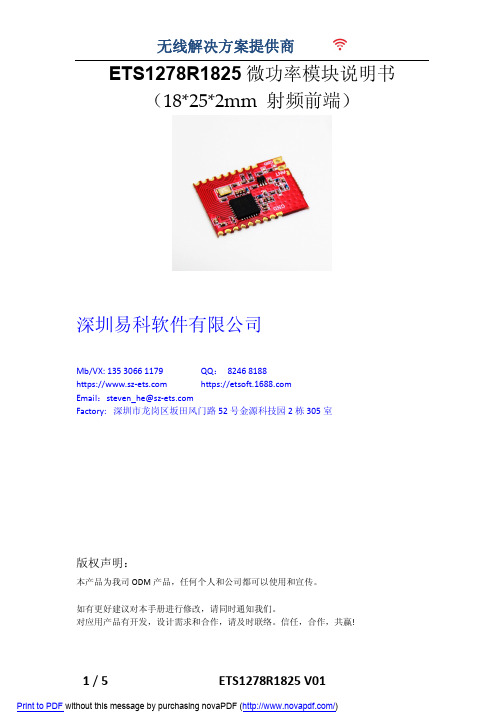
ETS1278R1825微功率模块说明书(18*25*2mm 射频前端)深圳易科软件有限公司Mb/VX:QQ:8246 8188https:// https://Email:Factory: 深圳市龙岗区坂田风门路52号金源科技园2栋305室版权声明:本产品为我司ODM产品,任何个人和公司都可以使用和宣传。
如有更好建议对本手册进行修改,请同时通知我们。
对应用产品有开发,设计需求和合作,请及时联络。
信任,合作,共赢!目录一、 模块介绍二、 产品特点三、 应用范围四、 尺寸与引脚定义五、 技术参数六、 模块应用注意事项七、 常见故障及排除方法八、 客户订制要求一、 模块介绍模块采用SX127x系列收发射频芯片,采用LORA扩频无线射频技术,数字处理技术,高抗干扰,高稳定性和高性价比。
用户只需通过模组提供的SPI数字接口,控制芯片内部寄存器,实现对SX127x 参数配置、无线数据收发等功能。
该模块具有尺寸小,灵敏度高,传输距离远,通讯速率高,延时小。
用户可以根据自己的要求来定制模块尺寸,输出功率,频率段等参数,或者直接将将模块布板到用户的PCB上,提升客户的产品水平和节省成本。
二、 产品特点微功率发射,最大输出20dbm,可通过设置控制发射功率。
工作频段:137MHZ-1020Mhz 等免申请频段,可根据用户的要求定制工作频段。
接收灵敏度最高达-148dBm@1200bps,在天线高度2米时,开阔地无干扰情况下可达3000米。
三、 应用范围无线排队设备,酒店电子门锁、生物识别门禁管理系统智能家居、家庭电器和灯光智能控制医疗和电子仪器仪表自动化控制智能教学设备、婴儿监护、医病房呼叫系统防盗报警,车辆防盗,智能卡,铁路机车远程检测水、电、煤气,暖气自动抄表收费系统或无功补偿及电网监测无线会议表决、打分系统,PDA终端、无线点菜系统LED屏无线传输文字,图片和无线控制,电子衡器、无线吊秤、车辆监测、老化设备检测,工业设备数据无线传输以及工业环境监测视频监控云台控制,门禁考勤读卡器气象/油井/水利设备信息采集以及自然环境检测资产管理和人员区域定位、物流供应链管理。
RDT-GW519 无线4G路由图传模块使用说明书-1690804209.9389808

RDT-GW519无线4G 路由图传模块使用说明书Ver1.0地址:深圳市龙岗区坂田街道贝尔路坂田高新技术工业园微谷C 座829室电话:*************网站: QQ :247868399、910837897邮箱:*************文档RDT-GW519无线4G路由图传模块使用说明书版本号Ver1.0发布日期2020-06-281.产品简介RDT-GW519无线4G路由图传模块采用MTK工业级MT7628NN无线路由器方案,4G 模组采用美格的华为4G方案全网通SLM790工业模组,产品基于4G网络需求研发的高性能优异稳定的无线4G路由通信产品。
产品提供2路100M以太网口、300M WIFI无线接口、UART接口(TTL电平/RS-232/RS-485可选),可以对接多种终端设备,带双网口WAN口/LAN口可选,方案独特,使得产品稳定性得到行业的认可。
支持WEB配置方式,管理方便简单,支持远程云端管理。
它主要应用于行业用户的数据传输业务,支持数据透明传输、VPN、无线桥接、图像传输、设备监控以及无线路由上网等功能。
RDT-GW519无线4G路由图传模块广泛在电力、石油、煤矿、金融、通信、公安、热力、工业控制、气象、水利、交通、市政等环境复杂行业应用。
2.外观和接口接口说明指示灯状态说明名称状态描述WLAN闪烁无线WIFI 已开启熄灭无线WIFI 未开启4G快闪上电后快闪,说明正在执行拨号过程常亮上电后常亮,说明拨号成功熄灭上电后熄灭,说明未识别LTE 模组或SIM 卡或非4G 工作模式系统灯(SYS)熄灭上电熄灭,说明供电不正常或系统没有启动。
慢闪上电后,变为慢闪,说明系统运行正常3.设置准备项目参数WAN 口(ETH0)1个10/100M 自适应WAN 口,内置隔离,支持自动翻转(Auto MDI/MDIX )、4G 模式下为LAN 口LAN 口(ETH4)1个10/100M 自适应LAN 口,支持自动翻转(Auto MDI/MDIX )串口2个串口,UART0为console 、UART1为数据传输口USB 口(PCIE )USB2.0口,接4G 模组.指示灯3个指示灯(SYS 、4G 、WLAN)天线接口2个一代I-PEX 座电源接口5-12V /2A ±0.2V3.1连接设备您可通过以下步骤将你的设备连接到路由器。
深圳海凌科电子HLK-7628N模块硬件手册说明书

深圳市海凌科电子有限公司HLK-7628N硬件手册版本:V1.0修改日期:2017-7-6版权所有@深圳市海凌科电子有限公司目录1.产品简介 (1)1.1.基本参数 (1)2.方框图 (2)2.1.典型应用 (3)2.2.规格 (4)2.3.接口数量 (4)3.电气特性 (5)3.1.供电要求 (5)3.2.射频特性 (5)3.2.1.802.11B11M (5)3.2.2.802.11G54M (5)3.2.3.802.11N MCS7(HT20) (6)3.2.4.802.11N_MCS7(HT40) (6)4.模块引脚定义 (7)4.1.引脚图定义图 (7)4.2.默认引脚图定义 (8)5.模块尺寸图 (10)6.回流焊温度曲线 (11)1.产品简介海凌科电子出品的HLK-7628N模块是一款基于联发科MT7628AN/MT7628NN为核心的低成本低功耗的300M物联网模块。
该模块引出了MT7628NN的所有接口,支持Linux和OpenWrt操作系统及自定义开发,具有丰富的接口和强大的处理器,可以广泛的应用于智能设备或云服务应用等,并可以自由进行二次开发。
1.1.基本参数⏹超强数据处理能力,MCU主频达580MHz⏹300M的无线速率⏹支持802.11b/g/n模式⏹20/40信道带宽⏹支持802.11v⏹支持AP,STA及AP,STA混合模式⏹5个10/100M自适应网口⏹1个USB2.0主机接口⏹多种接口SPI/SD-XC/eMMC⏹丰富的外设接口,SPI,I2C,I2S,PCM,UART,JTAG,GPIO⏹广泛应用于物联网⏹内置强大的PMU⏹支持16个Multiple BSSID⏹支持多种加密方式WEP64/128,TKIP,AES,WPA,WPA2,WAPI⏹支持QoS,WMM,WMM-PS支持多种系统,Linux2.6.36SDK,OpenWrt3.10 2.方框图EthernetUARTGPIOPWMUSB_HOSTSPISPISI2CI2SJTAGEINTSDXCHLK-7628模块架构图2.1.典型应用HLK-7628NHLK-7628N典型外设接口图2.2.规格项目参数备注模块型号HLK-7628N版本V1.0主芯片MT7628AN/MT7628NN内核MIPS24KEc主频580MHz内存DDR2128MB可定制DDR264M/32MB Flash32MB可定制16MB/8MB 温度环境温度:-40℃~85℃使用:10~95%(不凝结)湿度存储:5~95%(不凝结)尺寸18mm×35.2mm×2.8mm2.3.接口数量接口模块具备的接口出厂默认固件支持的接口WiFi标准IEEE802.11b/g/n支持Ethernet接口5个10M/100M自适应1个WAN、4个LAN UART3路2路UART具备透传功能SDIO1路不支持SPI1路不支持I2C1路不支持I2S1路不支持PWM1路不支持GPIO8路以上已定义功能说明:1,模块出厂默认烧写的为我司基于Linux开发的固件;该固件的Ethernet、WiFi、UART0和UART1具有透传功能。
RAK831 Pilot Gateway 设置手册说明书
LORA / LORAWAN TUTORIAL 28.1 Installing Semtech UDP Packet Forwarder for the RAK831 Pilot Gatewayv1.0.0INTRO•A micro SD card is shipped with the RAK831 Pilot Gateway with all software pre-installed as mentioned in Tutorial 28.•In this tutorial I will show you how to install all the required software on a micro SD card.•The result is a bootable micro SD card which can be used in the RAK831 Pilot Gateway.Install Raspbian Lite on micro SD cardDOWNLOAD RASPBIAN LITE•Download Raspbian Lite.Lite is a minimal version of the Raspbian image for the Raspberry Pi.The Lite version has only a command line interface (CLI) and no desktop or GUI of any kind.This means fewer modules will load with the kernel thus less of the Raspberry Pi’s resources are used.https:///downloads/raspbian/•After the Raspbian Lite is downloaded,verify the SHA256 checksum.The checksum is a hash number and is used to verify the integrity of the file. macOS:shasum -a 256 <file>Linux:sha256sum <file>Windows 10:certutil -hashfile <file> SHA256WRITE IMAGE TO MICRO SD CARD•Download and install Etcher.Etcher is a tool for Windows,Mac and Linux for flashing images to SD cards and USB drives.https://www.balena.io/etcher/•Flash the Raspbian Lite onto the micro SD card using Etcher.•Note:If the micro SD card is not formatted,Etcher will format it before writing and verifying the image.ADD SSH FILE ON MICRO SD CARD•The micro SD Card has a /boot partition.On macOS,see: /Volumes/boot•Goto the /boot partition and add an empty file with name:ssh When the Raspberry Pi is rebooted it will look for file “ssh”. When found,it will enable SSH.By default SSH is disabled.After the reboot,the ssh file will be deleted.Get the gateway IP address•Insert the micro SD card into the Raspberry Pi.•Connect the LoRa antenna to the gateway.Never power up the gateway without the LoRa antenna, otherwise this can cause damage to your gateway.•It is not required to connect the GPS antenna because GPS is by default disabled as explained in Tutorial 28.•Connect the gateway to a router using an Ethernet cable.•Power up the gateway using the included power adapter.Do not use a power adapter with less than 2A output.•By default the Raspberry Pi has the hostname raspberrypi gateway routerInternetEthernet cable GPS LoRa antennamicro SD Card•There are several methods to get the gateway IP address,I will only demonstrate 3.•Method 1. Router devices list•Open a browser and navigate to your router’s IP address e.g.http://192.168.1.1The IP address is usually printed on a label on your router or check your router’s manual.•T o access your router’s configuration interface you need its username and password.Check your router’s manual.•Locate the gateway (raspberrypi) and write down its IP address.•Method 2. Resolving <hostname>.local with mDNS•On Raspbian,multicast DNS is supported out-of-the-box by the Avahi service.•If your computer supports mDNS,you can reach your gateway (Raspberry Pi) by using its hostname and the .local suffix.Enter command:ping raspberrypi.local•If your computer does not support mDNS,install the Net Analyzer app (iOS and Android) on your mobile.•Select the Ping option and enter:raspberrypi.local•Method 3. Connect monitor and keyboardgatewayrouterInternetEthernet cableGPSLoRa antennamicro SD CardUSB keyboardmonitorHDMI cable•Y ou will see the login prompt.The default username=pi and password=raspberry •Login with above mentioned credentials.•Enter command:hostname -I•The IP address will be shown,for example:192.168.1.71•On Linux and Mac the SSH command can be used to access the Raspberry Pi.•On Windows 10,SSH can be used or instead use Putty,https://.•T o enable SSH functionality on the Windows 10 PowerShell:- Open Settings- View the Apps- Go to the Manage optional features- Click Add a feature- Select OpenSSH Client- Wait, then reboot•Access the Raspberry Pi.ssh pi@<ip_address_gateway>For example:*************.1.71•The default username=pi and password=raspberryCHECK CURRENT RASPBERRY PI CONFIGURATION •Check time zone.date•Check the disk space.The full space of the micro SD card is used.df -h•Check if SPI is enabled.ls /dev/*spi*SPI is not enabled if you see:ls: cannot access '/dev/*spi*': No such file or directory•Check current language settings.localeRAK831 PILOT GATEWAYRaspberry Pi 3RAK831 concentratorConverter BoardSPISPIGPS AntennaPower supplyLoRa Antenna Led’sGPSPower supplyEthernet MCU4x USBPower ConnectorSX1301SX1257SX1257Configure Raspberry Pi•The Raspberry Pi needs to be configured.I will change:•user pi default password•the language•the time zone•and enable SPI•Open the Raspberry Pi Software Configuration T ool: sudo raspi-config•Change user pi password.Select menu: 1 Change User PasswordNote:For security reasons you must change the user pi default password.•Optionally change the language (default is English:en_GB.UTF-8). Select menu:4 Localisation OptionsSelect menu:I1 Change LocaleScroll the list and use the scrollbar to select.Recommended:xx_XX.UTF-8 UTF-8Press Enter key when done with the selection.In the next screen select the default locale for the system environment. Select for example nl_NL.UTF-8 and press the Enter key.•Change the timezone.Select menu:4 Localisation Options Select menu:I2 Change TimezoneFor example:Geographic area:EuropeTime zone: Amsterdam•Enable SPI.Select menu:5 Interfacing OptionsSelect menu:P4 SPI•This will enable SPI (Serial Peripheral Interface) on the Raspberry Pi.An SPI bus is used to send data between microcontroller(s) and peripherals.In this case sending data to and from the Raspberry Pi and RAK831 concentrator via the Converter Board.•Exit the Raspberry Pi configuration tool.MODIFY .BASHRC FILE•If you changed the language using the raspi-config tool,one extra change is needed. Goto pi’s home directory and edit the .bashrc filecd ~nano .bashrcAt the end of the .bashrc file add the following line with YOUR language choice: export LC_ALL=nl_NL.UTF-8Save the fileREBOOT AND LOGIN RASPBERRY PI •Reboot the Raspberry Pi:sudo reboot•Again access the Raspberry Pi:ssh pi@<ip_address_gateway> password=<your_new_password>VERIFY CHANGES•Check time zone:date•Check the disk space:df -h•Check if SPI is enabled:ls /dev/*spi*Y ou will see:/dev/spidev0.0 /dev/spi/dev0.1•Check current language settings.localeInstall softwareINSTALL SOFTWARE•Upgrade the Raspberry Pi packages:sudo apt-get update && sudo apt-get upgrade -y•Install Git.Git is a distributed version control system.sudo apt-get install git•I have forked https:///RAKWireless/RAK831-LoRaGateway-RPi andsimplified the installation procedure.•The repository https:///robertlie/RAK831-LoRaGateway-RPi contains just a few files.The install.sh script:- Creates the gateway EUI.- Allows the user to set the gateway hostname.- Allows the user to select the region the gateway will operate in.Dependant on the selected region the correct global_conf.json is copied from theconfiguration_files folder.- The local_conf.json is copied from the configuration_files folder and the gateway EUI is set in this file.- Allows the user to set the gateway latitude and longitude coordinates and its altitude. - Installs the Semtech LoRa library and the Semtech UDP Packet Forwarder and build both packages.- Makes the packet_forwarder a service,which means when the Raspberry Pi bootsthe packet_forwarder is started.- Disables the onboard Raspberry Pi bluetooth.•Before you start with the installation procedure,you must know which frequency plan to use in your country.See the list of frequency plans by country list:https:///docs/lorawan/frequencies-by-country.html•The frequency plans can be found at:https:///docs/lorawan/frequency-plans.html•If you know the frequency plan,look at the table and find the corresponding Region.Region Frequency PlanAS1AS920-923AS2AS923-925AU AU915-928CN CN470-510EU EU863-870IN IN865-867KR KR920-923RU-US US902-928INSTALL RAK831-LORAGATEWAY-RPI REPOSITORY •Installation procedure:git clone https:///robertlie/RAK831-LoRaGateway-RPi ~/rak831-loragateway•This repository is installed in:/home/pi/rak831-loragatewayEXECUTE INSTALL SCRIPT•Execute the install script:cd ~/rak831-loragatewaysudo ./install.sh•The following is displayed.Press Enter to keep the default value or change it: Host name [ttn-gateway]: <Enter>Region AS1, AS2, AU, CN, EU, IN, KR, RU, US [EU]: EU Latitude [0]: <Enter>Longitude [0]: <Enter>Altitude [0]: <Enter>•I will keep the default hostname,latitude,longitude and altitude.The latitude,longitude and altitude will be set later in TTN console.INSTALL LORA LIBRARY AND PACKET FORWARDER•As mentioned earlier,the install.sh script installs the following git repositories and build these packages.•Semtech LoRa library (V5.0.1)https:///Lora-net/lora_gateway/opt/ttn-gateway/lora_gateway•Semtech UDP Packet Forwarder (V4.0.1)https:///Lora-net/packet_forwarder/opt/ttn-gateway/packet_forwarderCHECK TTN-GATEWAY SERVICE STATUS •Check ttn-gateway service status:systemctl status ttn-gateway -l•Check if there are no errors and GPS is disabled.Also see:/var/log/syslogglobal_conf.json & local_conf.json•The RAK831 Pilot Gateway can be connected to any LoRa network servers.•In this tutorial the RAK831 Pilot Gateway will be connected to The Things Network server.•The Semtech Packet Forwarder is configured via a file called global_conf.json and if provided an additional file called local_conf.json.•The global_conf.json is the main configuration file and contains for example the LoRa network server address,which uplink and downlink ports to use,which frequencies to use and the TX power LookUp T able (LUT).•The local_conf.json file contains more gateway specific parameters.The local_conf.json will override the settings in the global_conf.json.•The ~/rak831-loragateway/install.sh script creates theglobal_conf.json and local_conf.json files in this folder:/opt/ttn-gateway/packet_forwarder/lora_pkt_fwd•Several other global_conf.json file examples can be found in this folder:/opt/ttn-gateway/packet_forwarder/lora_pkt_fwd/cfg but these files are not used.•The https:///robertlie/RAK831-LoRaGateway-RPi/blob/master/configuration_files/README.md file explains where the global configuration files originates from and what modifications were made to these files.•In Tutorial 28 is explained which parameters to set in the local_conf.json file to enable GPS and for beaconing.In the local_conf.json these parameters are commented out. Uncomment these parameters if needed.•In Tutorial 30 you can find an explanation of all the parameters used in theglobal_conf.json and local_conf.json files.•When the global_conf.json or local_conf.json file is changed,always restart the gateway.•Before restarting the gateway,optionally empty the /var/log/syslog: sudo su> /var/log/syslogexit•Restart the ttn-gateway service:sudo service ttn-gateway restart•Check ttn-gateway service status:systemctl status ttn-gateway -l•Check system log for errors:tail -f /var/log/syslogNEXT STEPS….•The gateway is now running without errors.•Next steps:•Register the gateway to The Things Network,watch: https://youtu.be/bea7g5isD0w?t=1779•Optionally enable WiFi,watch:https://youtu.be/bea7g5isD0w?t=1844。
【产品用户手册】IOT-9608ARM嵌入式工业控制模块

广州致远电子股份有限公司IoT-9608ARM 嵌入式工业控制模块User ManualUM01010101 V1.02Date: 2016/08/01类别 内容关键词 AM3352,Linux ,CAN ,Ethernet ,Serial ,USB摘 要IoT-9608 工控板使用指南修订历史目录1. IoT-9608 工控主板简介 (1)1.1工控主板简介 (1)1.2主板主要接口 (1)1.3硬件参数 (2)1.4软件参数 (2)2. 系统基本操作 (4)2.1开机和登录 (4)2.1.1启动选择 (4)2.1.2串口连接 (4)2.1.3串口登录 (6)2.1.4SSH远程登录 (6)2.2关机 (7)2.3查看系统信息 (8)2.4系统设置 (8)2.4.1网络设置 (8)2.4.2系统时钟 (9)2.5文件传输 (9)2.5.1SSH文件传输 (9)2.5.2NFS 文件传输 (11)2.6U盘使用 (11)2.7SD卡使用 (12)2.8U-Boot交互 (12)2.9串口测试 (12)3. 文件系统 (14)3.1分区描述 (14)3.2支持的文件系统 (14)3.3安装第三方软件 (15)3.4程序开机自启动 (15)4. 应用程序开发 (17)4.1应用程序开发环境构建 (17)4.1.1嵌入式Linux开发一般方法 (17)4.1.2安装操作系统 (18)4.1.3构建交叉开发环境 (18)4.1.4NFS 服务器配置 (19)4.2Hello 程序 (20)4.3GPIO 使用 (21)4.4蜂鸣器使用 (22)4.5串口编程 (22)4.5.1访问串口设备 (23)4.5.2配置串口接口属性 (24)4.5.3获得和设置串口信号线状态 (32)4.6Socket CAN编程 (33)4.6.1初始化CAN网络接口 (33)4.6.2socket can编程 (34)4.6.3示例程序 (37)4.7看门狗使用 (42)4.7.1概述 (42)4.7.2范例 (42)5. 系统恢复和更新 (44)5.1制作SD卡 (44)5.2烧写Linux固件 (44)5.3升级某个固件 (45)5.4全自动升级固件 (46)5.5其它 (46)5.6Tera Term使用说明 (46)6. 免责声明 (49)1. IoT-9608 工控主板简介1.1 工控主板简介IoT-9608是广州致远电子股份有限公司开发的基于AM3352处理器的工控主板,采用“核心板+底板”的结构。
- 1、下载文档前请自行甄别文档内容的完整性,平台不提供额外的编辑、内容补充、找答案等附加服务。
- 2、"仅部分预览"的文档,不可在线预览部分如存在完整性等问题,可反馈申请退款(可完整预览的文档不适用该条件!)。
- 3、如文档侵犯您的权益,请联系客服反馈,我们会尽快为您处理(人工客服工作时间:9:00-18:30)。
MT7628/7688 WIFI模块用户硬件手册
版本:V1.1
概述
本文档主要介绍MT7628/7688 WIFI模块的电气特性、机械尺寸、引脚定义、开发配套资源等。
配套开发板版本
与本模块相配套的开发板版本如下,可购买对应配套开发板,加快开发流程。
适用场景
本模块适合场景众多,如以下场景:
●路由产品
●物联网
●无线通信
●中继
修订记录
修订记录累积了每次文档更新的说明。
最新版本的文档包含以前所有文档版本的更新内容。
目录
1、产品概述 (1)
1.1模块简介 (1)
1.2主要应用领域 (1)
1.3模块特点 (1)
1.4模块基本参数 (2)
2、硬件介绍 (3)
2.1引脚定义 (3)
2.2 电气特性 (6)
2.3 封装尺寸 (7)
2.4 天线 (7)
2.5 开发套件 (8)
3、购买说明(如有具体需求联系客服) (9)
1、产品概述
1.1模块简介
云联芯出品的MT7628/7688 WIFI模块是一款基于MT7628/7688AN的低成本低功耗的物联网模块。
该模块支持Linux和OpenWRT操作系统及自定义开发,是一体化的802.11 b/g/n WIFI解决方案,可以广泛地适用于智能设备和云服务应用等,包括有线转无线、4G转WIFI、无线摄像头、硬AP、路由器、无线音箱、无线存储等。
1.2主要应用领域
●物联网应用
●WIFI智能家居
●WIFI 安防监控
●工业控制
●消费类电子
●有线转无线
●4G转WIFI共享
●无线摄像头
●硬AP
●路由器
●无线音箱
●无线存储
●WIFI移动电源
●便携式移动WIFI热点
1.3模块特点
本模块采用MT7628/7688AN方案,尺寸小,性能稳定。
主要特点如下:
(1)超小体积,长宽仅42mm×32mm。
(2)邮票孔接口,方便安装。
(3)内置陶瓷天线和I-PEX接口。
(4)3.3V单电源供电。
(5)有线+无线路由器方案
(6)支持802.11 b/g/n协议,最高300/150Mbps。
(7)有线支持1WAN或1LAN,10M/100M自适应。
(8)适中的RF功率消耗。
(9)板载64-256MB DDR2内存,8-16MB FLash。
(10)480Mbps高速USB接口。
(11)3路UART(推荐UART0专用于系统Debug)。
(12)TCP转串口。
(13)SD-XC、eMMC、PCM、IIS数字音频接口(192K/24bits)、IIC通讯接口、PWM、SPI master/slave。
(14)丰富的GPIO。
1.4模块基本参数
2、硬件介绍
上电后,电压供应正常蓝灯亮,红灯亮代表WIFI启动成功,即系统正常启动。
2.1引脚定义
带*号前缀红色信号用于系统启动配置,外部不可驱动,不要上拉下拉,会导致启动不成功。
SPI部分引脚顺序以表格为准,图片标记有错误!
更多复用引脚详细情况,可查阅Datasheet。
2.2 电气特性
2.3 封装尺寸
引脚间距为1.27mm(50mil),客户设计PCB时,可联系我司提供封装,可提供AD、PADS、Orcad、Allergo的原理图及PCB封装。
2.4 天线
本模块支持板载陶瓷天线和外置天线。
当客户使用内置天线时,需要注意:
(1)将天线远离金属,至少与周围较高元器件保持10mm 间距。
(2)天线部分不能被金属外壳遮挡,塑料外壳至少保持10mm。
当客户使用外置天线接口,根据IEEE 802.11 b/g/n 标准的要求,外置天线的参数要求如下表所示:
2.5 开发套件
评估开发套件,供客户快速熟悉产品和进行深度应用开发。
3、购买说明(如有具体需求联系客服)
我司可提供的MT7628/MT7688AN WIF模块配置及价格如下:。