ADH吸附式再生空气干燥器说明书
吸附式干燥机 使用手册说明书
吸附式干燥机使用说明书感谢您选用吸附式干燥机。
本《使用手册》为正确的安装、使用的产品维护作了简要的说明。
您应该熟悉与其相关的安全结构,性能,维护和修理方面的说明。
对设备无故障运行的操作,基本的和特殊的安全知识是必须具备的。
使用前请认真阅读本说明书。
请将本手册放在便于查阅的地方。
一、目录二、安全事项说明2.1 你不可以做什么2.2 担保和赔偿责任2.3 持续运行的安全措施2.4 电能的危险性2.5 吸附剂的危险性2.6 在维护、检修和修理工作中的危险性2.7 对操作者的要求三、设备说明3.1 设备的部件3.2 工作原理流程3.3 运输和安装四、开机/停机/卸压五、故障信息和故障排除六、维护和检修附件: 吸附式干燥机控制器说明二、安全事项说明2.1 你不可以做什么不要对设备作任何结构上的改变——对设备作结构上的改变只能由制造商进行。
你在现场所希望对设备所作的任何改变必须先征得制造商的书面认可。
绝不使用非原厂零件——仅使用由制造商提供的原厂备件和配件,对设计和制造非原厂零件来满足设备的安全和操作需求将不被担保。
绝不焊接压力容器或管道——所有在压力容器和管道上的工作,诸如焊接、结构改变、安装等工作都是禁止的。
2.2 担保和赔偿责任由以下一种或多种情况引起的人身伤害和物件损坏不承担索赔要求。
□不适当地使用或操作设备□技术上不正确的安装,起动,运行和维护□当缺陷确实存在时对设备的操作□违背操作手册所给予的运输、储存、安装、运动和维护方面的规定□主动承担对对设备结构上的变更□对已损耗的设备元件未作适当检测□未作恰当的修理□使用非原厂零件2.3 持续运行的安全措施设备安全工作和无故障运行的一个基本的先决条件是熟知和遵守本说明的工作,操作和安全管理,而且还需遵循所有工厂的内部管理。
□在规定的间隔处检查设备外观的损坏□仅允许合适的经训练的人员操作控制器或设备□制造商预设的参数不作保证,如需要作改变,必须先注意已有参数。
干燥器操作说明书
当设定完t3时间值后,可按面板上的“启动/代码”按钮,最高位显示4,表示设定均压时间t4。其余位显示均压时间设定值。按“停止/参数”按钮增加延时值。可使设置值从1逐步增加到30秒,然后再重复进行。
每三个月:
10、前置和后置过滤器芯,检查堵塞情况及可能的损坏,根据需要替换。
11、关闭进/出口阀门或将干燥机旁通,彻底将干燥机系统泄压,打开干燥剂充填口,采样检查干燥剂,如果干燥剂被油污染粉碎,请更换干燥剂。
12、拆下并检查进口气动阀和再生排气阀,清洗和替换磨损的阀座和密封圈。
13、检查气动阀门膜片和气缸是否泄漏或密封件是否磨损。
1.干燥剂扩散器滤网堵塞
2.压缩空气处理量超过额定流量
3.再生气动阀保持打开
4.单向止回阀动作失灵
1.通过吸附筒体压力表和干燥机出口压力表检查
2.采用流量计检测
3.通过手动的方法检查控制气动阀是否正常工作
4.拆下单向止回阀检查
1.更换干燥剂扩散器
2.检查进口气量的情况
3.检查导向气路或电磁阀,根据需要更换
设定完毕,将拨位开关拨向右方,则设定值将被写入E2PROM储存起来,即使断电后仍能保留。如果设置值错误,则“停止/参数”按钮上方的指示灯闪烁,请重新设定参数。
2、 动作时序图
时序图说明:
OA段
AB段
BC段
CO’段
O’A’段
A’B’段
B’C’段
C’O’段
A塔
吸附
静止
再生
均压
干燥器使用说明书

DJKG-A型空气干燥器使用说明书DJKG-A型空气干燥器是东风7型内燃机车为清洁干燥制动系统压缩空气而设的装置,经该装置处理后的压缩空气,进入总风缸可以达到下述净化指标:1.含油率低于10PPM;2.含尘埃的颗粒度不大于20";3.相对湿度低于35%。
采用此装置,将可避免机车空气制动系统中的风缸、管道及各阀类出现凝结水、冰、锈蚀、杂物,以防止由此而发生的制动失灵故障。
一、性能:1.DJKG-A型空气干燥器是与空气压缩机同步工作的单塔无热再生空气干燥装置。
2.DJKG-A型空气干燥器须安装在机车总风缸之前,空压机出气要经过管道冷却以使进入干燥器的空气温度降至低于55C,且比环境温度最高不大于20Co3.DJKG-A型空气干燥器,由滤清筒、再生风缸和排气电磁阀等组成,其结构简单,作用可靠,检修方便,排污性能好。
二、主要技术数据:处理空气量:3~6m3/min工作压力:900KPa吸附剂:。
4~。
7球型分子筛或球形活性氧化铝再生方式:无热、常压进气温度:5~55c三、空气干燥系统的组成及工作原理:1.压缩空气须经过冷却、滤清和干燥三个环节来净化。
空气干燥器要安装在总风缸之前,以解决总风缸及风压系统的排水和锈蚀,同时还可以使空气压缩机达到无负荷情况下启动。
2.DJKG-A型空气干燥器的工作是与空气压缩机的工况相联系的,它的工作状态是通过风泵调压器来控制的。
风泵调压器是将总风缸压力转变为电控信号的装置,当总风缸压力达到800KPa时,调压器发出断电信号,当总风缸压力低于750KPa时,调压器发出通电信号,通断电信号通过中间继电器及接触器来控制压缩机的启动与停止,同时控制空气干燥器的工作。
3.空气的干燥过程是空气压缩机开启后(图一),压缩空气经过冷却管进入滤清筒,将油雾、水分、尘埃过滤后,再进入干燥筒,空气中的水分子被干燥剂吸附后,干燥清洁的压缩空气从干燥筒下端经止回阀进入总风缸,此工作过程为空气的干燥过程。
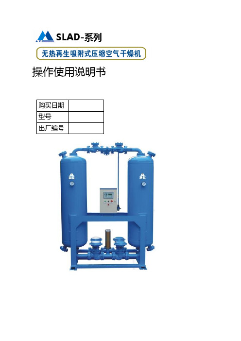
无热再生吸附式干燥器操作使用说明书

杭州超滤净化设备有限公司使用说明书无热再生吸附式干燥机型号:HAD-04—HAD-300 ……………………………………………………………………………、、……………………………………………………………………………………………………………………………请在开机前认真阅读本说明书,并且切实按要求去做;这会给您今后得工作带来长久得方便。
尊敬得用户,为了更好更准确得使用本机器,请您在使用机器前认真阅读本说明书,并严格按照说明书上得使用要求去做。
如果您得机器遇到故障,请认真参照说明书中所列条目对照检修,也可与我们得授权机构或直接拨打售后服务热线8寻求帮助;对您得机器进行及时得保养,将更好得发挥它得性能。
希望本产品在您得工作给您带来便利,谢谢您得支持与合作!目录------------------------------------------------------------------------------产品简介●原理…………………………………………………………、、、2●技术要求……………………………………………………、…2●型号规格及技术参数……………………………………、…、、4安装与维护……………………………………、、…………、、5设备操作………………………………………………………、6●工艺过程…………………………………………………、…、、6●参数设置……………………………………………………、、、6●开机与关机…………………………………………………、、、7故障分析与排除……………………………………………、、、8电气与自动控制——XJK-XG1F无热再生吸附式干燥机控制器使用说明…、、、10●主要功能……………………………………………………、、、10●技术指标……………………………………………………、、、11●使用方法……………………………………………………、、、11●动作时序图……………………………………………………、12●接线方式……………………………………………………、、、12 附录:1 设备首次操作使用方法2电器原理图产品简介●原理HAD系列无热再生吸附式压缩空气干燥机就是一种利用多孔性固体物质表面得分子力来吸取气体中得水份,从而获得较低露点温度、干燥、洁净气体得净化设备。
压缩热再生吸附式干燥机说明书

一、压缩热再生吸附式干燥机的产品简介压缩热再生吸附式干燥机最显著的优点, 是因为它充分地利用了空压机高温排气的热量使吸附干燥剂加热再生,取消了微热再生吸附式干燥机的电加热器,节省了对电力能源的消耗,耗电仅为0.25kW 每小时。
1、 工作原理高温、失饱和的湿空气由压缩机排出后直接进入干燥机,它先进入干燥机的一塔对干燥剂其进行加热,150分钟后,被加热的塔由旁通阀旁通,高温、失饱和的湿空气直接进入后冷却器冷却,再经过气水分离器、液态水份被分离后,再进入另一塔进行干 燥吸附,经过干燥的压缩空气由出口排出,进入使用管网;而由干燥机的出口引一部分气流经过节流孔,完成对再生塔的冷吹,这一小部分气流最后通过消音器排放到大气中。
85分钟后,冷吹结束,开始升压;5分钟后双塔压力均衡,4小时整,双塔干燥机进行另外一塔的再生过程。
如干燥机处于露点监控状态,在升压结束后,干燥机根据出口露点情况切换,以节约耗气量。
压缩热再生吸附式干燥机最显著的优点,是因为它充分地利用了空压机高温排气的热量使吸附干燥剂加热再生,取消了微热再生吸附式干燥机的电加热器,节省了对电力能源的消耗,耗电仅为0.25kW 每小时。
同时由于加热再生时无耗气,最大程度地节约了能量。
它是完全符合我国国策的“节能减排”效应型的吸附式干燥机。
我公司已将此产品大力推向市场,得到了用户的广泛好评。
2、流程图详解压缩热再生吸附式压缩空气干燥机工艺流程图:1、A 塔冷吹气排气气动蝶阀2、B 塔冷吹气排气气动蝶阀3、A 塔进气气动蝶阀(常开)4、B 塔进气气动蝶阀(常开)5、A 塔再生气出气气动蝶阀6、B 塔再生气出气气动蝶阀7、A 塔再生气进气气动蝶阀 8、B 塔再生气进气气动蝶阀9、A 塔冷吹气进气气动蝶阀 10、B 塔冷吹气进气气动蝶阀11、A 塔出气气动蝶阀(常开) 12、B 塔出气气动蝶阀(常开)13、缓冲气气动蝶阀 14、冷吹气节流孔15、加热筒(根据工况设置) 16、冷吹气调节阀17、切换气动蝶阀加热再生阶段:空气进口-阀7-A 塔加热再生-阀5-后冷油分吸附阶段:后冷油分-阀4-B 塔吸附-阀12-空气出口吸附阶段:空气进口-阀17-后冷油分-阀4-B 塔吸附-阀12-空气出口冷吹阶段:空气出口-阀16-电加热器-限流孔板14-阀9-A 塔冷吹-阀1-再生排气出口(三)压缩热再生吸附式干燥机动作时序图空气出口耗气量:3%后冷却器自动排水阀分离器空气进口冷吹阶段A 塔B 塔再生气排出口123546791113810121415平均耗气量<1.25%1617空气出口耗气量:0%(加热阶段不耗气)后冷却器自动排水阀分离器空气进口加热阶段A 塔B 塔再生气排出口1235467911138101214151617。
微热再生吸附式干燥机说明书
微热再生吸附式干燥机说明书(2009-04-28 19:52:29)标签:微热再生干燥机吸附式干燥机吸干机说明书分类:吸附式干燥机说明书1.工作原理概述JHL型微热再生吸干机是根据变压、变温吸附原理,充分利用吸附剂在高压、低温下吸附,低压、高温下脱附的特性,提高单位质量内的吸附剂的吸附量,从而达到深度干燥压缩空气的目的。
它具有无热再生(PSA法)吸干机结构简单,自动化程度高和有热再生(TSA法)吸干机耗气量少,深度解吸之优点。
能够避免无热再生吸干机耗气量大、切换频繁和有热再生吸干机结构庞大复杂、耗电量大的弱点,其综合指标具有明显的优势。
JHL型微热再生吸干机采用双塔结构,一塔在高压、常温下吸附空气中的水分,另一塔在低压、高温下用部份干燥空气使吸附塔中的吸附剂再生,经过一定时间,两塔切换,这样就保证了干燥压缩空气的连续供应。
每个塔的实际工作过程分为三个阶段:吸附——再生(包括加热再生和冷却再生)——充压。
2.工艺流程说明JHL型吸干机的工艺流程如下图所示,压缩空气通过进气阀IA进入吸附塔A,空气被干燥。
干燥后的空气经止回阀CA到达出口,其中有一部分空气作为再生气在到达出口前从气流中分出,经再生气调节阀RV的流量控制,进入到加热器H中,在加热器内再生空气被加热,温度上升,再经止回阀OB流入吸附塔B。
吸附塔B内有上半个周期吸附下来的水分,再生气带走这些水分并经再生阀RB 和消声器MF排空,此为加热再生阶段。
随着加热时间的延长,B塔内的温度不断上升,经过一定时间,加热器断电,再生空气冷却,此为冷却再生阶段。
根据设定的循环周期,确定再生气流的吹扫时间。
这以后,再生阀RB关闭,吸附塔B开始升压直到两塔压力平衡。
升压需要一定的时间,以保证两塔压力均衡,否则可能引起出口处压力波动。
半个循环周期后,进气阀IA关闭,同时进气阀IB打开。
考虑到阀的动作时间,6秒后生再生阀RA再打开。
现在吸附塔B开始干燥空气,而吸附塔A则进入再生状态,这样就完成了一次切换动作。
阿普达微热再生型吸附式压缩空气干燥器

目录安全总则 (2)1.0概述 (3)1.1原理 (3)1.2工作流程 (4)2.0型号及主要技术参数 (5)3.0安装 (6)3.1位置 (6)3.2配管 (6)3.3电源及配线 (6)4.0运行 (6)4.1调整再生气流阀 (6)4.2确定循环周期 (7)4.3开机与关机 (7)5.0电器控制 (7)6.0维护、保养与检修 (9)6.1吸附剂更换 (9)6.2确保吸附剂干燥性 (9)6.3控制气过滤器——滤芯更换 (9)7.0常见故障及处理方法 (11)安全总则1、微热再生型吸附式压缩空气干燥器是带有压力容器的设备,因此工作压力绝不能超过铭牌上标明的最高工作压力。
2、微热再生型吸附式压缩空气干燥器在电力驱动下运行,请按国家电力标准进行安装。
3 、在进行任何电气检修工作前,务必切断电源。
4、在进行任何阀件检修工作前,务必关闭进出设备压缩空气阀门,释放压缩空气的压力,待压力泄完后,再进行下一步操作。
1.0概述1.1原理微热再生型吸附式干燥器由两个充满干燥剂的吸附塔和一个加热器组成,干燥剂吸收水份附着在其表面。
双塔通过气流切换开关,交替地进行干燥和再生,使干燥剂可以循环使用。
运用变压吸附微热再生原理的吸附干燥器中,一部分干燥后的空气,即净化空气,借助于调节阀调节到接近大气压力后再加热到80℃~100℃,通入另一塔,使此塔中的干燥剂再生,压力温度的变化使膨胀后的低压空气变得非常干燥,这部分净化了的干燥空气使吸湿后达到饱和状态的干燥剂脱湿再生,并把吸出的水份带出干燥器。
1.2 工作流程中小立方流程图2.0主要技术参数进气温度:≤45℃进气压力:0.7~1.4MPa进气含油量:≤0.1PPM ;1.4放空阀2.3进气阀; 5.6消声器7.8进气分配器; 9.10吸附桶11.12出气分配器; 13.14再生阀15.17左.右塔压力表; 16再生压力表 18节流孔板; 19再生气调节阀 20.21出气阀; 22加热器23温控探头再生气耗量:7% 成品气露点:≤-20--40℃工作周期:10-60min3.0安装3.1位置3.1.1微热再生型吸附式干燥器应安装在四周通风良好、空气洁净的建筑物内。
ADH NETCOM 自动空气干燥器 DC 双冗余电源模块更换说明说明书
NETCOM®MODEL ADHAUTOMATIC AIR DEHYDRATOR WITH ETHERNETADH® NETCOM™ AUTOMATIC AIR DEHYDRATOR DC DUAL REDUNDANT POWER SUPPLY MODULEREPLACEMENT PROCEDUREReplacement Kit Part Number 24095Document Part Number 24107SAFETY INFORMATION AND WARNINGSAbnormal Odor or SmokeIn the event of smoke or a burning orabnormal odor, immediately interruptpower to the ADH NETCOM with thePOWER switch at the rear of the unit,unplug the unit, or turn off the circuitbreaker controlling the outlet. Notethat only the AC model of the ADHNETCOM has an ON / OFF switch.Lethal Voltages PresentLethal voltages are present inside theADH NETCOM. Service should beperformed by qualified personnelonly. There are no user serviceablecomponents inside the chassis.PneumaticsEach of the air pumps inside the ADHNETCOM automatic air dehydrator iscapable of generating as much as 24psig (1,655mbar). Other attached dryair sources may be capable ofgenerating even higher pressures.Proper safety practice requirestreating all pneumatic componentswith care. Always vent the system toatmospheric pressure before servicingpneumatic components.Rack MountingBefore and after rack mounting theADH NETCOM, ensure that the rackis stable. Mounting of the ADHNETCOM into a rack should be suchthat a hazardous condition is notcreated due to uneven mechanicalloading. Verify that adequate airflow and power source capacity isavailable to the unit. Ensure that theADH NETCOM maximum operatingtemperature of 130°F (55°C) will notbe compromised by othercomponents in the rack. Ensurereliable earthing of the ADHNETCOM.ADH NETCOM DC DUALREDUNDANTPOWER SUPPLY MODULEREPLACEMENT PROCEDUREThis procedure addresses the removal and replacement of the DC Dual Redundant Power Supply Module in an ADH NETCOM Automatic Air Dehydrator with DC Dual Redundant Power. It is recommended to read the entire procedure prior to beginning work.INVENTORY LISTIdentify the following items in this kit prior to beginning work. TOOLS REQUIREDThe following tools are needed to perform this procedure:•5/16” Nut driver•Small flat blade screwdriver•Needle nose pliersItem NumberPartNumberItemQuantityItemDescription1 23224 1 DC Dual Redundant Power Supply Module 224107 1 Instruction Manual (this document)DC DUAL REDUNDANT POWER SUPPLY MODULEREMOVAL AND REPLACEMENTTo replace the DC Dual Redundant Power Supply Module (23224) in an ADH NETCOM with DC Dual Redundant Power,perform the steps below. Refer to Figure 1.Figure 1. THE ADH NETCOMAUTOMATIC AIR DEHYDRATORDC DUAL REDUNDANT POWER SUPPLYMODULE.NOTE:As its name implies and as shown in Figure 1, the DC Dual Redundant Power Supply Module is comprised of two halves, wired to each other in parallel. Follow this procedure as written, disconnecting then connecting only those electrical leads specified in this procedure. Do not disconnect any of the wires connecting either half of the supply module to the other half as doing so will adversely impact the function, integrity, and electrical continuity of the redundant supply module.1.Shut off DC unit power by shutting offthe external power supply. Ifpossible, move the dehydrator to awork table.2.Remove both top machine panels.Retain the mounting hardware.3.From the far right side of the leftbank of supply module electricalleads, disconnect the white/red andwhite/black striped leads. Refer toNumber 1 of Figure 2. To disconnectthe lead, unscrew the set screw aboveit, then gently remove the lead fromthe terminal. Remove both the white/red and the white/black striped leads.4.From the far right side of the rightbank of supply module electricalleads, disconnect the red/white andblack/white striped leads. Refer toNumber 2 of Figure 2. To disconnectthe lead, unscrew the set screw aboveit, then gently remove the lead fromthe terminal. Remove both the red/white and the black/white stripedleads.Figure 2. DC DUAL REDUNDANT POWER SUPPLY MODULE LEFT-SIDE TERMINALS.Disconnect each lead by loosening each set screw,then gently removing the lead.1 25.From the far left side of the PC board terminal block, disconnect the red and black electrical leads. Refer to Figure 3. To disconnect the lead,push in on the orange release tab under the lead, then gently remove the lead from the terminal. Remove both the red and black leads.Figure 3. THE PC BOARD TERMINALBLOCK. Unlike the first two pairs of electrical leads in steps 3 and 4, disconnect the black and red electrical leads in step 5 from the PC board terminalblock.Press in on the orange release tab under the lead,then gently disconnect the lead. Repeat for the other lead.6.Using the nut driver, remove the two nuts and lock washers securing the existing power supply module to the chassis and remove the module.Refer to Figure 4.Retain the mounting hardware.Figure 4. POWER SUPPLY MODULE MOUNTING HARDWARE (2 places).7.Install the new power supply module onto the Pem ® studs from which the original supply module was removed.Secure in place using the two sets of nuts and lock washers removed in step 6.Torque to 10 in/lb.8.Connect the pair of solid red and black leads running from the new power supply module to the two terminals on the far left side of the PC board terminal block from which the original leads were disconnected in step 5.Refer back to Figure 3. Connect the leads with the black lead on the left and the red lead on the right.9.Connect the red/white and black/white striped leads from the cable bundle to the two far right terminals on the righ side of the new power supply module from which the original leads were disconnected in step 4.Refer back to Figure 2. Connect the leads with the red/white lead on the left and the black/white lead on the right and secure in place by tightening the set screw from above.10.Connect the white/red and white/black striped leads from the cable bundle to the two far right terminals on the lef side of the new power supply module from which the original leads were disconnected in step 3.Refer back to Figure 2. Connect the leads with the white/red lead on the left and the white/black lead on the right and secure in place by tightening the set screw from above.11.Reinstall the machine top panels using the hardware removed in step 2.12.Restore machine power.QUESTIONS AND COMMENTS For technical help, questions, or comments concerning this or any ETI, Inc., product, contact the Customer Service Department between 8:00 a.m. and 5:00 p.m. EST.DISCLAIMERETI, Inc. makes no representations or warranties, either expressed or implied with respect to the contents of this publication or the products that it describes, and specifically disclaims any implied warranties of merchantability or fitness for any particular purpose. ETI, Inc. reserves the right to revise this publication and to make changes and improvements to the products described in this publication without the obligation of ETI, Inc. to notify any person or organization of such revisions, changes or improvements. No part of this manual may be reproduced or translated in any form or by any means, electronic or mechanical including photocopying and recording, for any purpose without the express written consent of ETI, Inc.The ETI logo, We Manage Heat, and ADH are registered trademarks of ETI, Inc. NETCOM is a trademarknc. NETCOM isCopyright © 2012 ETI, Inc. All rights reserved.。