蒂森I型诊断仪最新说明书
蒂森I型诊断仪使用说明书
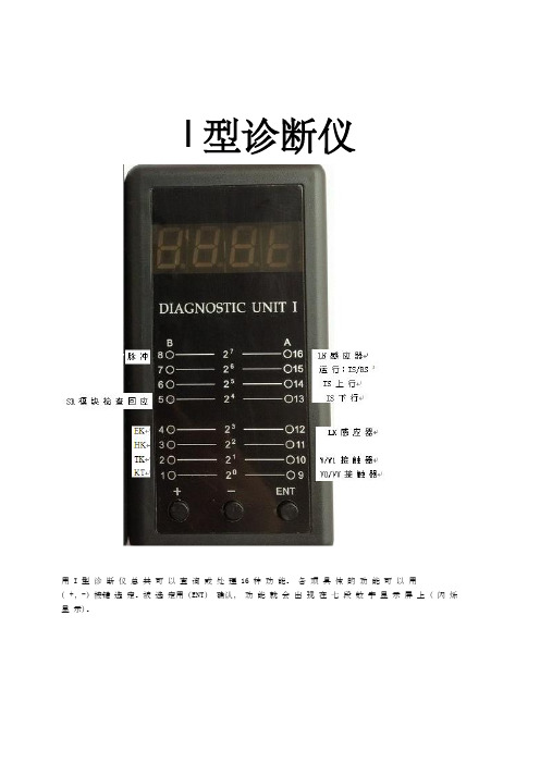
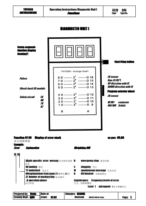
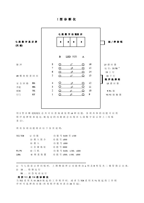
I型诊断仪I 型 诊 断 仪七 段 数 字 显 示 屏起 / 停 按 钮 (闪 烁) 脉 冲 感 应 器运 行:IS/RS 2)上 行 SR 模 块 检 查 回 应 下 行程 序 选 择 轮 安 全 回 路 感 应 器接 触 器接 触 器用I 型诊断仪总共可以查询或处理16种功能。
各项具体的功能可以用程序选择轮来选定。
被选定的功能就会出现在七段数字显示屏上(闪烁显示)。
所有各项功能将在以下各页说明: TCI/TCM 1) 功 能 功 能 号 0100 至 1400 2) 教 入 简 介 功 能 号 1500 3) 教 入 功 能 号 1500 4) 存 储 地 址 功 能 号 0000 F2/F3 5) 门 机 功 能 号 0100, 1400, 1500 LSM1 6) 称 重 装 置 功 能 号 1300, 1400, 1500 ________________________________________________________________1) 当七段显示屏闪烁时,上图侧面所示功能将由A 列及B 列发光二极管指示出来。
2) IS ... 检修运行RS ... 应急电动运行用於TCI 及TCM 的诊断仪当TCI 采用从04.86/3版起的工作程序时,或者当TCM 采用从V1版起的工作程序时可选择的功能 (有效程序版本表自26页起)。
EK HKTK KT使用方法•将 I 型诊断仪插入 CPU,必定出现功能显示 (闪烁)。
用程序选择轮选定所需的功能。
•只有当七段显示屏闪烁时,才可能从一种功能转换到另一种功能。
•要退出所选功能,可将程序选择轮转动一挡,再按下起 / 停钮 > 2 秒。
• 要 从 教 入 功 能 退 出 时,可 以 通 过 AF 00 或 者 将 主 开 关 断 开 再 接 通。
• 下 述 的 关 於 I 型 诊 断 仪 的 解 释 和 功 能 说 明 适 用 於 所 有 的 从 04.86.3 版 起 的 工 作 程 序。
蒂森调试

功能15 00教入适用于控制装置 TCI 和 TCM 配 FV 驱动、受控及调速液压驱动以及 Isostop 16M 驱动根据有关的控制装置型式和驱动装置型式,下列 AF 功能可能以不同的顺序出现在诊断仪的显示屏 (七段数字显示) 上。
特定的 AF 功能只能在特定的驱动型式或用户特性中起作用 (参见电梯设备的数据表)。
只有当应急电动运行开关 (或检修运行开关) 闭合以及七段数字显示屏闪烁时,才可能进入教入模式。
进入教入模式程序隐设值(不修改参数)程序隐设值(修改参数)对 TCM 装置的楼层编码(参见 MA 12 6510.063第 4 节) 15 0015 AFAF 0CAF 0d0A XX0b XX1A XX1b XX用程序选择轮选择并用应急电动运行开关接通操动按钮 (或逆时针转动选择开关),将出现 AF 0d 或 AF 10.不以特别输入的参数值来修改,程序隐设值将被置入 TCM (例如这对于自动楼层编码就很有意义)。
按动按钮后,隐设值将被自动地编入程序:-如使用 MW1 或 MD1 电路板,调速驱动的控制参数。
-门等待时间及再开门时间 (各为 3 秒)。
-越程减速及减速检测的动作点。
-下越程及上越程补偿 (平层校正) 将被设至零。
-SR 模块的作用和不作用以及制动器检测开关,等。
用 AF 0C 或 AF 0d,楼层将自动编码到 MS2 电路板上。
-主门侧和后门侧。
主门侧 XX 楼层处楼层编码故障:后门侧 XX 楼层处楼层编码故障:电路板 MS2 尚未装入井道,或井道总线未接上,或总线中断。
当有故障时退出教入模式 (主开关断/合)。
再进入后,用程序选择轮跳过 AF 0d 功能并继续做教入。
故障在任务表 A (故障出在定单处理)。
故障在任务表 B (故障出在定单处理)。
井道教入AF 10 将轿厢移动到底层以下如图示。
AF 11 EE 0A 感应器和脉冲发电机的 LED 必须发光LK 感应器A 列 LED 12LN 感应器A 列 LED 16脉冲发电机 B 列 LED 8 (闪烁,例如轿厢用手轮移动时)按动按钮将显示如下:断开应急电动运行开关并按动按钮。
诊断仪使用
I型诊断仪用 I 型诊断仪总共可以查询或处理 16 种功能。
各项具体的功能可以用( +,-)按键选定。
被选定用(ENT)确认,功能就会出现在七段数字显示屏上 ( 闪烁显示)。
所有各项功能将在以下各页说明:TCI/TCM 1) 功能功能号 0100 至 14002) 教入简介功能号 15003) 教入功能号 15004) 存储地址功能号 0000F2/F3 5) 门机功能号 0100, 1400, 1500LSM1 6) 称重装置功能号 1300, 1400, 1500________________________________________________________________1) 当七段显示屏闪烁时,上图侧面所示功能将由 A 列及 B 列发光二极管指示出来。
2) IS ... 检修运行RS ... 应急电动运行用於TCI 及 TCM的诊断仪当 TCI 采用从 04.86/3 版起的工作程序时,或者当 TCM 采用从 V1 版起的工作程序时可选择的功能 (有效程序版本表自 26 页起)。
使用方法•将 I 型诊断仪插入 CPU,必定出现功能显示 (闪烁)。
用程序选择轮选定所需的功能。
•只有当七段显示屏闪烁时,才可能从一种功能转换到另一种功能。
•要退出所选功能,可将程序选择轮转动一挡,再按下起 / 停钮 > 2 秒。
•要从教入功能退出时,可以通过 AF 00 或者将主开关断开再接通。
•下述的关於 I 型诊断仪的解释和功能说明适用於所有的从 04.86.3 版起的工作程序。
适用的工作程序列於从 26 页开始的关於功能 14 00 的说明中。
功能01 00显示故障堆栈1) 用程序选择轮选择功能01 00。
2) 按起/ 停纽;最後发生的故障的代码就显示在七段显示屏上。
3) 再继续按起/ 停纽,就依次显示倒数第二次、第三次... 等等故障的代码。
4) 要退出此项功能,可将程序选择轮再转一挡并持续按下按钮超过2 秒。
蒂森控制板操作器说明书

DIAGNOSTIC UNIT IFunction 01 00 Display of error stack as per:05.00显示故障堆栈 Example:ErrorExplanationWeighting BW任务特N emergency stop 紧急停梯 landing 楼层S stopping 停止undefined 未定义M spontaneous message 自发信息 explanations from page 21 解释21页B lift blocked 电梯被锁定ZZ Number of marking flag 标志编号..B operation phase 运行阶段Significance: Frequency levels of error: 含义:故障频繁度Level 1 infrequent 1度不频繁1) can be suppressed with switch 6S1 on circuit board MZ or with switch S5 on circuit board MZ1.1) Dependenton the function involved, reset can either mean emergency stop following by adjusting run or stopping of the lift installation2) Handshake is defined as cyclical data exchange (telegram) between two data carriers.1) SR module can be masked out via teach-in mode function AF 0d. Running-open operation and re-levelling with door open is not possible.1) Error from TCI work program 03.89/7 – no longer used.2) Error 35 00 and 3b 00 can no longer occur from work program 02.87/4 and error 36 00 can no longer occur from 06.95/25.1) SR module can be masked out through teach-in-mode function AF 0d. N Runnin-open operation andre-levelling with open door not possible.2) 0C 04 to 0C 0C leads also to stopping, if not provided otherwise in the lift-specific EPROM !1) If errors 65 00 to 74 00 occur more than 3 times, error 4F 00 will follow afterwards, which leads tospontaneous message and stopping1) DSP is the digital signal processor in the CPI controller2) Handshake is defined as cyclical data exchange (telegram) between two data carriers.Explanations of the existing error code numbers04 NN TCI control – Interrogation of ZSE solenoid switchesNN is represented as a hexadecimal number; in the event of errors, it indicates the number of ZSE switches (no other than the ZSE switch of the car position may be actuated).04 00 applies to ZSE 25 t o ZSE 3104 00 applies to ZSE 17 t o ZSE 2404 00 applies to ZSE 9 to ZSE 1604 0C applies to ZSE 1 to ZSE 8Example: 0 4 0 CHexadecimal number 0C∣∣Binary number 0 0 0 0 1 1 0 0∣∣∣∣∣∣∣∣assigned ZSE switch 8 7 6 5 4 3 2 1The example shows that ZSE switches ZSE3 and ZSE4 (in 3. and 4. landing) havebeen activated. (Also compare hexadecimal code in part 4, page 2)04 NN TCM control – Interrogation of ZSE solenoid switchesIf ZSE switches are closed in the third and fourth landing, the TCM controlwill file two errors: 04 03 und 04 0406 XX TCI control–Door locking not possible (from work program version 08.91/9)The lift will be put out of service for 15 min. after 3 unsuccessful doorlocking attempts. A new locking attempt will be initiated after expiry ofthis period of time.XX = StandortDoor variant – hinged door:A new locking attempt will also be made within these 15 min. after opening ofthe landing door (TK open) and closingit again (TK closed).Door variant D4 (with mechanical locking device)A start attempt will be enabled within 15 min., as soon as the controlreceives the bolt contact.06 XX TCM control–Door locking not possibleIf open bolt contact is recognized in the command chain preceding theposition the following error will follow14 XX (XX = bolt contact main side)18 XX (XX = bolt contact rear side)09 NN Car will be blocked in the landing >4 minExample LED Signal name (LED display on diagnostic unit Irow A)0 KKD0 LSD1 KK O.K.1 LS O.K.0 TSUD0 TSOD0 TSU1 TSO activatedFor LEDs and signal names see Operating Instructions of Diagnostic Unit I,function 05 00, column 0d (display of predefined memory locations, from page25).19 NN Door zone not detectedExample 1 9 C 81 VR1 A5A0 TO0 TU1 FL0 FS0 FO0 FUIn the operation phase STOP (lift at standstill), the CPU recognizes that thedoor zone calculated from the landing vanes was left.For LEDs and signal names see Operating Instructions Diagnostic Unit Ifunction 05 00, column 05 (display of predefined memory locations,from page25)1d NN Emergeny stop (wrong run direction)No run direction or both run directions were produced with the run contactoractivated and the brake disengaged.For LEDs and signal names see Operating Instructions, Diagnostic Unit I,function 05 00, column 05 (display of predefined memory locations from page25).In case of error 1d C8 the processor outputs the signals VR, A5A and FL (butwithout run directions); compare above representation of error 19 NN1E NN Deceleration not effectiveBinary display of car positionIt will be examined whether deceleration has been initiated already onreaching the marked terminal landing vanes.The position is indicated by the five bitst 20 to 25 as binary number.Example:27FO (run direction UP)26FU activated (run direction DOWN)252423Position (hexadecimal number converted into22binary number)211 201 E 9d: bits 20 to 27 stand for landing 29, therefore only run direction UPexists, since 26 = 0 and 27 = 1, and consequently 9 d will follow.Function 02 00 Display of order number (fromTCI work program version 06.88/6 and with TCM)显示定单号码(从TCI 06.88/6版工作程序起以及TCM梯)Example: Order No.: 27 70 06 42 10∣∣∣∣∣LED 5 12 3 10 1B A B A BFunction 03 00 Position indicator (decimal)楼层显示(十进制)Function 04 00 Operation phaseFunction 05 00 Display of specified memory locations1) Set function 05 00 with program selector wheel2) Press start-stop button3)Select desired column in 7-segment display with program selector wheelExample: Column 0d is desired. For example, select 0C 0d in 7-segment display, then left LED row B applies to column 0C and right LED row A applies to column0d, etc.4) Interrogate LED display (compare overview and signal description)5) Exit: press start-stop button for longer than 2 s.The LEDs listed in the table will light on selecting the respective column (Col) :1) Error markingExtension of columns for TCM control with MC1 or MC2 circuit boards1) pulses are counted dependent on the run direction (20 to 27 is displayed in LED row A/B)1) will be displayed as hexadecimal number in LED row A. Example: 09 in LED row A LEDs 0000 1001 light up2) displays last failure before current failure cause column 2C. Is displayed in hexadecimal numbers as in column 2C1) MF3 (VA) stands for circuit board MF3 with double-sided insertion 1) MF3 (VA) stands for circuit board MF3 with double-sided insertion1) MF3 (VA) stands for circuit board MF3 with double-sided insertion1) not assigned currently.Function 07 00 Display of parameters of CPI controller (only with TCM controls) 显示CPI。
蒂森诊断仪--使用说明书【功能教入-存储地址】
N S M B
紧 停 自 电
急停梯 止 发信息 梯被锁定
故障代码
含 义: 故 障 频 度: 1度- 不频繁发生 10 度 - 频 繁 发 生
故障码
01 XX
故障说明
SR 模 块 检 查 回 应 安 全 回 路
LK 感 应 器 2) 行:IS/RS 上 行 下 行 序 选 择 轮 感 应 器
W/W1 接 触 器 VO/VU 接 触 器
Unternehmensbereich F
诊断仪-使用说明书
功 能
Telelift - Gruppe, Puchheim
攔 d e r t e c h n i k N e u h a u s e n
W erk Grenzach
AGV Techn.Inc., Technik u. Vertrieb Neuhausen Salt Lake City
Translogic - Gruppe, Denver
W alther Rohrposttechnik GmbH,
I 型 诊 断 仪
仪器编号:
W esterstede (49%)
MA partNo.
6510
Type
046
Type No.
THYSSEN AUFZÜGE
W erk Grenzach
AGV Techn.Inc., Technik u. Vertrieb Neuhausen Salt Lake City
Translogic - Gruppe, Denver
W alther Rohrposttechnik GmbH,
F2/F3 LSM1
________________________________________________________________
蒂森诊断仪完全版
I型诊断仪I型诊断仪七段数字功能显示1)七段数字显示屏起 / 停按钮(闪烁)脉冲 27 LN 感应器26 运行:IS/RS 2)25 IS 上行SR 模块检查回应 24 IS 下行程序选择轮安全回路 23 LK 感应器2221 W/W1 接触器20 VO/VU 接触器用 I 型诊断仪总共可以查询或处理 16 种功能。
各项具体的功能可以用程序选择轮来选定。
被选定的功能就会出现在七段数字显示屏上 ( 闪烁显示)。
所有各项功能将在以下各页说明:TCI/TCM 1) 功能功能号 0100 至 14002) 教入简介功能号 15003) 教入功能号 15004) 存储地址功能号 0000F2/F3 5) 门机功能号 0100, 1400, 1500LSM1 6) 称重装置功能号 1300, 1400, 1500________________________________________________________________1) 当七段显示屏闪烁时,上图侧面所示功能将由 A 列及 B 列发光二极管指示出来。
2) IS ... 检修运行RS ... 应急电动运行用於TCI 及 TCM的诊断仪当 TCI 采用从 04.86/3 版起的工作程序时,或者当 TCM 采用从 V1 版起的工作程序时可选择的功能 (有效程序版本表自 26 页起)。
使用方法•将 I 型诊断仪插入 CPU,必定出现功能显示 (闪烁)。
用程序选择轮选定所需的功能。
•只有当七段显示屏闪烁时,才可能从一种功能转换到另一种功能。
•要退出所选功能,可将程序选择轮转动一挡,再按下起 / 停钮 > 2 秒。
•要从教入功能退出时,可以通过 AF 00 或者将主开关断开再接通。
•下述的关於 I 型诊断仪的解释和功能说明适用於所有的从 04.86.3 版起的工作程序。
适用的工作程序列於从 26 页开始的关於功能 14 00 的说明中。
功能01 00显示故障堆栈截至01.961) 用程序选择轮选择功能01 00。
蒂森控制板操作器说明
DIAGNOSTIC UNIT IFunction 01 00 Display of error stackas per: 05.00显示故障堆栈 Example:ErrorExplanationWeighting BWerror messag 任务特性故障Nemergency stop 紧急停梯楼层S stopping 停止未定义M spontaneous message 自发信息 e xplanations from page 21 解释见21页 B lift blocked 电梯被锁定 Number of marking flag 标志编号Significance: Frequency levels of error:含义:故障频繁度Level 1 infrequent 1度不频繁发生1) can be suppressed with switch 6S1 on circuit board MZ or with switch S5 on circuit board MZ1.1) Dependenton the function involved, reset can either mean emergency stop following by adjusting run or stopping of the lift installation2) Handshake is defined as cyclical data exchange (telegram) between two data carriers.1) SR module can be masked out via teach-in mode function AF 0d. Running-open operation and re-levelling with door open is notpossible.1) Error from TCI work program 03.89/7 – no longer used.2) Error 35 00 and 3b 00 can no longer occur from work program 02.87/4 and error 36 00 can no longer occur from 06.95/25.1) SR module can be masked out through teach-in-mode function AF 0d. N Runnin-open operation and re-levelling with open door notpossible.2) 0C 04 to 0C 0C leads also to stopping, if not provided otherwise in the lift-specific EPROM !1) If errors 65 00 to 74 00 occur more than 3 times, error 4F 00 will follow afterwards, which leads to spontaneous message andstopping1) DSP is the digital signal processor in the CPI controller2) Handshake is defined as cyclical data exchange (telegram) between two data carriers.Explanations of the existing error code numbers04 NN TCI control – Interrogation of ZSE solenoid switchesNN is represented as a hexadecimal number; in the event of errors, it indicates the number ofZSE switches (no other than the ZSE switch of the car position may be actuated).04 00 applies to ZSE 25 to ZSE 3104 00 applies to ZSE 17 t o ZSE 2404 00 applies to ZSE 9 to ZSE 1604 0C applies to ZSE 1 to ZSE 8Example: 0 4 0 CHexadecimal number 0C∣∣Binary number 0 0 0 0 1 1 0 0∣∣∣∣∣∣∣∣assigned ZSE switch 8 7 6 5 4 3 2 1The example shows that ZSE switches ZSE3 and ZSE4 (in 3. and 4. landing) have been activated.(Also compare hexadecimal code in part 4, page 2)04 NN TCM control – Interrogation of ZSE solenoid switchesIf ZSE switches are closed in the third and fourth landing, the TCM control will file two errors:04 03 und 04 0406 XX TCI control–Door locking not possible (from work program version 08.91/9)The lift will be put out of service for 15 min. after 3 unsuccessful door locking attempts. A newlocking attempt will be initiated after expiry of this period of time.XX = StandortDoor variant – hinged door:A new locking attempt will also be made within these 15 min. after opening of the landing door(TK open) and closingit again (TK closed).Door variant D4 (with mechanical locking device)A start attempt will be enabled within 15 min., as soon as the control receives the bolt contact.06 XX TCM control–Door locking not possibleIf open bolt contact is recognized in the command chain preceding the position the followingerror will follow14 XX (XX = bolt contact main side)18 XX (XX = bolt contact rear side)09 NN Car will be blocked in the landing >4 minExample Signal name (LED display on diagnostic unit I row A)0 KKD0 LSD1 KK O.K.1 LS O.K.0 TSUD0 TSOD0 TSU1 TSO activatedFor LEDs and signal names see Operating Instructions of Diagnostic Unit I, function 05 00,column 0d (display of predefined memory locations, from page 25).19 NN Door zone not detectedExample1 VR1 A5A0 TO0 TU1 FL0 FS0 FO0 FUIn the operation phase STOP (lift at standstill), the CPU recognizes that the door zonecalculated from the landing vanes was left.For LEDs and signal names see Operating Instructions Diagnostic Unit I function 05 00, column05 (display of predefined memory locations,from page 25)1d NN Emergeny stop (wrong run direction)No run direction or both run directions were produced with the run contactor activated and thebrake disengaged.For LEDs and signal names see Operating Instructions, Diagnostic Unit I, function 05 00, column05 (display of predefined memory locations from page 25).In case of error 1d C8 the processor outputs the signals VR, A5A and FL (but without rundirections); compare above representation of error 19 NN1E NN Deceleration not effectiveBinary display of car positionIt will be examined whether deceleration has been initiated already on reaching the markedterminal landing vanes.The position is indicated by the five bitst 20 to 25 as binary number.Example: 1 E 9 d0 27FO (run direction UP)1 26FU activated (run direction DOWN)0 251 241 23Position (hexadecimal number converted into1 22binary number)0 211 201 E 9d: bits 20 to 27 stand for landing 29, therefore only run direction UP exists, since 26 = 0 and 27= 1, and consequently 9 d will follow.Function 02 00 Display of order number (fromTCI work program version 06.88/6 and with TCM)显示定单号码(从TCI 06.88/6版工作程序起以及TCM梯)Example: Order No.: 27 70 06 42 10∣∣∣∣∣LED 5 12 3 10 1B A B A BFunction 03 00 Position indicator (decimal)楼层显示(十进制)Function 04 00 Operation phaseFunction 05 00 Display of specified memory locations1) Set function 05 00 with program selector wheel2) Press start-stop button3)Select desired column in 7-segment display with program selector wheelExample: Column 0d is desired. For example, select 0C 0d in 7-segment display, then left LED row B applies to column 0C and right LED row A applies to column 0d, etc.4) Interrogate LED display (compare overview and signal description)5) Exit: press start-stop button for longer than 2 s.The LEDs listed in the table will light on selecting the respective column (Col) :Extension of columns for TCM control with MC1 or MC2 circuit boards1) Error marking1) pulses are counted dependent on the run direction (20 to 27 is displayed in LED row A/B)1) will be displayed as hexadecimal number in LED row A. Example: 09 in LED row A LEDs 0000 1001 light up2)displays last failure before current failure cause column 2C. Is displayed in hexadecimal numbers as in column 2C1) MF3 (VA) stands for circuit board MF3 with double-sided insertion1) MF3 (VA) stands for circuit board MF3 with double-sided insertion1) MF3 (VA) stands for circuit board MF3 with double-sided insertion1) not assigned currently.Function 07 00 Display of parameters of CPI controller (only with TCM controls) 显示CPI。
蒂森I型诊断仪最新说明书
I 型 诊 断 仪七 段 数 字 显 示 屏起 / 停 按 钮 (闪 烁)脉 冲 感 应 器行:IS/RS 2)上 行 SR 模 块 检 查 回 应 下 行序 选 择 轮 安 全 回 路 感 应 器井道 轿厢 接 厅门 接 触 器用 I 型 诊 断 道地地仪 总 共 可 以 查 询 或 处 理 16 种 功 能。
各 项 具 体 的 功 能 可 以 用 程 序 选 择 轮 来 选 定。
被 选 定 的 功 能 就 会 出 现 在 七 段 数 字 显 示 屏 上 ( 闪 烁 显 示)。
所 有 各 项 功 能 将 在 以 下 各 页 说 明:TCI/TCM 1) 功 能 功 能 号 0100 至 14002) 教 入 简 介 功 能 号 1500 3) 教 入 功 能 号 15004) 存 储 地 址功 能 号 0000F2/F35) 门 机功 能 号 0100, 1400, 1500LSM1 6) 称 重 装 置功 能 号 1300, 1400, 1500________________________________________________________________1) 当 七 段 显 示 屏 闪 烁 时, 上 图 侧 面 所 示 功 能 将 由 A 列 及 B 列 发 光 二 极 管 指 示 出 来。
2) IS ... 检 修 运 行 RS ... 应 急 电 动 运 行 用 於 TCI 及 TCM 的 诊 断 仪当 TCI 采 用 从 04.86/3 版 起 的 工 作 程 序 时, 或 者 当 TCM 采 用 从 V1 版 起 的 工 作 程序 时 可 选 择 的 功 能 (有 效 程 序 版 本 表 自 26 页 起)。
EK HK TK KT功能01 00显示故障堆栈XX:楼层NN :楼层定义ZZ :标志位置YY:未定标号_____________________________________5) 根据有关的功能不同,复位既可以指紧急停梯随之以校正运行,也可以指电梯设备停止。
- 1、下载文档前请自行甄别文档内容的完整性,平台不提供额外的编辑、内容补充、找答案等附加服务。
- 2、"仅部分预览"的文档,不可在线预览部分如存在完整性等问题,可反馈申请退款(可完整预览的文档不适用该条件!)。
- 3、如文档侵犯您的权益,请联系客服反馈,我们会尽快为您处理(人工客服工作时间:9:00-18:30)。
I 型 诊 断 仪七 段 数 字 显 示 屏起 / 停 按 钮 (闪 烁)脉 冲 感 应 器行:IS/RS 2)上 行 SR 模 块 检 查 回 应 下 行序 选 择 轮 安 全 回 路 感 应 器井道 轿厢 接 厅门 接 触 器用 I 型 诊 断 道地地仪 总 共 可 以 查 询 或 处 理 16 种 功 能。
各 项 具 体 的 功 能 可 以 用 程 序 选 择 轮 来 选 定。
被 选 定 的 功 能 就 会 出 现 在 七 段 数 字 显 示 屏 上 ( 闪 烁 显 示)。
所 有 各 项 功 能 将 在 以 下 各 页 说 明:TCI/TCM 1) 功 能 功 能 号 0100 至 14002) 教 入 简 介 功 能 号 1500 3) 教 入 功 能 号 15004) 存 储 地 址功 能 号 0000F2/F35) 门 机功 能 号 0100, 1400, 1500LSM1 6) 称 重 装 置功 能 号 1300, 1400, 1500________________________________________________________________1) 当 七 段 显 示 屏 闪 烁 时, 上 图 侧 面 所 示 功 能 将 由 A 列 及 B 列 发 光 二 极 管 指 示 出 来。
2) IS ... 检 修 运 行 RS ... 应 急 电 动 运 行 用 於 TCI 及 TCM 的 诊 断 仪当 TCI 采 用 从 04.86/3 版 起 的 工 作 程 序 时, 或 者 当 TCM 采 用 从 V1 版 起 的 工 作 程序 时 可 选 择 的 功 能 (有 效 程 序 版 本 表 自 26 页 起)。
EK HK TK KT功能01 00显示故障堆栈XX:楼层NN :楼层定义ZZ :标志位置YY:未定标号_____________________________________5) 根据有关的功能不同,复位既可以指紧急停梯随之以校正运行,也可以指电梯设备停止。
5) 根据有关的功能不同,复位既可以指紧急停梯随之以校正运行,也可以指电梯设备停止。
_______________________________________________________6) 通过教入模式 AF 0d 功能 SR 模块能被屏蔽掉。
提前开门及开门再平层都不能实现。
_________________________功能04 00运行阶段1) 用程序选择轮选择功能 04 00 并且按起/停钮。
2) 七段数字显示屏将显示:功能05 00显示指定的存储地址1) 用程序选择轮选择功能 05 00。
2) 按起/停按钮。
3) 用程序选择轮在七段数字显示屏上选择所需的列。
4) 查询 LED 显示 (比见概览和信号说明)。
5) 退出:按下起/停按钮超过 2 秒。
12) 列12 目的楼层以二进制码显示 (= 下次停梯地点)18 运行阶段以二进制码显示1b 轿厢位置以二进制码显示1C 速度选择以二进制码显示 (仅用於 Isostop 16M 电梯驱动装置)。
显示指定的存储地址-信号标志见第20页表表中所列的 LED 将发光,如果:功能15 00教入适用于控制装置 TCI 和 TCM 配 FV 驱动、受控及调速液压驱动以及 Isostop 16M驱动井道教入AF 10 将轿厢移动到底层以下如图示。
AF 11 EE 0A 感应器和脉冲发电机的 LED 必须发光LK 感应器A 列 LED 12LN 感应器A 列 LED 16脉冲发电机 B 列 LED 8 (闪烁,例如轿厢用手轮移动时)按动按钮将显示如下:断开应急电动运行开关并按动按钮。
轿厢向顶层运动,在此过程中楼层间距离及楼层编码将被教入并存储,在 FV 驱动装置时,电梯将以检修运行速度起动并自动转换到额定速度,直到到达顶层的前一个楼层时再转换回检修运行速度,并在顶层停止。
在较高质量的驱动装置 (Isostop 25M, Isostop 60) 中,电梯将以再平层速度起动并且以检修速度运动穿过井道。
到达限位开关;井道信息被存入 EEPROM。
此运行要求较长的一段时间,特别是,如果做所谓刷新 (当使用新的 EEPROM 或新的 CPU 时) 的话。
用 EE 0F 可将其显示在诊断仪上。
AF 12等待完成信息井道教入中 可能的故障AF 12完成信息继续:按按钮或程序选择轮。
速度教入AF 16 AF b6接通应急电动运行开关并再次按按钮。
断开应急电动运行开关。
按按钮轿厢将向下运动 (FV 驱动及液压驱动时以额定速度)。
AF E6等待完成信息。
速度教入仅用于Isostop 16M V 3 = V N V 2 V 1 V 0AF 12 AF 19 AF b9 AF E9 AF 1A AF bA AF EAAF 1b AF bb AF Eb AF 1C AF bC AF EC接通应急电动运行开关并按按钮。
按按钮断开应急电动运行开关并按按钮,轿厢以额定速度 V N 运动。
等待完成信息。
继续做:接通应急电动运行开关并按按钮。
按按钮断开应急电动运行开关并按按钮,轿厢以中间速度 V 2 运动。
等待完成信息。
继续做:接通应急电动运行开关并按按钮。
按按钮断开应急电动运行开关并按按钮,轿厢以中间速度 V 1 运动。
等待完成信息。
继续做:接通应急电动运行开关并按按钮。
按按钮断开应急电动运行开关并按按钮,轿厢以中间速度 V 0 运动。
等待完成信息。
继续做:接通应急电动运行开关并按按钮或者操作程序选择轮. 上行减速距离 仅用于液压梯AF 13 AF 14AF 15按按钮:液压梯现行的上行减速距离将会显示。
按按钮编程上行减速距离按按钮:计数器从 1 ... 0 计数;再按按钮计数即右移一位,用按钮 操作将每个位置的所要的数值置入。
等待完成信息。
继续做:操作按钮或者程序选择轮。
下图表示在受控或调速液压梯中 (Giehl 或 Beringer 阀组) 要求的 减速距离 S V 和额定速度 V N 的关系。
平层距离或 液压梯下行 减速距离AF 20 AF 21 AF 22按按钮:显示 Iso 16M 的平层距离,FV 驱动的减速距离或者液 压驱动的下行减速距离。
检查设定值 (mm)。
按按钮编程平层距离或减速距离:按按钮:计数器从 1 ... 0 计数;再按按钮计数即右移一位,用 按钮操作将每个位置的所要的数值置入。
完成信息。
继续做:操作按钮或者程序选择轮。
显示额定速度V N (TCM 配所有的AF 23按按钮:显示额定速度 V N (mm/s) 按按钮驱动型式)减速度 (TCM 配Isostop 16M, 参见自第 14 页起)停梯距离或者停梯距离修正FV 上/下行液压上行停梯距离或者停梯距离修正液压下行AF 24AF 25AF 26AF 27AF 28AF 30AF 31AF 32AF 3bAF 3CAF 3d修正额定速度 (仅对 MW1,见第 15 页)完成信息继续做:操作按钮或者程序选择轮。
按按钮:显示减速度 (mm/s2)按按钮编程减速度 (mm/s2)按按钮:用按钮操作将每个位置的所要的数值置入。
完成信息继续做:操作按钮或者程序选择轮。
按按钮:显示停梯距离-停层精度:检查设定值 (mm)按按钮按按钮:设定、修正或优化停梯距离:按按钮:用按钮操作将每个位置的所要的数值置入。
完成信息继续做:操作按钮或者程序选择轮。
按按钮:显示停梯距离-停层精度:检查设定值 (mm)按按钮按按钮:设定、修正或优化停梯距离 (和 AF 30 相同)。
完成信息继续做:操作按钮或者程序选择轮。
短程运行仅 FV 及液压驱动AF 40AF 41AF 42 按按钮:显示速度阈值为额定速度 V N (mm/s) 的 87.5%。
对比较老的工作程序,设定的额定速度 V N能按下列方程计算:v m sNValue=⨯01875..(/)按按钮按按钮:修改速度阈值。
(对 FV 无需修改)。
对液压驱动, 可设定至 00 10 mm,这样就不会发生过长爬行并且定时器也不会脱扣.完成信息继续做:操作程序选择轮或按钮。
将隐设值置入程序(见第1页) 门延长时间 I AF 0dAF 50AF 51按按钮时程序隐设值将被编程置入。
在这项编程之后或者在刷新后将显示 AF 10 (见第1页) 或 AF 50.按按钮:显示现行的门延长时间 I (以秒计)。
按按钮。
按按钮:设定门延长时间: 计数器计数,1s, 2s, 3s, 5s, 7s 及10s.按动按钮置入所需时间。
强制关门AF 52AF 53完成信息继续做:操作按钮或者程序选择轮。
按按钮:显示强制关门的设定时间 (强制关门电路)。
(自 04.86 版工作程序起) AF 54AF 55 按按钮按按钮:设定强制关门时间:计数器计数,10s, 20s, 30s, 40s, 50s 及 60s,按动按钮置入所需时间。
完成信息继续做:操作程序选择轮或按钮。
上或下行高峰客流起动延迟时间AF 56AF 57AF 58按按钮:显示起动延迟时间。
按按钮按按钮:设定起动延迟时间:计数器计数,0s, 5s, 10s, 20s, 30s 40s, 50s 及 60s,按动按钮置入所需时间。
完成信息继续做:操作程序选择轮或按钮。
再开门的开启时间 (再开门装置动作时)门延迟时间 II (有厅门召唤) AF 59AF 5AAF 5bAF 5CAF 5dAF 5E按按钮:显示再开门开启时间 (以秒计)。
按按钮按按钮:设定再开门开启时间:计数器计数,1s, 2s, 3s, 5s, 7s 及 10s,按动按钮置入所需时间。
完成信息继续做:操作程序选择轮或按钮。
按按钮:显示门延迟时间 II (以秒计)。
按按钮按按钮:设定门延迟时间 II:计数器计数,1s, 2s, 3s, 5s, 7s 及 10s,按动按钮置入所需时间。
完成信息继续做:操作程序选择轮或按钮。
泊停运行等待时间返回底层(仅液压驱动)平稳起动(仅液压驱动) AF 60AF 61AF 62AF 63AF 64AF 65AF 66按按钮:显示泊停运行等待时间 (以秒计)。
按按钮按按钮:设定泊停运行等待时间:计数器计数,10s, 20s, 30s, 40s 50s 及 60s,按动按钮置入所需时间。
完成信息继续做:操作程序选择轮或按钮。
按按钮:显示返回底层时间 (以分计)。
按按钮按按钮:设定返回底层时间:计数器计数,3, 5, 7, 9, 12 及 15 分钟,按动按钮置入所需时间。
完成信息继续做:操作程序选择轮或按钮。
按按钮:显示平稳起动时间 (以 ms 计)。
注:调速和受控液压梯将以平层速度起动。