HEL MPX104K275VAC P=15.0
Endress + Hauser 温度传感器TMT121 127 128型号产品说明说明书

i.iE -5: GYJ17.1056X(�tt: Obere Wank 1, 87484 Nesselwang, Germany)� -5 � � TMT121/127/128��VIlf.j 11 l;r. $ Ex iaHe T4-T6 Ga/GbI!l ** UU -5 14 10 00 000�1!l�&�*���$·�����,.���P�r.f ft GB 3836.1-2010, GB 3836.4-2010, GB 3836.20-2010 *;r. ;1,�� Wi � tlt iiE 0* iiE � 'A � 1m: 2017 � 2 F.1 22 S � 2022 � 2 F.1 21 B* 51 1. ��fl:m5.t��rYlm*iiE�1lf1f!fo2.iiE���€."X".���A���RmM •• �, �fim*iiE�Mf!fo3. ��m�l�aJ:lm*iiE�1lf1f!fo4. *�Et!. �VH&m*iiE�1lf1f!fo5. *iiE�F5JII1�mT,t�H�WT�WTiM.Jl[{)'(. (�1H) ��LHHi.J(�tt: �#lI�rm��iJUt:/lJm465�) ���F5J����o!t!? :1:.1: 1: j1i} m ie 3i: Jm 1 03 �JiI��: 200233 IXX.I:I:.II::Emai l:**************.cnJ:t!�: +86 21 64368180�a: +8621 64844580EX PL OS IO N PR OT EC TI ONCE RT IF IC AT E OF CO NFO RM ITYCert NO.GYJI7.1056XThis is to certify that the productTemperature transmitter (DIN raH)manufactured by Endress + Hauser We tzer GmbH + Co. KG(Address:Obcre Wank 1,87484 Nesselwang, Germany)which model is TMT1211127/128 Se r iesEx marking Ex iaHC T4-T6 Ga/Gbproduct standard /drewing number 14 1000000has been inspected end certified by NEPSI, and that it conformsto GB 3836.1-2010,GB 3836.4-2010,GB 3836.20-2010This Approval shall remain in force until 2022.02.21Remarks I.Conditions for safe use are specified in the attachment(s) to this certificate.2.Symbol "X" placed after the certification number denotes specific conditions of use,which are specified in the aUachrnent(s) to this certificate.3.Model designation is specified in the attachment(s) to this certificate.4.1ntrinsic safety parameters specified in the attachment(s) to this certificate.5.This certificate is also applicable for the product with the same type manufactured byEndress+Hauser Wetzer (Suzhou) Co., Ltd. (address: Su Hong Zhong Lu No.465,Suzhou-SIP, China)DirectorIssued DateThis Ce rtificat e is valid for produc ts com patible with t he doc ument s and s am p ies app rovedby NEPSI.103 C ao Bao Road Shanghai200233,China Email: **************.cnTel: +862164368180Fax: +8621 64844580Edilion05�*�tt�tt��.������M National Supervision and Inspection Centre forExplosion Protection and Safety of Instrumentation (GYJ17.1056X) (Attachment I )GY J17.1 056X� tI-ß-�iJE m{tf: I��ft Jr0 i1J �FB�TMT121/127/128*Ju�lfu l5t���� C '@%lL��) �� j;ill%� 15U:Wrf5U&r!15 *'�3:Jlli:'I�H&!J@: M(N E P S I )f&!J@: ?:{f-g. T J U fiT-1ft:GB3836.1-2010 *,Yr:äJiF� m1'ßM·}: .�� iffi J tj�*GB3836.4-2010 �'l:'Fti):f� �4tftl7}: El:pls:J.!jJ:�3:lli "i" 1:l1tJ?ß!'r��GB3836.20-2010 :Ii'l:'FäJiF� m20'ß-ß7t: W:�{ljH?�laIJ CEPL)Frf�Il1J�ß*$$Ex iaHC T4�T6 Ga/Gb. IltJ�lfr*:(:liiE-'%GYJ17.1056Xo*�iE 1 � 1A i:iJB� F J1J:1� -'%�m*lt :tm T :iTEMP PCP DIN rail TMT 121-10iTEMP RTD DIN rail TMT 127-10iTEMP TC DIN rail TMT 128-10Ä�: •• •.-, 1'= fflt:'tC� {f:ffl*f'**ftfA����T:f���s*�.:(HJI.:t�.d�ffl B�·�lJ1:'t:�:(.f�-1-g.GB4208-2008�J\lJCB� IP20 lJ,J:. lLmJE GB3836.1-201 0;fDGB3836.4-201 O�*Er�5'r1G� 0=,1'=fflt{f:ffl��$t9i1. F� f tJ:f.P:f�Ylfult;fDYlfu)jU.l3.3JU I'r� �*:�Jt�.I3.!iJIJ T4 T5 T6Je if Pf� iJh1il&-40 'C -+85 'C -40C+65C -40C+50Cm��� /F1�+:1Hf1i 03. FrI1i'I�*����ln:;-:f*,�if!IiI,VJR[1 (+),2(-)] Uj=30V Ij=100mA Pj=750mW Cj�O Lj�OUo=4.4V l o=9.6mA Po=10.6mW f'iZ��@]��[3, 4, 5,6] HC TIBCo 2.4iJ F 12iJ FLo 100mH 100mH(GY J17.1 056X) (Attachment I )4, FI-l�.!=j*Ri&�B��f�Il!.��BYj}11H{g�:j:p�B�mfM(I\:I.��, ;!{mfM(mBYf�±ilio5,ffl����fiM.���F����.$#, BY��F������M*�fi�� ���., �����.fi��m������o6, Fp1B���, 1�fFHII�Mf'�I'"Jßt�'1'Fp11tffl�A)H5, G83836.13-1997 ";lfHt'i1-4: {i.f(flF�ffl�@'�i&�m13f'i�7t: , G83836.15-2000 ". 1:t't1�1*lf:Liffl J:f!.�i&� m15f'iM·}: i1t�fttmwrJ:f!.-4:�� (;I:�1tl;�"�) , G83836.16-2006 " ;I:l 1:t 'ti /=t 1* lf m m J:f!. � .\& fIl. � 16 f'i� 7t: f:@. /=t � l!f B� tft � �[I MU? (m 1t ��,,�) JJzG850257-1996 r:@. ��:EiMii I JJz�I&J.m1[i" rttlff* �!.\l)E o1,F���r������ru& •• ��AF��mill��;2 ,*� � r 16' �li1 ?-*tr f'J{W� N E P S I iA i:iJ (:1<] )( 1q: 'Bi �4 � F ;3, F � � ),�. � r0. j> -E1 �% r 31U I*J � :a) NEPS liA (��Jj1jit*tri.LE:;)b) F &i'dVI :ti liF iil;;c ) rVI :Ii 1-1 *1HIE 'ij'd) 1� ffl W �YliliJte) *� Il!.�%t��*������.���.��� National Supervision and Inspection Centre forExplosion Protection and Safety of Instrumentation(GY J17.1 056X) (Attachment I )Attachment I to GYJ17.1056X1. DescriptionTMT121 /127/128 se r ies Temperature transmitter (DIN rail), manufactured by Endress+Hauser Wetzer GmbH + Co.KG, has been certified by National Supervision and Inspection Center for Explosion Protection and Safety of Instrumentation (NEPSI). The product accords with following standards:GB3836.1-2010 Explosive atmospheres-Part 1: Equipment-General requirementsGB3836.4-2010 Explosive atmospheres-Part 4: Equipment protection by intrinsic safety"i"GB3836.20-2010 Explosive atmospheres-Part 20: Equipment with equipment protection level (EPL) GaThe Ex marking is Ex ia 11 C T 4-T6 Ga/Gb, its certificate number is GY J17.1 056X.Type approved in this certificate is shown as the following:iTEMP PCP DIN rail TMT121-1 DiTEMP RTD DIN rail TMT121-1 0iTEMP TC DIN rail TMT128-1 0o indicates type of connection, sensor, meauring range and etc.Refer to instruction manual for the details.2. Special Conditions for Safe UseThe suffix "X" placed after the certificate number indicates that this product is subject to special conditions for safe use, that is:When using this head type product, it shall be installed in the enclosure which IP degree is at least IP20 according to GB4208-2008, and meet the relative requirements of GB3836.1-201 0 and GB3836.4-2010.3. Conditions for Safe Use3.1 The relationship between ambient temperature range and the temperature class is shown as foliows:Temperature dass T4 T5 T6Ambient temperature range -40'C-+85'C -40'C-+65'C -40'C-+50'C3.2 This product should be used in explosive gas atmospheres together with approved associated apparatus, follow the instruction manual of this product and associated apparatus when connecting the wiring. Connect the wiring terminals correctly.Page 1 01 2(GYJ17.1056X) (Attachment I )3.3 Intrinsically safe parameters:Ui=30V li=100mA Pi=750mW Ci::::O Li::::OSensor circuits [3, 4, 5, 6] Uo=4.4V lo=9.6mA Po=10.6mWHCCo 2.4 I.l F 12 I.l FLo 100mH 100mH3.4 Connecting cable between intrinsically safe product and associated apparatus should be insulated screen cable; connect the cable screen functionally to earth ground.3.5 The user shall not change the configuration in order to maintain/ensure the explosion protection performance of the equipment. Any change may impair safety.3.6 For installation, use and maintenance of this product, the end user shall observe the instruction manual and the following standards:hazard electrical equipment installation engineering".GB3836.13-2013 "Explosive atmospheres-Part 13:Equipment repair, overhaul and reclamation".GB3836.15-2000 "Electrical apparatus for explosive gas atmospheres-Part 15:Electrical installations inhazardous area (other than rnines)".GB3836.16-2006 "Electrical apparatus for explosive gas atmospheres-Part 16:lnspection and maintenance of electrical installation (other than mines)".GB3836.18-2010 "Explosive atmospheres-Part 18: Intrinsically safe system".4. Manufacturer's Responsibility4.1 Conditions for safe use, a s specified above, s hould be induded in the documentation the user is provided with. 4.2 Manufacturing should be done according to the documentation approved by NEPSI.4.3 Nameplate should include these contents listed below:1) NEPSl logo @2) Ex marking3) certificate number4) ambient temperature5) intrinsically safe parametersPage 2 of 2。
东莞市赢海电子有限公司产品说明书 - 驻极体咪头(ECM)型号 GMI6027P-30-66DB 通

規格承認書PECIFICATION FOR APPROVAL客戶CUSTOMER:項目ITEM:驻极体咪头(ECM)型號TYPE:GMI6027P-30-66DB通用型(灵敏度-30~-66DB)描述DESCRIPTION:φ6.0x H2.7mm-30~-66dB 2.0V≤2.2KΩS/N:≥58dBA 客戶料號CUSTOMER NO.:規格書號SPECIFICATION NO.:版本EDITION NO.:V1.1日期DATE:20客戶承認CUSTOMER CONFIRM AND SIGN檢查TESTED BY審核CHECKED BY承認APPROVED BY 東莞市赢海電子有限公司DONGUAN INGHAI ELECTRONICS CO.,LTD製作ISSUED BY審查CHECKED BY確認APPROVED BY周明李林地址:廣東省東莞市長安鎮廈邊元灶頭工業區16-6號電話/TEL:*************傳真/FAX:*************網址:A.SCOPEThis specification applies electret condenser microphone,GMI6027P-30-66DBB.SPECIFICATION■Test condition:RL=2.2KΩVS=2.0V TEMP=25℃±2℃Related humidity=65±5% No.Item Symbol Unit Specification Condition1Directivity Omnidirectional2Sensitivity S dB-30~-66±3f=1KHz,1Pa 0dB=1V/Pa3Standard operating voltage V s V 2.04Output impedance Z out KΩ≤2.2f=1KHz,1Pa 5Frequency Hz100-100006Max operating voltage V.107Sensitivity reduction△S-V s dB-3f=1KHz,1PaVs=1.5VDC to3.0VDC8Max.current consumption I DSS mA≤0.59Signal to noise ration S/N dBA≥58f=1KHz,P in=1Pa10Max.Sound Pressure Level S.P.L dB11011Operation temp.℃-30~+7012Storage temp.℃-40~+8513Dimension mmφ6.0x H2.7See appearance drawing14Terminal Terminal See appearance drawing We use“Pascal(Pa)”indication of sensitivity as per the recommendation of I.E.C.(International Electro technical Commission)TheSensitivity of“Pa”will increase20dB comparing with“ubar”indicationExample:-60dB(0dB=1V/ubar)=-40dB(1V/Pa)C.TYPICAL FREQUENCY RESPONSE CURVE全指向性10K5K 3K1K 500200100-50+5Frequency(Hz)R e l a t i v e R e s p o n s e (d B )F requency R esponseD.APPEARANCE DRAWINGE.MEASUREMENT CIRCUIT.F.Explode DrawingNO.PARTSPCBHolderSpacer Back plate Connecter Protection fleeceCapacitanceOuter most shell(Al)Film(FEP)。
AC DC 10W 双输出电源模块说明书

AC/DC ConverterE22473610 Watt 2“ x 1“Single andDual OutputFeaturesRegulated Converter• Wide input range 85-305Vac• Operating temperature range: -40°C to +80°C • High effi ciency over entire load range • No external components necessary • Household certifi cation IEC/EN60335• Overvoltage category OVCIII (IEC62477-1)• 140% Peak load capabilityDescriptionThe RAC10-K/277 series are highly effi cient PCB-Mount power conversion modules with ultra-low energy losses even in light load conditions. Built for worldwide usage, the AC/DC units cover an enhanced mains input range of 85VAC up to 305VAC and come with international safety certifi cations for both industrial and household standards. These AC/DC modules offer fully protected single or dual outputs as well as EMC Class B compliance without the need of any external components. The 140% peak power capability makes the RAC10-K/277 series suitable for inductive, high start-up current or nonlinear loads. With a full load temperature range of -40°C to +65°C, they are ideal for always-on and standby mode operations in process automation, IoT and smart building applications.RAC10-K/277UL62368-1 certifi edCSA C22.2 No. 62368-1-14 certifi ed IEC/EN60950-1 certifi ed IEC/EN60335-1 certifi ed IEC/EN62368-1 certifi ed EN62233 certifi ed EN62477-1 certifi ed EN61204-3 compliantCB-ReportSelection GuidePart Input Output Output Effi ciency Max. Capacitive Number Voltage Range Voltage Current typ. (1) Load [VAC] [VDC] [mA] [%] [µF]RAC10-3.3SK/277 85-305 3.3 2500 79 10000RAC10-05SK/277 85-305 5 2000 82 8000RAC10-12SK/277 85-305 12 840 84 1500RAC10-15SK/277 85-305 15 670 85 1000RAC10-24SK/277 85-305 24 420 84 330RAC10-12DK/277 85-305 ±12 ±420 82 ±1200RAC10-15DK/277 85-305 ±15 ±340 83 ±1000Notes:Note1: Effi ciency is tested at 25°C with constant resistant mode at full load and 230VACModel NumberingS ingle or D ual OutputOutput VoltageRAC10-__ _K/277Ordering Examples:RAC10-05SK/277 10 Watt 5Vout Single Output RAC10-24SK/277 10 Watt 24Vout Single Output RAC10-12DK/277 10 Watt 12Vout Dual OutputSpecifi cations (measured @ Ta= 25°C, nominal input voltage (115/230VAC), full load and after warm-up)Specifi cations (measured @ Ta= 25°C, nominal input voltage (115/230VAC), full load and after warm-up)REGULATIONSParameter Condition Value Output Accuracy±1.0% typ. Line Regulation low line to high line±0.5% typ.Load Regulation0-100% load 3.3, 5Voutothers1.5% typ.1.0% typ.Cross Regulation dual output only±10.0% typ.Transient Response 25% load step changerecovery time4.0% max.500µsSpecifi cations (measured @ Ta= 25°C, nominal input voltage (115/230VAC), full load and after warm-up)PROTECTIONSParameter Type Value Input Fuse (4)T2A, slow blow Short Circuit Protection (SCP)Hiccup, automatic restart Over Voltage Protection (OVP)150% - 195%, latch off mode Over Load Protection (OLP)150% - 195%, hiccup mode Over Voltage Category (OVC)according to IEC/EN61477-1OVC III Class of Equipment Class II Isolation Voltage tested for 1 minute4kVACIsolation ResistanceI/P to O/P Isolation Voltage 500VDC1GΩ min.Isolation Capacitance100kHz/0.1V100pF max. Insulation Grade reinforced Leakage Current0.25mA max.Notes:Specifi cations (measured @ Ta= 25°C, nominal input voltage (115/230VAC), full load and after warm-up)SAFETY AND CERTIFICATIONSCertifi cate Type (Safety)Report / File Number StandardAudio/Video, information and communication technology equipment - Safety requirements E224736UL62368-1, 2nd Edition, 2014CAN/CSA C22.2 No. 62368-1-14, 2nd Edition, 2014Information Technology Equipment, General Requirements for Safety (CB Scheme)E491408-A4-CB-1IEC60950-1:2005, 2nd Edition + A2:2013Information Technology Equipment, General Requirements for Safety (LVD)EN60950-1:2006 + A2:2013Household and similar electrical appliances - Safety - Part 1: General requirements LCS170821028CSIEC60335-1:2010 + A2:2016 + C1:2016, 5th EditionEN60335-1:2012 + A11:2014Audio/Video, information and communication technology equipment - Safetyrequirements (CB Scheme)16BCS10045 11IEC62368-1:2014, 2nd EditionAudio/Video, information and communication technology equipment - Safetyrequirements (LVD)EN62368-1:2014 + A11:2017 Measurement methods for electromagnetic fi elds of household appliancesand similar apparatus with regard to human exposureLCS170821028CS EN62233:2008Safety requirements for power electronic converter systems and equipment - Part 1: General LCS181212006CSIEC62477-1:2012 + A1:2016, 1st EditionEN62477-1: 2012 + A1:2017Specifi cations (measured @ Ta= 25°C, nominal input voltage (115/230VAC), full load and after warm-up)DIMENSION and PHYSICAL CHARACTERISTICSParameterTypeValueMaterial case potting PCB baseplateblack plastic (UL94V-0)silicone (UL94V-0)FR4 (UL94V-0)plastic (UL94V-0)Dimension (LxWxH)52.5 x 27.4 x 23.0mmWeight65g typ.Certifi cate Type (Safety)Report / File NumberStandard EAC Safety of Low Voltage Equipment RU-AT.03.67361TP TC 004/020, 2011RoHS2+RoHS 2011/65/EU + AM2015/863EMC ComplianceConditionsStandard / CriterionLow-voltage power supplies DC output - Part 3: Electromagnetic compatibility LCS170821088AE EN61204-3:2000, Class BInformation technology equipment - Radio disturbance characteristics - Limits and methods of measurement AS/NZS CSPR 22:2009 + A1:2010, Class BESD Electrostatic discharge immunity test±8kV Air; ±4kV Contact EN61000-4-2: 2009, Criteria BRadiated, radio-frequency, electromagnetic fi eld immunity test 10V/m, 80MHz-1GHz 3V/m, 1.5GHz-2GHz 1V/m, 2GHz-2.7GHz EN61000-4-3: 2006 + A2, 2010, Criteria AFast Transient and Burst Immunity AC In Port: ±2.0kV DC Out Port: ±2.0kV EN61000-4-4:2012, Criteria B Surge ImmunityAC In Port: ±1.0kV L-PE, N-PE ±2.0kV DC Out Port: ±0.5kVEN61000-4-5:2014, Criteri B Immunity to conducted disturbances, induced by radio-frequency fi elds 10VrmsEN61000-4-6:2014, Criteria A Power Magnetic Field Immunity 50Hz, 1A/m EN61000-4-8:2010, Criteria A Voltage Dips and InterruptionsVoltages Dips: >95%Voltage Dips: 30%Interruptions: >95%EN61000-4-11: 2004, Criteria B EN61000-4-11: 2004, Criteria C EN61000-4-11: 2004, Criteria CVoltage Fluctuations and Flicker in Public Low-Voltage Systems <=16A per phaseEN61000-3-3: 2013Notes:Note6: If output is connected to GND, please contact RECOM tech support for adviceSpecifi cations (measured @ Ta= 25°C, nominal input voltage (115/230VAC), full load and after warm-up) ArrayPACKAGING INFORMATIONParameter Type Value Packaging Dimension (LxWxH)tube490.0 x 56.0 x 40.0mm Packaging Quantity15pcs Storage Temperature Range-40°C to +85°C Storage Humidtiy non-condensing20% to 90% RHThe product information and specifications may be subject to changes even without prior written notice.The product has been designed for various applications; its suitability lies in the responsibility of each customer. Theproducts are not authorized for use in safety-critical applications without RECOM’s explicit written consent. A safety-critical application is an application where a failure may reasonably be expected to endanger or cause。
安规电容产品说明书
安规电容产品说明书
MKP (X2 Class) 射频突波抑制X2电容器(1)
特点:
★宽温度、频率范围内,容量和DF具有高稳定性
★高电流承受及高绝缘强度
★长时间工作稳定性
★能承受高压冲击
用途:
★线间旁路和天线耦合
★线间跨接,电制回路花消
★频率调至滤波
★开关电源
详细介绍
技术要求:
◆介质:聚丙烯(聚脂)薄膜
◆电极:真空蒸金属
◆包封:阻燃盒子并以环氧树脂灌封
◆导线:径向镀锡导线或软导线
◆引用标准:IEC 384-14(2nd Edition,1993) UL1414,UL1283,GB/T14472-1998,EN132400
◆气候类别:40/85/21(GPE)40/100/21(GMF)
◆静电容量与额定电压:0.001uF-2.2uF/275VAC (50/60Hz)
◆静电容量误差:M=+20% K=+10% J=+5%
散逸因素(损耗角正切):<=0.1%(PP聚丙烯)) <=1.0%(PE聚酯) (at 20`C,1KHz)
◆耐电压:4.3×Ur Unit:VDC (1 minute at 20`C)
◆绝缘电阻:C<=0.33uF IR>=15,000MΩ;C>0.33uF IR*C>=5,000S (1 minute at 20`C and RH<=65%) ◆耐久性:85`C试验温度下
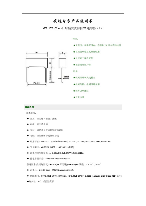
Dimensions: (mm)±0.5mm
Type: MPX-mini Dimensions: (mm)±0.5mm
可依客户要求,制作特殊规格。
波赫-赫格隆产品样本

可靠的、优质的产品带给您更高的效益
工作原理
成套直接驱动系统
成套直接驱动系统 是如何工作的
上海波赫驱动系统有限公司成套液压驱动系统无需变速箱, 内含各种液压马达、附件、动力站和控制系统。
驱动的速度是由液压泵的流量决定,因此可以轻松地控制功率、速度和扭矩。 这种液压闭式回路系统可以提供强劲的四象限驱动,可在正转或反转时驱动或制动。
在半排量情况下
单位扭矩 额定转速 最大转速 (Nm/bar) (rev/min)** (rev/min)
25
200
280
25
225
320
30
195
275
35
180
240
40 50
50 60 70 80 90 105
220 190
205 180 170 105 100 85
310 270
275 245 220 150 135 115
速比
1:2 1:2 1:2 1:2
1:2 1:2 1:2 1:2 1:2 1:2 1:2 1:2
尺寸.用花键联接的马达
马达型号 A(mm) B(mm)
CA50 CA70 CA100 CA140 CA210
464 495 560 600 600
312.5 312.5 399.5 399.5
501
C(mm)
390 435 470 510 510
D(mm)
46.5 46.5 135.5 135 156.5
E(mm)
N120x5 x30 x22 x9H N120x5 x30 x22 x9H N140x5 x30 x26 x9H N140x5 x30 x26 x9H N150x5 x30 x28 x9H
Lincoln Power TIG 275 焊接机说明书

ProcessesStick, TIGProduct NumberK2619-1K2619-2K2620-1K2618-1 Ready-Pak®Package See back for complete specs© Lincoln Global, Inc. All Rights Reserved.275TIG WELDERSInput Power (Voltage/Phase/Hertz)K2619-1/K2618-1:208/230/460/1/60K2619-2:460/575/1/60K2620-1:220-230/380-400/415/1/50/60Input Current at Rated Output208V:104460V:47220-230V:95575V:38230V:94380-400V:55415V:50Rated Output: Current/Voltage/Duty Cycle275A/31V/40%Weight/Dimensions (H x W x D)397 lbs. (180 kg)31 x 22 x 26 in.(787 x 559 x 660 mm)INPUT OUTPUTK2618-1 Includes:K2619-1Under-Cooler Cart Water Cooler –PH: +1.216-481-8100 • LI NC OL N E L E C TR ICShown K2619-1[ 2]|Precision TIG ®275What Is It?Pulse welding systems vary weld current between peak (high heat) and background current (low heat) levels. Adjusting the pulse frequency controls the level of heat input applied to the weld relative to the weld travel speed.ResultsBetter control of heat input in the weld, resulting in:•Reduced warping and burnthrough on thin materials. •Smaller heat-affected zone – good for thin material.•Smaller bead profile without compromising proper penetration.Easy “Set It/See It” Operation:•Flashing indicator light lets you see the pulse rate before you strike an arc.W e l d i n g C u r r e ntTimePulsed TIG Weld (at 60 amps)Standard TIG Weld (at 60 amps) Smaller HeatAffected ZoneSmaller Bead ProfileMicro-Start ™II Technology aids arc stabilityTHROUGHOUT THE WELD CYCLE – even at the lowest amperage! Micro-Start ™II Technologycontrolled ramp down helps precisely fill the weld crater for quality results.Micro-Start ™II Technology minimizes high frequency and ‘hot starts’ to deliver soft arc starts without arc wandering for AC and DC welding. Arc PerformanceMicro-Start ™Stable, Focused Arc Precise Crater Fill“Set It/See It” Pulse Control — Make attractive and consistent welds!N O WIN C L U D ESf o r A L UM IN U MW E L D INGA CPrecision TIG ®275| [ 3]AC Auto Balance ®Controls —Automatically sets the optimal cleaning vs. penetration level for aluminum welding!What Is It?When aluminum welding, the positive (+) portion of the AC weldingamperage cleans the oxides from the aluminum surface. The negative (-)portion delivers more heat input, increasing penetration level.Patented AC Auto Balance ®automatically sets the ratio of cleaning action (+) versus penetration (-) based on amperage.Manual balance control provides the flexibility to customize the arc to your preference.Easy Operation:•Set it and forget it or override when you choose to customize the settings.More Cleaning (+)Less Cleaning (+)Less Penetration(-)More Penetration (-)W E L D I N G W E L D I N G TIMETIMEMaximum Cleaning SettingMaximum Penetration SettingAuto Balance Setting•Fan-As-Needed (F.A.N.)™minimizes repeated heating and cooling of internal components, keeps dust and dirt build-up to a minimum and saves on electricity costs. •Engineered cooling air routing brings clean air in from the top and exhausts at the bottom to draw and collect less dirt in the machine. •Compare these reliability enhancing design features: — Crimped and soldered power connections.— Wound and varnished electrical coils do not require coil spacers used on competitive models. — Locking tabs on PC board connectors eliminates loose connections.•Tough testing cycles ensure long service — dropping, jerking,rolling, shipping, vibration, resistance to real world extreme conditions, and extended in-service life testing. •CSA C/US certified.•Lincoln three-year warranty on parts and labor.Clean, cool air route shown.Snap-action durable switches make positive mechanical contact to reduce chances ofintermittent contact failure.[ 4]| Precision TIG ®275Shown: K2618-1Water-Cooled Ready-Pak ®PackageTorch Parts Storage Compartment.Optional TIG pulsing helps you make great welds.Water-cooled torch connections with no adapters — side mounted to keep out of the way and protected.Neat/organized cable management with integratedtorch holster.Separate output studs for stick and TIG keep both stick electrode holder and TIG torch connected at the same time — eliminates set-up changeover when switching processes.Easily accessible input voltagereconnect panel.Low-Lift ™ Shielding Gas Bottle Platform.Lockable Undercarriage Storage and Water Cooler Drawers.Reliable Pro-Con Pump.Optional Features:(standard with K2618-1 Water-Cooled Ready-Pak ®Package)Precision TIG ®275| [ 5]Large, well-spaced controls make it easy to view and set upwith gloved hands.SET-UP MENUPress and hold the menu button to display up to seven programmable parameters. The setting of the desired level is displayed, and increasing or decreasing the level setting is easy.The Set-Up Menu includes:Standard•DC TIG Start Modes: High Frequency, Scratch Start, and Touch Start TIG ®.•Adjustable Preflow Time.•Adjustable Start Pulse for Soft or Forceful Starts.With Optional Advanced Control Panel •Adjustable TIG Hot Start.•Adjustable Upslope Time.•Adjustable Stick Hot Start.•Adjustable Stick Arc Force.A)Minimum Output Control & Display Switch (Also displays output voltage)B)Set-Up Menu (see below)C)Digital MeterD)Local/Remote Current Control Switch E)Maximum Output Control F)Post Flow Time G)Thermal Shutdown Light H)Optional Advanced Control Panel 1)Trigger Switch (2-step/4-step)2)Pulse/Spot Time Mode Switch 3)Pulse Frequency Control 4)Pulse % On Time Control 5)Pulse Background Current Control 6)Downslope Time, In Seconds 7)Spot Time I)Polarity Switch J)Power Switch K)AC Balance Control L)Mode SwitchH123 4 & 756BCDEAF G HI J KLC U S T O M E R A S S I S T A N C E P O L I C YThe business of The Lincoln Electric Company ®is manufacturing and selling high quality welding equipment, consumables, and cutting equipment. Our challenge is to meet the needs of our customers and to exceed their expectations. On occasion, purchasers may ask Lincoln Electric for information or advice about their use of our products. Our employees respond to inquiries to the best of their ability based on information provided to them by the customers and the knowledge they may have concerning the application. Our employees, however, are not in a position to verify the information provided or to evaluate the engineering requirements for the particular weldment. Accordingly, Lincoln Electric does not warrant or guarantee or assume any liability with respect to such information or advice. Moreover, the provision of such information or advice does not create, expand, or alter any warranty on our products. Any express or implied warranty that might arise from the information or advice, including any implied warranty of merchantability or any warranty of fitness for any customers’ particular purpose is specifically disclaimed.Lincoln Electric is a responsive manufacturer, but the selection and use of specific products sold by Lincoln Electric is solely within the control of, and remains the sole responsibility of the customer. Many variables beyond the control of Lincoln Electric affect the results obtained in applying these types of fabrication methods and service requirements.Subject to Change – This information is accurate to the best of our knowledge at the time of printing. Please refer to for any updated information.For best welding results with Lincoln Electric equipment,always use Lincoln Electric consumables. Visit for more details.GENERAL OPTIONSAdvanced Control Panel Provides 2/4-step trigger with adjustable Pulser controls and Downslope timer for TIG welding.Also includes adjustable Hot Start and Arc Force internal panel controls for stick welding, and other user selectable features.Order K2621-1Under-Cooler Cart Water Cooler Includes “cooler-in-a-drawer” with hoses and a lockable storage drawer on a dual bottle undercarriage. Two gallon (7.5 ltrs.) capacity.Order K1828-1UndercarriageIncludes a dual bottle rack with chain and front casters, rear wheels and a handle. Order K1869-1Harris ®Argon Flowmeter RegulatorDeluxe flowmeter/regulator. Includes 10 ft. (3.0 m) hose. Order 3100211Work Clamp & Cable Assembly 15 ft. 2/0 cable with 1/2 in. stud lug and work clamp. Order K2150-1STICK OPTIONSAccessory KitFor stick welding. Includes 35 ft.(10.7 m) 2/0 electrode cable with lug, 30 ft. (9.1 m) 2/0 work cable with lugs, headshield, filter plate,work clamp and electrode holder.400 amp capacity.Order K704Accessory KitFor stick welding. Includes 20 ft. (6.1 m) #6 electrode cable with lug,15 ft. (4.6 m) #6 work cable with lugs, headshield, filter plate, work clamp, electrode holder and sample pack of mild steel electrode. 150amp capacity.Order K875Remote Output ControlConsists of a control box with choice of two cable lengths. Permits remote adjustment of output. 6 pin connection.Order K857for 25 ft. (7.6 m)Order K857-1for 100 ft. (30.5 m) TIG OPTIONSMagnum®Pro-Torch™TIG TorchesA full line of air-cooled and water-cooled torches available.Request publication E12.150PTA-26 One-Cable AdapterAdapts the 7/8 in. PTA-26 fitting tothe 5/8 in. gas and powerconnection on machine. Order K2166-1PTA-9, -17 One-Cable Adapter Adapts the 3/8 in. PTA-9 or -17fitting to the 5/8 in. gas and power connection on machine.Order K2166-3PTA-9, PTA-17, PTA-26 Two-Cable AdapterConverts the 7/8 in. water andpower connection on the machine to a 1/2 in. output stud for use with a two-cable air-cooled TIG torch.Order K2166-2Foot Amptrol ™Varies current for making critical TIG welds. Depress pedal to increase current. Depressing pedal fullyachieves maximum set current. Fully raising the pedal finishes the weld and starts the afterflow cycle.Includes 25 ft. (7.6 m) control cable.6-pin plug connection.Order K870Hand Amptrol ™Provides 25 ft. (7.6 m) of remote current control for TIG welding (6 pin plug connection). Velcro straps secure torch.Order K963-3(One size fits all Pro-Torch ™TIG Torches.)Arc Start SwitchNeeded if an Amptrol ™is not used when TIG welding. Comes with a 25ft. (7.6 m) cable. Attaches to the TIG torch for convenient finger control. 6-pin plug connection. Order K814Cut Length Consumables TIG welding filler metals are available for welding stainless steel, mild steel, aluminum and copper alloys.See publication C1.10。
朋克公司的Hi-Pro系列球值和HNV系列喉管值的产品介绍说明书
Fast, repeatable, and reliable valve assemblies by torqueParker’s Hi-Pro Series ball valves and HNV Series needle valves feature an integral O-LOK ® O-Ring Face Seal (ORFS) fitting connections. These are suitable for high vibration and impulse applications up to 10,000 psi (689 bar). Parker’s O-LOK ® technology presents an optimal solution for mass production in the automotive industry, among others. Assembly by torque eliminates uncertainty regarding connection tightness. The face seal connections also simplify maintenance in confined spaces. They can be assembled and disassembled multiple times without compromising the connection’s integrity, making it easy to replace valves.Valves with O-LOK ®Ends for Hydrogen ServiceIntegral ended ball and needle valves for improved safety and leak-free operation in hydrogen applicationsContact Information:Parker Hannifin Manufacturing Ltd.Instrumentation Products Division Europe Riverside RoadBarnstaple EX31 1NP United Kingdomphone +44 (0) 1271 313131/ipdBenefitsTechnical InformationInstallation & OperationO-LOK ® installation and operationScan the QR code to view the Tube Assembly Guide (page 55).Or click here to view the Guide.Ball Valve Hi-Pro SeriesScan the QR code to view the Installation and Operation Manual on our mobile device.Or click here to view the Manual.Needle Valve HNV SeriesScan the QR code to view the Installation and Operation Manual on your mobile device.Or click here to view the Manual.O-LOK Valves 10/2023© 2023 Parker Hannifin CorporationParker Hannifin Manufacturing Ltd.Instrumentation Products DivisionEuropeRiverside RoadBarnstaple EX31 1NPUnited Kingdomphone +44 (0) 1271 313131/ipd。
Omega HE-XL102 数字 模拟输入 输出控制器说明书
e-mail:**************For latest product manuals:User’sGuideShop online atHE-XL10212 Digital DC Inputs, 4 Analog Inputs (Medium Resolution),6 Digital Relay OutputsIt is the policy of OMEGA Engineering, Inc. to comply with all worldwide safety and EMC/EMI regulations that apply. OMEGA is constantly pursuing certification of its products to the European New Approach Directives. OMEGA will add the CE mark to every appropriate device upon certification.The information contained in this document is believed to be correct, but OMEGA accepts no liability for any1 SpecificationsSpecifications Digital DC InputsInputs per Module12 including 4 configurableHSC inputsCommons per Module 1 Input Voltage Range 12 VDC / 24 VDC Absolute Max. Voltage 35 VDC Max. Input Impedance 10 k ΩΩΩInput Current Positive LogicNegative LogicUpper Threshold 0.8 mA -1.6 mA Lower Threshold0.3 mA-2.1 mA Max Upper Threshold 8 VDC Min Lower Threshold 3 VDCOFF to ON Response 1 ms ON to OFF Response1 msHSC Max. Switching Rate10 kHz Totalizer/Pulse,Edges5 kHz Frequency/Pulse, Width2.5 kHz QuadratureDigital Relay OutputsOutputs per Module 6 relay Commons per Module 6 Max. Output Current per Relay 3 A at 250 VAC, resistive Max. Total Output Current 5 A continuous Max. Output Voltage 275 VAC , 30 VDC Max. Switched Power 1250 VA, 150 W Contact Isolation to XL6ground1000 VACMax. Voltage Drop at RatedCurrent 0.5 VExpected Life(See Derating section forchart.)No load: 5,000,000Rated load: 100,000Max. Switching Rate300 CPM at no load20 CPM at rated loadType Mechanical ContactResponse TimeOne update per ladder scanplus 10 msAnalog Inputs, Medium Resolution4s l e n n a h C f o r e b m u N Input Ranges 0 - 10 VDC0 – 20 mA4 – 20 mASafe input voltage range -0.5 V to +12VInput Impedance(*******************VDC) Current Mode:100 Voltage Mode:500 k s t i B 01n o i t u l o s e R l a n i m o N s t n u o c 000,23e l a c s l l u f I A %Am 53t n e r r u C -r e v O .x a M Conversion SpeedAll channels converted onceper ladder scanMax. Error at 25°C(excluding zero)*can be made tighter (~0.25%)by adjusting the digital filtersetting to 3.4-20 mA 1.00% 0-20 mA 1.00% 0-10 VDC 1.50%* Additional error fortemperatures other than 25°CTBDFiltering 160 Hz hash (noise) filter1-128 scan digital runningaverage filterGeneral SpecificationsRequired Power (Steady State) 500 mA @ 24 VDCRequired Power (Inrush)30 A for 1 ms @ 24 VDC – DC Switched 2.5 A for 4 ms @ 24 VDC - AC SwitchedPrimary Power Range10 – 30 VDCg n i s n e d n o c -n o N %59o t 5y t i d i m u H e v i t a l e R Clock Accuracy +/- 35 ppm maximum at 25° C (+/- 1.53 Minutes per Month)Operating Temperature -10°C to +60°Cel b a v o m e R m m 5,e p y T w e r c S e p y T l a n i m r e T Weight 26.5 oz. (.751 kg)CE ULHE-XL102If you require a Compliance Table: 1-888-556-63422 Installation1. Prior to mounting, observe requirements for the panel layoutdesign and spacing/clearances in the OCS XL6 Series Manual (MAN0883).2. Cut the host panel.3. Insert the OCS through the panel cutout (from the front). Thegasket material needs to be between the host panel and theOCS.4. Install and tighten the mounting clips (provided with the OCS) untilthe gasket material forms a tight seal.5. Connect cables as needed such as communications,programming, power and CsCAN cables to the ports using theprovided connectors.6. Begin configuration procedures. 3 Panel Cut-Out and Dimensions4Ports and ConnectorsExternal DIP Switch SettingsAs seen when looking at the side of the XL6 unit :MJ1MJ2OnOff On Off On OffCAN ConnectorUse the CAN Connector when using CsCAN network.CAN Network Port and Wiring4.45 Wiring and Jumpers5.1 I/O Jumpers Settings (JP1 - JP2) 5.2 Wiring Examples6 FilterFilter Constant sets the level of digital filtering according to the following chart.Digital Filtering . The illustration above demonstrates the effect of digital filtering (set with Filter Constant)on module response to a temperature change.602010040802001010090807060504030Scans12345607%C o m p l e t e Filter ConstantNote:The Cscape Module Setup configuration must match theselected I/O (JP) jumper settings.JP1 Digital DC In / HSC Positive Negative Logic LogictDefaultA1A2 A3 A4JP2 Analog In (A1 – A4) Current Voltage (20 mA) (10 V)DefaultNote:When using JP2 (A1-A4), e ach channel can be independentlyconfigured.7 Derating 8 I/O Register Map9 SafetyRegisters Description%I1 to %I24Digital Inputs %I32Output Fault %I25 to %I31 Reserved %Q1 to %Q16Digital outputs%Q17Clear HSC1 accumulator to 0%Q18 Totalizer: Clear HSC2Quadrature 1-2: Accumulator 1Reset to max – 1%Q19 Clear HSC3 Accumulator to 0%Q20 Totalizer: Clear HSC4Quadrature 3-4: Accumulator 3Reset to max – 1%Q21 to %Q32 Reserved %AI1 to %AI4 Analog inputs %AI5, %AI6 HSC1 Accumulator %AI7, %AI8 HSC2 Accumulator %AI9, %AI10 HSC3 Accumulator %AI11, %AI12HSC4 Accumulator%AQ1, %AQ2PWM1 Duty Cycle %AQ3, %AQ4 PWM2 Duty Cycle %AQ5, %AQ6 PWM Prescale %AQ7, %AQ8 PWM Period %AQ9 to %AQ14 Analog outputsNote: Not all XL6 units contain the I/O listed in this table.• All applicable codes and standards need to be followed in the installation of this product.• Adhere to the following safety precautions whenever any type of connection is made to the module: • Connect the safety (earth) ground on the power connector first before making any other connections. • When connecting to electric circuits or pulse-initiating equipment, open their related breakers. • Do not make connections to live power lines.• Make connections to the module first; then connect to the circuit to be monitored.• Route power wires in a safe manner in accordance with good practice and local codes.•Wear proper personal protective equipment including safety glasses and insulated gloves when making connections to power circuits.• Ensure hands, shoes, and floors are dry before making any connection to a power line. • Make sure the unit is turned OFF before making connection to terminals. • Make sure all circuits are de-energized before making connections.•Before each use, inspect all cables for breaks or cracks in the insulation. Replace immediately if defective.• Use Copper Conductors in Field Wiring Only, 60/75° CThis device complies with part 15 of the FCC Rules. Operation is subject to the following two conditions: 1. This device may not cause harmful interference.2. This device must accept any interference received, including interference that may cause undesiredoperation. Radiated Emission Compliance : For compliance requirement, a ferrite (Horner P/N FBD006 supplied with the unit) needs to be placed on the AC/DC line with one loop.When found on the product, the following symbols specify:WARRANTY/DISCLAIMEROMEGA ENGINEERING, INC. warrants this unit to be free of defects in materials and workmanship for a period of 13 months from date of purchase. OMEGA’s WARRANTY adds an additional one (1) month grace period to the normal one (1) year product warranty to cover handling and shipping time. This ensures that OMEGA’s customers receive maximum coverage on each product.If the unit malfunctions, it must be returned to the factory for evaluation. OMEGA’s Customer Service Department will issue an Authorized Return (AR) number immediately upon phone or written request.Upon examination by OMEGA, if the unit is found to be defective, it will be repaired or replaced at no charge. OMEGA’s WARRANTY does not apply to defects resulting from any action of the purchaser,including but not limited to mishandling, improper interfacing, operation outside of design limits, improper repair, or unauthorized modification. T his WARRANT Y is VOID if the unit shows evidence of having been tampered with or shows evidence of having been damaged as a result of excessive corrosion;or current, heat, moisture or vibration; improper specification; misapplication; misuse or other operating conditions outside of OMEGA’s control. Components in which wear is not warranted, include but are not limited to contact points, fuses, and triacs.OMEGA is pleased to offer suggestions on the use of its various products. However, OMEGA neither assumes responsibility for any omissions or errors nor assumes liability for any damages that result from the use of its products in accordance with information provided by OMEGA, either verbal or written. OMEGA warrants only that the parts manufactured by it will be as specified and free of defects. OMEGA MAKES NO OTHER W ARRANTIES OR REPRESENTATIONS OF ANY KIND WHATSOEVER, EXPRESS OR IMPLIED, EXCEPT THAT OF TITLE,AND ALL IMPLIED WARRANTIES INCLUDING ANY WARRANTY OF MERCHANTABILITY AND FITNESS FOR A PARTICULAR PURPOSE ARE HEREBY DISCLAIMED. LIMITATION OF LIABILITY: The remedies of purchaser set forth herein are exclusive, and the total liability of OMEGA with respect to this order, whether based on contract, warranty, negligence, indemnification, strict liability or otherwise, shall not exceed the purchase price of the component upon which liability is based. In no event shall OMEGA be liable for consequential, incidental or special damages.CONDITIONS: Equipment sold by OMEGA is not intended to be used, nor shall it be used: (1) as a “Basic Component” under 10 CFR 21 (NRC), used in or with any nuclear installation or activity; or (2) in medical applications or used on humans. Should any Product(s) be used in or with any nuclear installation or activity, medical application, used on humans, or misused in any way, OMEGA assumes no responsibility as set forth in our basic WARRANTY/ DISCLAIMER language, and, additionally, purchaser will indemnify OMEGA and hold OMEGA harmless from any liability or damage whatsoever arising out of the use of the Product(s) in such a manner.RETURN REQUESTS/INQUIRIESDirect all warranty and repair requests/inquiries to the OMEGA Customer Service Department. BEFORE RET URNING ANY PRODUCT (S) T O OMEGA, PURCHASER MUST OBTAIN AN AUT HORIZED RET URN (AR) NUMBER FROM OMEGA’S CUST OMER SERVICE DEPART MENT (IN ORDER T O AVOID PROCESSING DELAYS). The assigned AR number should then be marked on the outside of the return package and on any correspondence.The purchaser is responsible for shipping charges, freight, insurance and proper packaging to prevent breakage in transit.FOR WARRANTY RETURNS, please have the following information available BEFORE contacting OMEGA:1.Purchase Order number under which the product was PURCHASED,2.Model and serial number of the product under warranty, and3.Repair instructions and/or specific problems relative to the product.FOR NON-WARRANTY REPAIRS,consult OMEGA for current repair charges. Have the followinginformation available BEFORE contacting OMEGA:1. Purchase Order number to cover the COST of the repair,2.Model and serial number of the product, and3.Repair instructions and/or specific problems relative to the product.OMEGA’s policy is to make running changes, not model changes, whenever an improvement is possible. This affords our customers the latest in technology and engineering.OMEGA is a registered trademark of OMEGA ENGINEERING, INC.© Copyright 2009 OMEGA ENGINEERING, INC. All rights reserved. T his document may not be copied, photocopied,Where Do I Find Everything I Need for Process Measurement and Control?OMEGA…Of Course!Shop online at smTEMPERATUREⅪߜThermocouple, RTD & Thermistor Probes, Connectors, Panels & AssembliesⅪߜWire: Thermocouple, RTD & ThermistorⅪߜCalibrators & Ice Point ReferencesⅪߜRecorders, Controllers & Process MonitorsⅪߜInfrared PyrometersPRESSURE, STRAIN AND FORCEⅪߜTransducers & Strain GagesⅪߜLoad Cells & Pressure GagesⅪߜDisplacement TransducersⅪߜInstrumentation & AccessoriesFLOW/LEVELⅪߜRotameters, Gas Mass Flowmeters & Flow ComputersⅪߜAir Velocity IndicatorsⅪߜTurbine/Paddlewheel SystemsⅪߜTotalizers & Batch ControllerspH/CONDUCTIVITYⅪߜpH Electrodes, Testers & AccessoriesⅪߜBenchtop/Laboratory MetersⅪߜControllers, Calibrators, Simulators & PumpsⅪߜIndustrial pH & Conductivity EquipmentDATA ACQUISITIONⅪߜData Acquisition & Engineering SoftwareⅪߜCommunications-Based Acquisition SystemsⅪߜPlug-in Cards for Apple, IBM & CompatiblesⅪߜDatalogging SystemsⅪߜRecorders, Printers & PlottersHEATERSⅪߜHeating CableⅪߜCartridge & Strip HeatersⅪߜImmersion & Band HeatersⅪߜFlexible HeatersⅪߜLaboratory HeatersENVIRONMENTALMONITORING AND CONTROLⅪߜMetering & Control InstrumentationⅪߜRefractometersⅪߜPumps & TubingⅪߜAir, Soil & Water MonitorsⅪߜIndustrial Water & Wastewater TreatmentⅪߜpH, Conductivity & Dissolved Oxygen Instruments。
凯朔达 PCS 恒温扑控 ком合气体传感器说明书
PCS C OMBINATION S ENSOR WITH D ISPLAY75 Discovery Way•Acton, MA 01720 USA •Tel (978) 795-1285•Fax (978) 795-1111•©2020 Phoenix Controls. Specifications subject to change without notice. Rev. 04/2021 MKT-0442MPC-2606PCS C OMBINATION S ENSOR WITH D ISPLAY1Phoenix Controls temperature sensors provide a stable and secure environment for those facilities that need it the most, such as hospitals, cleanrooms, and laboratory animal facilities. The sensors also simplify room balancing by eliminating the need for a certified person to accompany the balancer during the commissioning process.The PCS4xx/5xx/6xx series, microprocessor-based sensor, provides a choice of three temperature sensor output signal signals and three humidity sensor output signals. The five pushbuttons allow easy adjustment of set points, occupancy override, and access to the setup menu. The large backlit LCD display allows simultaneous display of two values (temperature, temperature set point, humidity, or humidity set point) and occupancy status.Features •Test and Balance in the setup menu for heating, cooling, and normal operation •Fully configurable set point range, relative or absolute•Large Backlit LCD Display with readings within a tenth of a degree •Simultaneous display of temperature, humidity, and occupancy status •3.5 mm communications jack (standard)•Foam backing for drywall or 2" x 4" single gang junction box mounting (standard)•Optional 3 Point NIST Calibration CertificatesSPECIFICATIONSSpecificationTemperatureHumidity4xx Series5xx Series6xx Seriesx05/x10/x20 SeriesSensor Output Range (Span)32-122 °F (0-50 °C)40-104 °F (5-40 °C)32-122 °F (0-50 °C)0-100%Sensing Element Thermistor (NTC)Platinum RTD (PTC)Thermistor (NTC)Impedance T ype Humidity Sensor Signal, Sensor Output(Common Ground)10 K Type 2 thermistor 0-10 Vdc20K NTC0 to 5 Vdc, or 0 to 10 Vdc, or 4 to 20 mAKeypadConfiguration 5 Pushbuttons (Setup, Up and Down Arrows, O/R (Occupancy Override), and Select)Signal, Set Point Output(Common Ground)0-20K ohms0-10 Vdc9.5-1K ohms0 to 5 Vdc, or 0 to 10 Vdc, or 4 to 20 mALocal Occupancy Control Contact closure to common groundDisplay Blue backlight LCD, 2.27”x 1.7”, 3 LED, programming option for 0 or 1 decimal point Display Unit of MeasurePush Button Programming (°F (standard) or °C)Setpoint Display and Range(Push Button Control & Programming)Fully configurable via pushbutton menu:- Setpoint range: 55 to 89 °F (15 to 31 °C)- Setpoint Adjust: adjustable up to -20 to +20 °F or °C of setpoint (1 °F or0.5 °C increments)- Setpoint Limits: 40 to 104 °F (4.5 to 40 °C)- Relative range: up to -20 to 20 ° F or °C (1 °F or 0.5 °C increments)Fully configurable via pushbutton menu:- Setpoint range: 33 to 67%- Setpoint Adjust: adjustable up to -20% to +20% of setpoint (1% increments)- Setpoint Limits: 13% to 87%Occupancy Display Remote contact closure to common ground indicates Occupied on display Housing Material/ColorABS/PC (White); UL 94-5VBPCS Combination Sensor2 PCS C OMBINATION S ENSOR WITH D ISPLAY MKT-0442 MPC-2606 ©2020 Phoenix Controls. Specifications subject to change without notice. Rev. 04/2021DIMENSIONSTest & BalanceSettings(Push Button Control) 40 °F (4.4 °C), 72 °F (22.2 °C), and 104 °F (40 °C)0%, 50%, and 100%Communication Jack 3.5 mm Stereo Jack (Ring, Tip, Shield)Operating Range 35-122 °F (1.5-50 °C), 0-95% Relative Humidity Non-Condensing Storage Range -4-131 °F (-20-60 °C), 0-95% Relative Humidity Non-Condensing Reference Resistance 10K ohm @ 77 °F (25 °C)1K ohm @ 32 °F (0 °C)20K ohm @ 77 °F (25 °C)N/AAccuracySensor Output Accuracy: +/- 1.0 °F (+/- 0.56 °C): LCD Display Accuracy +/- 1.5 °F due to Rounding2% from 10 to 95% RH @ 77 °F (25 °C)Dissipation Constant N/AResponse Time 10 seconds nominal for a 63% step increase (room-hot water)11 seconds nominal for a 63% step decrease (room-ice water)20 seconds for a step of 46%-96%45 seconds for a step of 98%-47%Stability < 1% after 1000 hours at 212 °F (100 °C)N/A< 1% after 1000 hours at 212 °F (100 °C)< 2% over 5 years Supply Voltage +18 to 40 Vdc (NOTE: Use of PVC400-HW is required for LON applications)Power Consumption < 0.65 VA (x05 and x10 Series), < 4 VA (x20 Series)Product Dimensions (L x W x D) 4.56" (115.82 mm) x 3.0" (76.2 mm) x 1.45" (36.75 mm)Product Weight 0.35 lbs (0.162 kg)NIST Certification (6 Points)61 °F (16 °C), 72 °F (22.5 °C), and 82 °F (28 °C)20%, 50%, and 80% @ 72 °F (22 °C)Regulatory ComplianceSpecificationTemperatureHumidity4xx Series5xx Series6xx Seriesx05/x10/x20 SeriesWEEE Directive 2012/19/ECWaste Electrical and Electronic Equipment directiveAt the end of the product life dispose of the packaging and product in a corresponding recycling centre. Do not dispose of the unit with the usual domestic refuse. Do not burn the product.EU Contact Address:Pittway Tecnologica Srl Via Caboto 19/334147 Trieste TS Italy©2020 Phoenix Controls. Specifications subject to change without notice. Rev. 04/2021 MKT-0442 MPC-2606PCS C OMBINATION S ENSOR WITH D ISPLAY 3ORDERING GUIDEValid Catalog NumbersOUTPUT FORMULAS AND TABLESFor output formulas and complete sensor output tables, see MKT-0474 Sensor Outputs and T ables .PHX-COMBINATION-SENSOR (10K-2 Temperature Output)PHX-COMBINATION-SENSOR (0-10VDC Temperature Output)PHX-COMBINATION-SENSOR (20KTemperature Output)Catalog Number without CalibrationCertificate Catalog Number with 6 Point CalibrationCertificate Catalog Number without CalibrationCertificate Catalog Number with 6 Point CalibrationCertificate Catalog Number without CalibrationCertificate Catalog Number with 6 Point CalibrationCertificate PCS405-R-DOP PCS405-R-DOP-06PCS505-R-DOP PCS505-R-DOP-06PCS605-R-DOP PCS605-R-DOP-06PCS405-R-DHOP PCS405-R-DHOP-06PCS505-R-DHOP PCS505-R-DHOP-06PCS605-R-DHOP PCS605-R-DHOP-06PCS410-R-DOP PCS410-R-DOP-06PCS510-R-DOP PCS510-R-DOP-06PCS610-R-DOP PCS610-R-DOP-06PCS410-R-DHOP PCS410-R-DHOP-06PCS510-R-DHOP PCS510-R-DHOP-06PCS610-R-DHOP PCS610-R-DHOP-06PCS420-R-DOP PCS420-R-DOP-06PCS520-R-DOP PCS520-R-DOP-06PCS620-R-DOP PCS620-R-DOP-06PCS420-R-DHOPPCS420-R-DHOP-06PCS520-R-DHOPPCS520-R-DHOP-06PCS620-R-DHOPPCS620-R-DHOP-06。
MPX 275VAC承认书
12
Dry Heat Resistance
Insulation Resistance 量 率 Capacitance Variation
Temperature: +100 Duration: 96 4 hrs
2°C
Appearance
Withstand Voltage
13
Humidity Resistance
5 6
量 Capacitance 數 Dissipation Factor 拉 度 Pull Strength
Within specified tolerance 0.1 %max at 1KHz
7
度 Terminal Strength
不 No cutting or slack of terminals 度 Bending Strength 異 No abnormality of the appearance 95% At least 95% of the surface of the lead wire dipped into is covered with new solder. 異 No abnormality on appearance 3 Comply with item 3 3%
Charge time: 60 5sec. Charge voltage: 100VDC Test Temp: 25°C at 1 KHz 10% Measure R.V: 5 Vrms or below Test temp: 25°C Measure R.V: 5 Vrms or below Test temp: 25°C Wire diameter: 0.6&0.8 mm Load: 1 kg, time: 10 sec. Wire diameter: 1.0 mm Load: 2 kg, time: 20 sec. Wire diameter: 0.6&0.8 mm Load: 0.5 kg, 90° x 4 time Wire diameter: 1.0 mm Load: 1 kg, 90° x 4 time Frequency range 10-55-10 Hz Amplitude: 1.5 mm, 2 hrs/direction for 3 directions Solder temp: 240 2°C Immersion time: 2 0.5sec. Solder: SnAgCu (Sn:96.5% Ag:3% Cu:0.5%)
- 1、下载文档前请自行甄别文档内容的完整性,平台不提供额外的编辑、内容补充、找答案等附加服务。
- 2、"仅部分预览"的文档,不可在线预览部分如存在完整性等问题,可反馈申请退款(可完整预览的文档不适用该条件!)。
- 3、如文档侵犯您的权益,请联系客服反馈,我们会尽快为您处理(人工客服工作时间:9:00-18:30)。
Rated Voltage 额定电压
'
HEL's P/N料号: MPX104K7BA8A50R0
DRAWING & MARKING Outline Dimension 外型尺寸(mm) Width 宽度 18.0 Pitch 脚距 15.0
W +0.4/-07
Zin/Aluminium 锌/铝 50~60HZ 1KHZ 10KHZ 100KHZ
DC lead to lead DC lead to case AC lead to lead AC lead to case
Constructure 结构
Height 高度 12.0 dø 线径 0.7
T ±0.4
Remark: ①0.1uF:Normal Capacitance in uF
H±0.4 ②K:Capacitance tolerance (J:±5% K:± 10% M:±20%) ③MPX:Type of row material ④HEL:The trade mark of Hongzhi ⑤275V~310V~:AC rated voltage ⑥UL.CSA.VDE.CQC :Safetyapproval marks
HEL
@25℃ 50HZ 275VAC Winding 卷绕
Protection/Coating PBT Plastic Box 阻燃塑胶盒UL94 V-0 外封装 Resin filled 灌封 Lead Wire 导线 Colour 本体颜色 Flame retardant epoxy 阻燃环氧树酯UL94 V-0 CP Wire 镀锡铜包钢线 Yellow 浅黄色
0.1uF
Dielectric Withstanding Voltage Between terminals 250
介质耐压强度
VDCx7.0 1sec max
20°C@100 VDC 60 seconds Lead to lead Insulation Resistance min 20°C@………VDC……… 绝缘阻抗 Lead to case seconds min dv/dt max Max pulse rise time 单位时间电压变化率 IpeakA @70°C 最大值电流 IrmsA 实效值电流 Surge/Pulse voltage 抗冲击电压 E.S.R 等效串联阻抗值 @70°C …… % rated voltage max …………Ω Standard 引用标准 Climatic Category 气候类别 Sampling Standard 取样标准 Confirmation area : 客户承认签回区
L.L Min
≥ 15,000MΩ …………MΩ 200(v/μsec) 20.0Amps mAs …………VDC IEC 60384-14 -40℃ /+ 105℃ / 56 Days MIL-STD-105E-Ⅱ 容量C、 损耗角tgδ、 绝缘电阻IR 耐压(Ur) 外观&尺寸 AppeaDimen 可焊性 Sol 耐焊热性Sol
Thickness 厚度 6.0 LL 线长 15.0
………… 0.10% 0.15% ………… 1183 VDC …………VDC …………VAC 2050 VAC 1750 VDC
Test Voltage 测试电压
4.3times of rated voltage for 5seconds max cut off current at 10mA
P±0.5
dΦ±0.05 Inspection Level检验标准 IL检验标准 AQL允收标准
Inspection Item 检查项目
1.0Vrms,1KHZ, 20±3℃ 符合规范要求 Ⅱ 4.3倍额定电压,5秒内无飞弧与击穿 无针孔、气泡、毛刺,标志清晰,尺寸无超出最大值 265-5/+0℃ 2.5±0.5秒 沾锡面积≥90% 2.5%l UL NO: E192572 VDE NO: 40023936 安全认证 CSA NO: 2052630 ENEC NO: NO2154 Remark: 备注
CQC NO :CQC07001018754
RoHS Compliant
S3 280±5℃/10±0.5秒 △C/C≤±2%, tanδ≤0.1%, IR≥ 15,000M Ω Designer : Operating Temperature: Design code: 设计 工作温度 设计代码 Mr.Liu MPX104K7BA8A50R0 -40℃ ~ +105 ℃ DATE发行日期 :Jun-13-2016 Drawing g: Appoval pp : Drawing g NO. 3RD ANGLE PROJECTION 绘图 核准 图号 第三角法 Ms.Zhang Mr.Lin HZ001 SCALE比例~ Unit单位:mm
Customer客户名称:
Capacitance 容量 Dielectric Polypropylene 聚丙烯膜 绝缘介质 Dissipation Factor 损耗角 @1KHZ 1Vrms 20°C max @1KHZ 20°C±3°C 0.1 μF
Customer s P/N客户料号: X2 104K275VAC P=15.0