
Alteon负载均衡配置说明十
Alteon负载均衡配置说明十
****Basic L4 LB Config
/cfg/slb/on 开启负载均衡功能
/cfg/slb/adv/direct en 为所有VI和服务启动DAM /c/slb/layer7/redir/urlal dis htt负载均衡不限请求类型
/c/slb/layer7/redir/nocache dis htt负载均衡不限cache类型
/cfg/slb/real 1/ri 192.168.54.1/en 添加real server1并enable
/cfg/slb/real 2/ri 192.168.54.2/en 添加real server2并enable
/cfg/slb/grou 60/add 1/add 2 将real server1/2添加到grou60 /cfg/slb/grou 60/health 3 grou60选择健康检查方式
/cfg/slb/virt 1/vi 10.0.0.173/en 添加vi1并enable
/cfg/slb/virt 1/service 1813/grou 60 为vi1添加service80并关联grou1 /cfg/slb/ort 5/client en 在与客户端连接的端口开启Client rocess
/cfg/slb/ort 6/client en 在与客户端连接的端口开启Client rocess
/cfg/slb/ort 7/server en 在与服务器端连接的端口开启Server rocess /cfg/slb/ort 8/server en 在与服务器端连接的端口开启Server rocess
***Filter 配置—htt流量负载均衡
/c/slb/filt 80
ena enable filter 80
action redir 处理方式为redir在指定grou内做负载均衡iver v4
si any 源
smask 0.0.0.0
di any 目的
dmask 0.0.0.0
roto tc 协议
grou 指定在grou 70(GW server)内做负载均衡rort 8080 real server 端口
vlan any filter应用vlan
alic htt 命中filter应用类型为htt
/c/slb/filt 80/adv
reverse dis
/c/slb/filt 80/adv/layer7
l7lku ena
/c/slb/filt 80/adv/redir
dbind ena 开启dbind delayed binding
rtroxy ena 将目的转换为real server I
iotions ena 在iotions中插入原始I及端口
****Filter 配置—非htt流量转发
/c/slb/filt 81
ena enable filter 81
action redir 处理方式为redir在指定grou内做负载均衡iver v4
si any 源
smask 0.0.0.0
di any 目的
dmask 0.0.0.0
roto tc 协议
grou 100 指定在grou 70(default GW)内做负载均衡rort 0 目的端口不转换
vlan any filter应用vlan
/c/slb/filt 81/adv/redir
dbind ena delayed binding
****FIlter 配置----10.0.0.172
/c/slb/filt 90
ena enable filter 90
action redir 处理方式为redir在指定grou内做负载均衡iver v4
si any 源
smask 0.0.0.0
di 10.0.0.172 目的
dmask 255.255.255.255
roto ud 协议
dort 9200 目
的端口
grou 20 指定在grou 20 (GW server)内做负载均衡rort 0 目的端口不转换
vlan any filter应用vlan
/c/slb/filt 90/adv/redir
rtroxy ena 将目的转换为real server I
***FIlter 关联端口
/c/slb/ort 5
client ena
filt ena
add 10
add 20
add 80-81
add 90-93
/c/slb/ort 6
client ena
filt ena
add 10
add 20
add 80-81
add 90-93
***Alteon config Dum "/cfg/dum"
>> Main# /cfg/d
scrit start "Alteon Alication Switch 4408" 4 /**** DO NOT EDIT THIS LINE!
/* Configuration dum taken 15:57:42 Fri Jan 21, 2011
/* Configuration last alied at 15:40:01 Fri Jan 21, 2011
/* Configuration last save at 15:57:36 Fri Jan 21, 2011
/* Version 27.0.0, Base MAC address 00:03:b2:50:f9:80 /cfg/l2/stg 1/off
/cfg/l3/if 1
ena
iver v4
addr 10.1.1.1
mask 255.255.255.0
broad 10.1.1.255
/cfg/slb
on
/cfg/slb/adv
direct ena
/cfg/slb/real 1
ena
iver v4
ri 10.1.1.101
-
/cfg/slb/real 2
ena
iver v4
ri 10.1.1.102
/cfg/slb/grou 1
iver v4
add 1
add 2
/cfg/slb/ort 1
client ena
/cfg/slb/ort 2
server ena
/cfg/slb/virt 1
ena
iver v4
vi 10.1.1.100
/cfg/slb/virt 1/service 80 htt
grou 1
/
scrit end /**** DO NOT EDIT THIS LINE!。
Alteon 实验操作手册
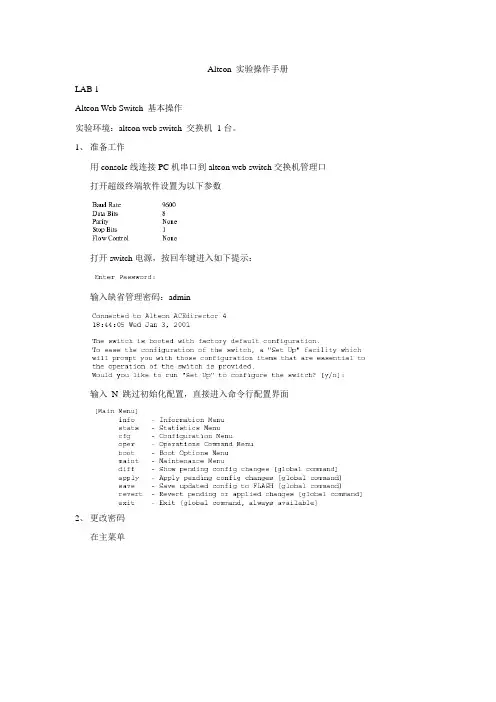
Alteon 实验操作手册LAB 1Alteon Web Switch 基本操作实验环境:alteon web switch 交换机1台。
1、准备工作用console线连接PC机串口到alteon web switch交换机管理口打开超级终端软件设置为以下参数打开switch电源,按回车键进入如下提示:输入缺省管理密码:admin输入N 跳过初始化配置,直接进入命令行配置界面2、更改密码在主菜单输入:Main#/cfg 进入配置菜单输入:>> Configuration#sys 进入系统菜单输入:System# user/admpw 更改系统密码Changing ADMINISTRATOR password; validation required... Enter current administrator password:输入当前密码Enter new administrator password:输入新密码Re-enter new administrator password:重复密码System# apply 应用配置System# save 保存配置3、配置VLAN,端口等L2信息。
创建VLAN进入配置菜单输入:>> Configuration#vlan (2-1024)进入vlan配置菜单>> vlan 2# ena (打开vlan 2)>> vlan 2# add 2 (把端口2加到 vlan 2)4、配置IP 接口地址、路由、网关等L3信息。
配置Interface 信息在配置菜单输入:>> Configuration#ip进入ip选项菜单输入:>> IP#if 1进入interface配置输入:>> IP Interface 1#addr 192.168.0.252>> IP Interface 1#mask 255.255.255.0>> IP Interface 1#ena>> IP Interface 1#..(返回IP配置菜单)配置路由信息输入:>> IP#route 进入路由配置>> IP Static Route#add (添加静态路由记录)>> IP Static Route#..(返回IP配置菜单)配置缺省网关输入:>> IP#gw 配置网关信息>> Default gateway 1#addr 192.168.0.254 (网关地址) >> Default gateway 1#ena>> Default gateway 1#apply>> Default gateway 1#save5、升级image系统软件、boot image 、bin文件。
北电Alteon应用层交换机技术手册_Insert mode cookie-based persistence

T e c h n i c a l T i pTT-0501402a -- Information -- 10-Jan-2005Insert mode cookie-based persistenceContents Contents (1)Introduction (1)Associated Products: (1)Overview (1)Nortel Web and Application switch cookie persistency (3)Insert cookie mode (3)Sample Configuration (4)Setup (4)Configuring the PC (4)Configuring WebServer1 (6)Configuring WebServer2 (7)Configuring Alteon (7)Configuring interfaces (7)Configuring real servers (8)Assigning real servers to a group (8)Configuring the virtual server (9)Enabling client/server processing on ports (10)Enabling direct access mode (10)Enabling SLB globally (10)Testing the configuration (11)Testing with expiration timer set (20)Appendix A. Alteon configuration file (23)Appendix B. Alteon configuration file with cookie expiration timer (24)IntroductionThis document illustrates the operation and sample configuration of insert mode cookie-based persistence in Nortel Web and Application switches (formerly known as Alteon Web and Application switches).Associated Products:The information in this document is intended to be used with the following product(s) with the indicated software or hardware revisions:Product Name or Order NumberRevision InformationPotentially Affected Corrected Nortel Web and Application switches (formerly known as Alteon Weband Application switches): 180e, 180 Plus, 184, AD2, AD3, AD4,All N/A 2224, 2424, 2208, 2216, 3408OverviewCookies are a mechanism used to create a stateful session with HTTP requests and responses. Prior to the introduction of the cookie concept, HTTP servers would respond to each client request without relating that request to subsequent requests. The concept of cookies allows clients and servers that wish to exchange state information to place HTTP requests and responses within a larger context, or a so-called session. This context could be used to maintain a state of the session that could be necessary for some web applications. For example, a stateful session could be used for e-commerce, when the state would reflect the client’s product selections or shopping cart. Or it could be used by web server administrators to count how many returning clients have visited the web site.Cookies are strings that are placed into the HTTP header and passed from the server to the client’s web browser. When the client initiates a connection to the server, it establishes a TCP session with a server and passes the HTTP request. A cookie-enabled server processes the HTTP request and sends the client an HTTP response containing an extra header: the Set-Cookie header. The Set-Cookie header contains:• a cookie name and its value•an optional comment•an optional domain name (always starts with a leading dot)•the optional max age of the cookie (if the max age is not specified in the Set-Cookie header, the user agent deletes the cookie as soon as the client closes the web browser)•an optional path that specifies the subset of URLs which a particular cookie applies to•an optional secure attribute that directs the user agent to use only a secure means to connect to the server • a version attribute that identifies the version of the state management specificationFor example, below is a Set-Cookie header sent by the HTTP server at :Set-Cookie: PREF=ID=4ae1d3ef46a57924:TM=1087567406:LM=1087567406:S=K62mTGGTRKDuigtw; expires=Sun, 17-Jan-2038 19:14:07 GMT; path=/; domain=\r\nOnce the client receives the cookie in the HTTP response, it stores it locally (unless configured to ignore cookies), usually in a form of a text file. Note that the location and form of storage depend on the web browser and operating system on a client’s PC. For example, the received cookie from could be stored as follows:Once the cookie is received (assuming the client’s web browser supports cookies), the client uses that cookie to send subsequent requests to the server. The cookie request header is used to send the cookie information back to the server. The cookie header contains the same attributes as the received Set-Cookie directive, with the exception of the comment, max age and secure attributes that are not sent back to the server.For example, below is a subsequent request to the :Hypertext Transfer ProtocolGET /images/logo.gif HTTP/1.1\r\nAccept: */*\r\nReferer: /\r\nAccept-Language: en-us\r\nAccept-Encoding: gzip, deflate\r\nUser-Agent: Mozilla/4.0 (compatible; MSIE 5.5; Windows NT 5.0; T312461; PC SRP2.0)\r\nHost: \r\nConnection: Keep-Alive\r\nCookie:PREF=ID=4ae1d3ef46a57924:TM=1087567406:LM=1087567406:S=K62mTGGTRKDuigtw\r\n \r\nThe server might ignore the received cookie or use it to determine the state of a session.Nortel Web and Application switch cookie persistencyNortel Web and Application switches support cookie-based persistency that allows the switch to redirect clients to the real server that initially processed the request. With cookie-based persistent load balancing, once an initial real server is selected based on the configured group metric, the switch forwards the subsequent requests based on the cookie header in the client’s HTTP request.Nortel Web and Application switches can operate in three modes of operation – insert cookie, passive cookie and rewrite cookie. This document illustrates the insert cookie mode. For information on passive or rewrite cookie modes, please consult the technical tips titled “Passive mode cookie-based persistence” or “Rewrite mode cookie-based persistence”.Insert cookie modeWhen operating in insert cookie mode, the switch inserts a cookie into the HTTP response on behalf of a real server, thus the real server does not need to have cookie server software installed on it.When the client sends an initial HTTP request with no cookies set in it, the switch performs load balancing and selects a real server based on the configured metric (Figure 1).The real server receives the request, processes it and sends an HTTP reply back to the client, no cookies are inserted by the real server as it was not configured to so.The switch receives an HTTP reply, calculates a cookie value, inserts it into the HTTP reply, and forwards the reply back to the client PC. If the client needs to make a subsequent request to the server, it inserts the cookie request header into HTTP request. When the switch receives an HTTP request containing its previously inserted cookie value, it looks up the real server associated with the cookie and forwards the request to the initially selected server.Client sends HTTP request/no cookiesSwitch forwards therequest to real server/nocookiesReal server respondswith HTTP reply/nocookiesSwitch inserts a cookie into server’s replyand forwards HTTP reply to Client PC/cookieinsertedClient uses the received cookie forsubsequent HTTP requests/cookie insertedSwitch forwards thesubsequent request tothe real server based onthe cookie informationFigure 1Sample ConfigurationSetup• PC – Windows 2000 professional with Microsoft Internet Explorer 5.5 installed, IP address 192.168.10.77/24 • Alteon – Nortel Web switch AD3, code version 10.0.30.7, interface 1 IP 192.168.10.100/24, interface 2 IP 192.168.20.200/24, Virtual IP 192.168.10.150, port 1 – client port, port 8 – server port• WebServer1 – Linux RedHat 7.3 with apache software installed, IP address 192.168.20.10/24 •WebServer2 – Linux RedHat 7.3 with apache software installed, IP address 192.168.20.20/24The goal of the configuration is to configure insert mode cookie persistency on Alteon, where PC would be redirected to the same servers it was originally redirected to.Configuring the PC1. Configure the IP address (192.168.10.77/24) on the PC:C:\>ipconfigWindows 2000 IP ConfigurationEthernet adapter Local Area Connection:Connection-specific DNS Suffix . :IP Address. . . . . . . . . . . . : 192.168.10.77 Subnet Mask . . . . . . . . . . . :255.255.255.0 Default Gateway . . . . . . . . . :GW: 192.168.20.2002. It is assumed that cookies are enabled for the browser. If this is not the case, enable cookies.a) Navigate ToolsÆInternet Options from the browser menu:b) The Internet Options window appears. Click on the Security tab.c) Select Internet and click Custom Level:d) Scroll down to the Cookies section and select Enable for Cookies.e) Click OK:f) In the Internet Options window, click OK.Configuring WebServer11. Configure the IP address (192.168.20.10/24) on WebServer1:[root@linux7 user]# /sbin/ifconfig eth0 192.168.20.10 netmask 255.255.255.02. Configure Alteon’s interface 2 IP (192.168.20.200) as a default gateway:[root@linux7 user]# /sbin/route add default gw 192.168.20.2003. Replace the default index.html file in the Apache root directory (/var/www/http) with a sample html file thatwill allow us to distinguish between two the web sites. For example:<HTML><HEAD><TITLE></TITLE></HEAD><BODY><H1 ALIGN="CENTER"></H1></BODY></HTML>4. Start the HTTP server:[root@linux7 user]# /etc/init.d/httpd startStarting httpd: [ OK ]Configuring WebServer21. Configure the IP address (192.168.20.20/24) on WebServer2:[root@linux7 user]# /sbin/ifconfig eth0 192.168.20.20 netmask 255.255.255.02. Configure Alteon’s interface 2 IP (192.168.20.200) as a default gateway:[root@linux7 kristina]# /sbin/route add default gw 192.168.20.2003. Replace the default index.html file in the root directory with a sample html file that will allow us to distinguishbetween two the web sites. For example:<HTML><HEAD><TITLE></TITLE></HEAD><BODY><H1 ALIGN="CENTER"></H1></BODY></HTML>4. Start HTTP server:[root@linux7 user]# /etc/init.d/httpd startStarting httpd: [ OK ]Configuring AlteonNote: Configuration of Alteon has been started from factory default settings.1. Log in to the switch:Enter password:System Information at 11:05:11 Wed Apr 21, 2004Alteon AD3sysName:sysLocation:. . .2. Select n to not run the setup script:The switch is booted with factory default configuration.To ease the configuration of the switch, a "Set Up" facility whichwill prompt you with those configuration items that are essentialto the operation of the switch is provided.Would you like to run "Set Up" to configure the switch? [y/n] nConfiguring interfaces1. Configure the IP address (192.168.10.100/24) for interface 1 and enable the interface:>> Main# /cfg/ip/if 1/mask 255.255.255.0/addr 192.168.10.100/enaCurrent subnet mask: 0.0.0.0New pending subnet mask: 255.255.255.0Current IP address: 0.0.0.0New pending IP address: 192.168.10.100Pending new broadcast address: 192.168.10.255Current status: disabledNew status: enabled2. Configure the IP address (192.168.20.200/24) for interface 2 and enable the interface:>> IP Interface 1# /cfg/ip/if 2/mask 255.255.255.0/addr 192.168.20.200/enaCurrent subnet mask: 0.0.0.0New pending subnet mask: 255.255.255.0Current IP address: 0.0.0.0New pending IP address: 192.168.20.200Pending new broadcast address: 192.168.20.255Current status: disabledNew status: enabled3. Apply and save the changes:>> IP Interface 2# apply/save------------------------------------------------------------------Apply complete; don't forget to "save" updated configuration.Request will first copy the FLASH "active" config to "backup",then overlay FLASH "active" with new config.Confirm saving to FLASH [y/n]: yNew config successfully saved to FLASH.Switch is currently set to use factory default config block on next boot.Do you want to change that to the active config block? [y/n] yNext boot will use active config block.Configuring real servers1. Configure real server 1. Enter the real server 1 configuration menu, set the real server 1 IP address(192.168.20.10) and enable the real server:>> IP Interface 2# /cfg/slb/real 1/rip 192.168.20.10/enaCurrent real server IP address: 0.0.0.0New pending real server IP address: 192.168.20.10Current status: disabledNew status: enabled2. Configure real server 2. Enter the real server 2 configuration menu, set the real server 2 IP address(192.168.20.20) and enable the real server:>> Real server 1 # /cfg/slb/real 2/rip 192.168.20.20/enaCurrent real server IP address: 0.0.0.0New pending real server IP address: 192.168.20.20Current status: disabledNew status: enabledAssigning real servers to a group1. Define a real servers group, and place real server 1 and 2 into this group:>> Real server 2 # /cfg/slb/group 1/add 1/add 2Real server 1 added to real server group 1.Real server 2 added to real server group 1.2. Apply the appropriate metric for load balancing. If the IP address of the real server handling the request is tobe embedded into a cookie, select round robin or least connections metric type. If the IP address is not to be embedded, select hash metric. In this example, round robin metric is used:>> Real server group 1# metric roundCurrent metric: leastconnsNew pending metric: roundrobin3. Set the health check to TCP:>> Real server group 1# health tcpCurrent health check type: tcpNew pending health check type: tcpConfiguring the virtual server1. Configure the virtual server (server 1 in this example). Set the IP address for the virtual server, and enablethe virtual server:>> Real server group 1# /cfg/slb/virt 1/vip 192.168.10.150/enaCurrent virtual server IP address: 0.0.0.0New pending virtual server IP address: 192.168.10.150Current status: disabledNew status: enabled2. Assign HTTP service to the virtual server and assign the created group 1 to the server:>> Virtual Server 1# service http/group 1Current real server group: 1New pending real server group: 13. Enable delayed binding. Delayed binding is required as layer 7 information (HTTP) is not sent in the firstpacket from the client:>> Virtual Server 1 http Service# dbind enaCurrent delayed binding: disabledNew delayed binding: enabled4. Enable persistent binding.a) When prompted, enter cookie as a persistence mode.b) Enter i to select insert mode of operation.c) Enter the appropriate insert cookie expiration time.d) Time could be entered as an absolute time in the form of MM/dd/yy[@hh:mm], relative timespecifying the elapsed time from the time when cookie was created in the form ofdays[:hours[:minutes]] (note that the only valid time zone is the GMT time zone), or set to none(press Enter key) indicating that the cookie should be deleted with the end of the user session.e) Select y if the domain should be included in the set-cookie directive, or n if it should not be included.In this example, n was selected:>> Virtual Server 1 http Service# pbindCurrent persistent binding mode: disabledEnter clientip|cookie|sslid|disable persistence mode: cookieEnter passive|rewrite|insert cookie persistence mode [p/r/i]: iEnter insert-cookie expiration as either :... a date <MM/dd/yy[@hh:mm]> (e.g. 12/31/01@23:59)... a duration <days[:hours[:minutes]]> (e.g. 45:30:90)... or none <return>Enter cookie expiration:Insert cookie domain name? (y/n) [n]nEnabling client/server processing on portsEnable client/server processing on the appropriate ports. In this configuration, the client is connected to port 1 and both servers are connected through the hub to port 8, thus client processing should be enabled on port 1 and server processing should be enabled on port 8:>> Virtual Server 1 http Service# /cfg/slb/port 1/client eCurrent client processing: disabledNew client processing: enabled>> SLB port 7# /cfg/slb/port 8/server eCurrent server processing: disabledNew server processing: enabledEnabling direct access modeEnable direct access mode (DAM), required for the delayed binding to be enabled:>> SLB port 1# /cfg/slb/adv/direct eCurrent Direct Access Mode: disabledNew Direct Access Mode: enabledNote: Alternatively, Proxy IP addresses could be assigned to every port and direct access mode could be disabled.Enabling SLB globally1. Enable SLB globally:>> Layer 4 Advanced# /cfg/slb/onCurrent status: OFFNew status: ON2. Apply and save the changes:>> Layer 4# apply/save------------------------------------------------------------------Apply complete; don't forget to "save" updated configuration.Request will first copy the FLASH "active" config to "backup",then overlay FLASH "active" with new config.Confirm saving to FLASH [y/n]:yNew config successfully saved to FLASH.Note: As soon as the changes are applied, the following messages appears on the console indicating that the real servers and virtual server are up and operational:Jun 18 13:41:32 NOTICE slb: real service 192.168.20.10:80 operationalJun 18 13:41:32 NOTICE slb: real server 192.168.20.10 operationalJun 18 13:41:32 NOTICE slb: Services are available for Virtual Server1:192.168.10.150Jun 18 13:41:33 NOTICE slb: real service 192.168.20.20:80 operationalJun 18 13:41:33 NOTICE slb: real server 192.168.20.20 operationalTesting the configuration1. Start traffic capture on the PC using, for example, Ethereal. Start traffic capture on one of the WebServersusing, for example, tcpdump.2. Open the web browser, enter the IP address of the virtual server (192.168.10.150), and press Enter:3. While the page loads, check the session table on Alteon. WebServer2 (192.168.20.20) was selected by theconfigured metric algorithm:>> Session Table Information# /info/slb/sess/dump8,4: 192.168.10.77 4519, 192.168.10.150 80 -> 4100 192.168.20.20 80 age 4 E4. The WebServer2 page loads:5. Click the Refresh button on the web browser. Check the session table again. The request has beenforwarded to the same server:>> Session Table Information# /info/slb/sess/dump8,6: 192.168.10.77 4521, 192.168.10.150 80 -> 4102 192.168.20.20 80 age 106. Let’s take a look at the captured traffic.PC (192.168.10.77) initiates an HTTP connection by sending TCP SYN to the virtual server IP (192.168.10.150): Frame 118 (62 bytes on wire, 62 bytes captured)Ethernet II, Src: 00:08:74:9a:e5:85, Dst: 00:60:cf:46:53:6eInternet Protocol, Src Addr: 192.168.10.77 (192.168.10.77), Dst Addr: 192.168.10.150 (192.168.10.150)Transmission Control Protocol, Src Port: 4519 (4519), Dst Port: http (80), Seq: 1398194185, Ack: 0, Len: 0Source port: 4519 (4519)Destination port: http (80)Sequence number: 1398194185Header length: 28 bytesFlags: 0x0002 (SYN)Window size: 65535Checksum: 0xc794 (correct)Options: (8 bytes)Due to the enabled delayed binding, Alteon proceeds with a handshake on behalf of the real server and responds to PC with TCP ACK:Frame 119 (62 bytes on wire, 62 bytes captured)Ethernet II, Src: 00:60:cf:46:53:6e, Dst: 00:08:74:9a:e5:85Internet Protocol, Src Addr: 192.168.10.150 (192.168.10.150), Dst Addr: 192.168.10.77 (192.168.10.77)Transmission Control Protocol, Src Port: http (80), Dst Port: 4519 (4519), Seq: 1316551039, Ack: 1398194186, Len: 0Source port: http (80)Destination port: 4519 (4519)Sequence number: 1316551039Acknowledgement number: 1398194186Header length: 24 bytesFlags: 0x0012 (SYN, ACK)Window size: 65535Checksum: 0x9492 (correct)Options: (4 bytes)The client acknowledges the SYN ACK with an ACK:Frame 120 (54 bytes on wire, 54 bytes captured)Ethernet II, Src: 00:08:74:9a:e5:85, Dst: 00:60:cf:46:53:6eInternet Protocol, Src Addr: 192.168.10.77 (192.168.10.77), Dst Addr: 192.168.10.150 (192.168.10.150)Transmission Control Protocol, Src Port: 4519 (4519), Dst Port: http (80), Seq: 1398194186, Ack: 1316551040, Len: 0Source port: 4519 (4519)Destination port: http (80)Sequence number: 1398194186Acknowledgement number: 1316551040Header length: 20 bytesFlags: 0x0010 (ACK)Window size: 65535Checksum: 0xac4f (correct)Once the handshake is complete, the client PC sends an HTTP request:Frame 121 (433 bytes on wire, 433 bytes captured)Ethernet II, Src: 00:08:74:9a:e5:85, Dst: 00:60:cf:46:53:6eInternet Protocol, Src Addr: 192.168.10.77 (192.168.10.77), Dst Addr: 192.168.10.150 (192.168.10.150)Transmission Control Protocol, Src Port: 4519 (4519), Dst Port: http (80), Seq: 1398194186, Ack: 1316551040, Len: 379Hypertext Transfer ProtocolGET / HTTP/1.1\r\nAccept: image/gif, image/x-xbitmap, image/jpeg, image/pjpeg, application/vnd.ms-excel, application/vnd.ms-powerpoint, application/msword, application/x-shockwave-flash, */*\r\nAccept-Language: en-us\r\nAccept-Encoding: gzip, deflate\r\nUser-Agent: Mozilla/4.0 (compatible; MSIE 5.5; Windows NT 5.0; T312461; PC SRP2.0)\r\nHost: 192.168.10.150\r\nConnection: Keep-Alive\r\n\r\nOnce the HTTP request is received by Alteon, it checks whether the request already contains a cookie header with real server information. As this is an initial request, no cookie information could be obtained and Alteon selects a server for load balancing (in this example, WebServer2 (192.168.20.20)) based on the metric configured for the group.Once the real server is selected, Alteon starts a TCP handshake with the real server on behalf of a client by sending a TCP SYN:Frame 122 (64 bytes on wire, 64 bytes captured)Ethernet II, Src: 00:08:74:9a:e5:85, Dst: 00:0c:29:63:8f:59Internet Protocol, Src Addr: 192.168.10.77 (192.168.10.77), Dst Addr: 192.168.20.20 (192.168.20.20)Transmission Control Protocol, Src Port: 4100 (4100), Dst Port: http (80), Seq: 1398194185, Ack: 0, Len: 0Source port: 4100 (4100)Destination port: http (80)Sequence number: 1398194185Header length: 24 bytesFlags: 0x0002 (SYN)Window size: 65535Checksum: 0xd4c0 (correct)Options: (4 bytes)The real server (192.168.20.20) responds with a SYN ACK:Frame 123 (58 bytes on wire, 58 bytes captured)Ethernet II, Src: 00:0c:29:63:8f:59, Dst: 00:60:cf:46:53:60Internet Protocol, Src Addr: 192.168.20.20 (192.168.20.20), Dst Addr: 192.168.10.77 (192.168.10.77)Transmission Control Protocol, Src Port: http (80), Dst Port: 4100 (4100), Seq: 3642504381, Ack: 1398194186, Len: 0Source port: http (80)Destination port: 4100 (4100)Sequence number: 3642504381Acknowledgement number: 1398194186Header length: 24 bytesFlags: 0x0012 (SYN, ACK)Window size: 5840Checksum: 0xb005 (correct)Options: (4 bytes)Alteon acknowledges it with an ACK:Frame 124 (60 bytes on wire, 60 bytes captured)Ethernet II, Src: 00:60:cf:46:53:60, Dst: 00:0c:29:63:8f:59Internet Protocol, Src Addr: 192.168.10.77 (192.168.10.77), Dst Addr: 192.168.20.20 (192.168.20.20)Transmission Control Protocol, Src Port: 4100 (4100), Dst Port: http (80), Seq: 1398194186, Ack: 3642504382, Len: 0Source port: 4100 (4100)Destination port: http (80)Sequence number: 1398194186Acknowledgement number: 3642504382Header length: 24 bytesFlags: 0x0010 (ACK)Window size: 65535Checksum: 0xc6d6 (correct)Options: (4 bytes)Once the TCP handshake is complete, Alteon sends the client’s HTTP request to the real server:Frame 125 (433 bytes on wire, 433 bytes captured)Ethernet II, Src: 00:60:cf:46:53:60, Dst: 00:0c:29:63:8f:59Internet Protocol, Src Addr: 192.168.10.77 (192.168.10.77), Dst Addr: 192.168.20.20 (192.168.20.20)Transmission Control Protocol, Src Port: 4100 (4100), Dst Port: http (80), Seq:Len: 3791398194186, Ack: 3642504382,Hypertext Transfer ProtocolGET / HTTP/1.1\r\nAccept: image/gif, image/x-xbitmap, image/jpeg, image/pjpeg, application/vnd.ms-excel, application/vnd.ms-powerpoint, application/msword, application/x-shockwave-flash, */*\r\nAccept-Language: en-us\r\nAccept-Encoding: gzip, deflate\r\nUser-Agent: Mozilla/4.0 (compatible; MSIE 5.5; Windows NT 5.0; T312461; PC SRP 2.0)\r\nHost: 192.168.10.150\r\nConnection: Keep-Alive\r\n\r\nThe real server acknowledges the request and replies with an HTTP response:Frame 220 (545 bytes on wire, 545 bytes captured)Ethernet II, Src: 00:0c:29:63:8f:59, Dst: 00:60:cf:46:53:60Internet Protocol, Src Addr: 192.168.20.20 (192.168.20.20), Dst Addr: 192.168.10.77 (192.168.10.77)Transmission Control Protocol, Src Port: http (80), Dst Port: 4100 (4100), Seq: 3642504382, Ack: 1398194565, Len: 491Hypertext Transfer ProtocolHTTP/1.1 200 OK\r\nDate: Fri, 18 Jun 2004 03:39:31 GMT\r\nServer: Apache/1.3.23 (Unix) (Red-Hat/Linux) mod_ssl/2.8.7 OpenSSL/0.9.6b DAV/1.0.3 PHP/4.1.2 mod_perl/1.26\r\nLast-Modified: Mon, 14 Jun 2004 03:58:23 GMT\r\nETag: "d45b-80-40cd225f"\r\nAccept-Ranges: bytes\r\nContent-Length: 128\r\nKeep-Alive: timeout=15, max=100\r\nConnection: Keep-Alive\r\nContent-Type: text/html\r\n\r\nLine-based text data: text/html<HTML><HEAD><TITLE></TITLE></HEAD><BODY><H1 ALIGN="CENTER"></H1></BODY></HTML>Alteon receives the reply, inserts a cookie that represents the selected real server and forwards the modified packet to the client:Frame 221 (545 bytes on wire, 545 bytes captured)Ethernet II, Src: 00:60:cf:46:53:60, Dst: 00:08:74:9a:e5:85Internet Protocol, Src Addr: 192.168.10.150 (192.168.10.150), Dst Addr: 192.168.10.77 (192.168.10.77)Transmission Control Protocol, Src Port: http (80), Dst Port: 4519 (4519), Seq: 1316551040, Ack: 1398194565, Len: 491Hypertext Transfer ProtocolHTTP/1.1 200 OK\r\nSet-Cookie: AlteonP=3e45b0283e45aeaa; path=/\r\nDate: Fri, 18 Jun 2004 03:39:31 GMT\r\nServer: Apache/1.3.23 (Unix) (Red-Hat/Linux) mod_ssl/2.8.7 OpenSSL/0.9.6bDAV/1.0.3 PHP/4.1.2 mod_perl/1.26\r\nLast-Modified: Mon, 14 Jun 2004 03:58:23 GMT\r\nETag: "d45b-80-40cd225f"\r\nAccept-Ranges: bytes\r\nContent-Length: 128\r\nKeep-Alive: timeout=15, max=100\r\nConnection: Keep-Alive\r\nContent-Type: text/html\r\n\r\nLine-based text data: text/htmlTake a look at the Set-Cookie directive:Set-Cookie: AlteonP=3e45b0283e45aeaa; path=/\r\n•AlteonP is the name of the cookie•3e45b0283e45aeaa is its hex value•path=/ is a path to the root directory of the specified URLThe hex cookie value could be converted to human-readable form using the /info/slb/cookie <hex value> command.For example, convert the hex cookie above (note the pre-pended 0x before the hex value):>> Main # /info/slb/cookie 0x3e45b0283e45aeaaVirtual IP address: 192.168.10.150Real IP address: 192.168.20.20The cookie has a virtual IP address and a real server IP address encoded.The client receives the response with a cookie, and as it is configured to allow per-session cookies, it inserts that cookie into subsequent HTTP requests when the screen is refreshed:Frame 30 (391 bytes on wire, 391 bytes captured)Ethernet II, Src: 00:08:74:9a:e5:85, Dst: 00:60:cf:46:53:6eInternet Protocol, Src Addr: 192.168.10.77 (192.168.10.77), Dst Addr: 192.168.10.150 (192.168.10.150)Transmission Control Protocol, Src Port: 4521 (4521), Dst Port: http (80), Seq: 1462377828, Ack: 4004838012, Len: 337Hypertext Transfer ProtocolGET / HTTP/1.1\r\nAccept: */*\r\nAccept-Language: en-us\r\nAccept-Encoding: gzip, deflate\r\nIf-Modified-Since: Mon, 14 Jun 2004 03:58:23 GMT\r\nIf-None-Match: "d45b-80-40cd225f"\r\nUser-Agent: Mozilla/4.0 (compatible; MSIE 5.5; Windows NT 5.0; T312461; PC SRP 2.0)\r\nHost: 192.168.10.150\r\nConnection: Keep-Alive\r\nCookie: AlteonP=3e45b0283e45aeaa\r\n\r\nAlteon sees the cookie it issued earlier and forwards the request to the same real server:Frame 34 (391 bytes on wire, 391 bytes captured)Ethernet II, Src: 00:60:cf:46:53:60, Dst: 00:0c:29:63:8f:59Internet Protocol, Src Addr: 192.168.10.77 (192.168.10.77), Dst Addr: 192.168.20.20 (192.168.20.20)Transmission Control Protocol, Src Port: 4102 (4102), Dst Port: http (80), Seq: 1462377828, Ack: 3912727578, Len: 337Hypertext Transfer ProtocolGET / HTTP/1.1\r\nAccept: */*\r\nAccept-Language: en-us\r\nAccept-Encoding: gzip, deflate\r\nIf-Modified-Since: Mon, 14 Jun 2004 03:58:23 GMT\r\nIf-None-Match: "d45b-80-40cd225f"\r\nUser-Agent: Mozilla/4.0 (compatible; MSIE 5.5; Windows NT 5.0; T312461; PC SRP 2.0)\r\nHost: 192.168.10.150\r\nConnection: Keep-Alive\r\nCookie: AlteonP=3e45b0283e45aeaa\r\n\r\n。
负载均衡-SLB介绍

Server to Client Source IP = 192.168.1.10 Destination = 4.3.2.1
Group
Server 1
Server 2
192.168.1.10健康检查 192.168.1.11
Server 3 192.168.1.12
Page 6
负载均衡基础 功能介绍 安全性介绍
• 应用交付管理程序运行在特定的应用交付硬件上, 可以实现多个虚拟vADC实例
- 应用交付整合 - 虚拟化数据中心需要高的应用交
Radware 软件应用交付
• vADC 在通用的虚拟化服务器架构上
- 云的提供者和虚拟化数据中心都需要高灵活性的应用交付 - 开发, 试验和 QA 环境使用
Radware ADC-VX 解决方案
• 实时应用性能监控
̶ 基于真实用户的实际交易 ̶ 精确的SLA度量 & 实时错误告警
实时错误报告 基于用户和交易
级别
应用交付资源的形态
专用的应用交付
• 专用物理的应用交付 就是运行一个单个虚拟的vADC实例设备
- “桶状” 的数据中心结构 - 杂合的数据中心(虚拟的和物理的)
Radware 应用交付ADC-VX
ADC-VX是业界首款支持在单一硬件平台上同时运行多个虚拟ADC实例 运行的ADC管理程序(hypervisor)
• 每个vADC拥有完全的独立性和隔离性
整•合每密个度vA超DC越的竞性争能可厂预商估同和类保产证 品30倍!
• •业业界界最最佳高AADDCC虚实拟例化密和度整合解决方案 • 每vADC最低价格
目录
负载均衡基础 功能介绍 安全性介绍
Page 4
负载均衡配置方法

负载均衡配置方法在现代的计算机系统中,负载均衡是保证高性能和可靠性的重要因素之一。
通过合理的负载均衡配置,可以最大程度地利用系统资源,提高系统响应速度和可扩展性。
本文将介绍一些常见的负载均衡配置方法,帮助您更好地理解和应用负载均衡技术。
一、负载均衡概述负载均衡是一种通过在多个服务器之间分配工作负载,以达到提高系统性能和可用性的技术。
它可以确保每台服务器都能够平均分担任务,避免单个服务器过载,从而提高系统的整体性能。
二、硬件负载均衡配置方法硬件负载均衡通常通过专门的硬件设备来实现,如负载均衡器。
以下是一些常用的硬件负载均衡配置方法:1. 服务器冗余:在配置硬件负载均衡之前,建议先将系统中的服务器设置为冗余模式。
这意味着将每个功能模块配置为备份模式,以确保在故障发生时可以无缝切换到备份服务器。
2. 负载均衡器选择:根据实际需求选择适当的负载均衡器。
常见的负载均衡器有硬件负载均衡器和软件负载均衡器。
硬件负载均衡器通常具有更高的性能和可靠性,但价格较高。
软件负载均衡器则更加灵活和经济实惠。
3. 负载均衡算法选择:负载均衡器通常使用一些算法来决定如何将任务分配给服务器。
常见的算法有轮询、最小连接和最少响应时间等。
根据应用场景的特点选择合适的负载均衡算法,以确保任务能够平均分配给服务器,并提高整体性能。
4. 健康检查和故障恢复:负载均衡器通常会周期性地检查服务器的健康状态,以便及时发现故障和性能问题。
一旦发现故障,负载均衡器将自动将任务重新分配给其他正常工作的服务器,并通过故障恢复机制尽快恢复故障服务器的功能。
三、软件负载均衡配置方法除了硬件负载均衡器,还可以使用软件来实现负载均衡。
以下是一些常用的软件负载均衡配置方法:1. 反向代理:通过将负载均衡器配置为反向代理服务器,可以将客户端的请求分发给多个后端服务器。
反向代理服务器可以根据不同的策略选择请求目标服务器,并将响应返回给客户端。
2. DNS负载均衡:通过在DNS服务器中配置多个IP地址,可以将客户端的请求平均分配给这些IP地址,并最终分发到不同的服务器。
Alteon维护手册_version2

Alteon应用交换设备快速安装维护手册V1.0北京凯文斯科技发展有限公司2010-4文档控制修改记录审阅姓名职位 屈宪法技术经理分发拷贝No.姓名 单位 部门 2010-04-15李娜 北京凯文斯科技发展有限公司 技术中心服务部策 划 北京凯文斯技术支持中心编 著 quxianfa技术审核 quxianfa* * * *Beijing KVS Science & Tech Development Co. LtdRoom 2206-2208,22nd/ F YinKe Mansion,No.38,HaiDian Street,HaiDian district,Beijing,China 100080 P.R.C.网址:邮编:100080日期 作者版本 修改记录 2010-04-15 屈宪法;张卫涛;周才云;陈杰V1.0目录第一章前言 (5).使用说明: (5).使用对象: (5).相关说明 (5)1.1A LTEON应用交换机配置概述 (5)1.2A LTEON应用交换机管理配置的基本信息 (6)1.2.1管理端口方式登陆 (6)1.2.2Console口方式登陆 (6)1.2.3 Telnet方式登陆 (7)1.2.4 HTTP方式登陆 (7)1.2.5 HTTPS 方式登陆 (7)1.2.6 EMS软件方式登陆 (8)1.2.7 Alteon应用交换机缺省登录帐号 (9)1.3A LTEON应用交换机的常用功能 (9)第二章软件操作(APPLICATION SWITCH 2000/3000平台) (9)2.1.软件文件简介 (10)2.2升级前的准备工作 (10)2.3软件升级方法 (11)2.4 主菜单操作及详细信息 (13)第三章ALTEON 3000 架构 (27)3.1.A LTEON 3408外观结构 (27)3.1.3设备外观LED指示正面背面面板图: (28)3.2.A LTEON四层应用交换机物理状态检测 (28)3.3.硬件组件故障检查 (29)3.3.1.检查前面板的LED 指示灯显示状况 (29)3.3.2.检查接口指示灯显示状况 (29)4.备组件更换 (29)5.A LTEON交换机基本配置 (29)6.A LTEON交换机在实际部署中的配置 (34)第六章ALTEON的高级特性 (40)6.1VMA(V IRTUAL M ATRIX A RCHITECTURE)参数介绍 (42)6.2DAM模式(D IRECT A CCESS M ODE)参数介绍 (42)6.3D IRECT S ERVER R ETURN(S UBMAC 参数介绍) (42)6.4G RACE参数介绍 (43)6.5A LTEON的负载均衡方式 (44)6.6A LTEON的健康检查方式 (46)6.7A LTEON VRRP的部署方式 (47)第七章 ALTEON应用交换机的维护命令 (48)7.1登录A LTEON应用交换机的方式 (48)7.2查看设备相关日志和工作状态 (49)7.2.1初始信息查看 (49)7.2.2查看软件版本:/boot/cur (49)7.2.3查看配置信息:/cfg/dump (50)7.2.4查看注册信息:/info/swkey (50)7.2.5查看性能:/info/sys/capacity (51)7.2.6查看日志信息:/info/sys/slog (51)7.2.7清除日志信息:/oper/clrlog (51)7.2.8查看业务CPU信息:/stat/sp <SP number>/cpu (52)7.2.9查看会话数:/stat/slb/maint (53)7.3检查设备CPU的占有率 (62)7.3.1 原因分析 (62)7.3.2采取的措施 (62)7.4检查内存占有率 (62)7.4.1 原因分析 (62)7.4.2 采取的措施 (63)7.5双机异常 (63)7.5.1原因分析 (63)7.5.2采取的措施 (63)7.6故障处理工具 (63)7.6.1 Debug (63)第一章前言·使用说明:1、手册更多的从实际使用的角度编写制成,如果涉及到一些理论概念知识表达不够透彻、清晰;请使用者参考相应型号的产品手册。
负载均衡器的部署与配置教程

负载均衡器的部署与配置教程一、引言在当今互联网时代,许多企业和网站面临着大量用户访问的压力。
为了提高系统的可靠性和性能,负载均衡器成为了不可或缺的一环。
本文将介绍负载均衡器的部署与配置教程,以帮助读者更好地理解和应用负载均衡技术。
二、什么是负载均衡器负载均衡器是一种用于平衡网络流量的设备或软件。
它将传入的用户请求分摊到多个服务器上,以保证各个服务器的负载均衡。
负载均衡器通过使用各种算法,如轮询、加权轮询、最小连接数等,将请求分发到可用服务器上,从而提高系统的可用性和性能。
三、负载均衡器的部署1. 设定负载均衡器的网络拓扑在部署负载均衡器之前,需要确定网络拓扑结构。
一般来说,负载均衡器位于前端,用户访问负载均衡器,然后负载均衡器再将请求分发给后端的多个服务器。
2. 选择适合的负载均衡器软件或设备根据业务需求和预算,可以选择自建负载均衡器软件或购买商用的负载均衡器设备。
常见的负载均衡器软件包括Nginx、HAProxy等;常见的负载均衡器设备包括F5、Citrix等。
3. 部署并配置负载均衡器根据所选择的负载均衡器软件或设备的文档,进行相应的部署和配置。
通常的步骤包括安装软件或设备、设置监听端口、配置后端服务器和负载均衡算法等。
四、负载均衡器的配置1. 设置监听端口负载均衡器监听指定的端口,将用户请求分发给后端服务器。
可以根据实际需要设置监听端口,如HTTP协议的80端口、HTTPS协议的443端口等。
2. 配置后端服务器将后端服务器添加到负载均衡器的服务器池中。
可以手动添加服务器的IP地址和端口,也可以通过域名解析自动发现服务器。
在配置后端服务器时,可以为每个服务器设置权重,以便更灵活地控制流量的分发。
3. 选择负载均衡算法负载均衡器根据负载均衡算法将请求分发到后端服务器。
常见的负载均衡算法有轮询、加权轮询、最小连接数等。
根据实际业务需求选择合适的负载均衡算法。
4. 设置健康检查负载均衡器通过健康检查来确定后端服务器的可用性。
配置网络负载平衡参数
配置网络负载平衡参数之答禄夫天创作创作时间:二零二一年六月三十日要配置网络负载平衡参数, 您必需配置群集参数、主机参数和端口规则.有关如何为网络负载平衡设置 TCP/IP 的其他信息, 请单击下面的文章编号, 以检查 Microsoft 知识库中相应的文章:323431 如何在 Windows Server 2003 中为网络负载平衡设置TCP/IP配置群集参数1.单击开始, 单击控制面板, 然后双击网络连接.2.右键单击本地连接, 然后单击属性.3.在“本地连接属性”对话框中, 单击以选中网络负载平衡复选框, 然后单击属性.4.单击群集参数选项卡, 然后在“IP 地址”、“子网掩码”和“完整 Internet 名称”复选框中键入值.5.在“群集把持模式”下, 单击多播以指定是否将多播媒体访问控制地址用于群集把持.如果选择此选项, 网络负载平衡会根据需要将群集网络地址转换为多播地址.它还确保作为地址解析协议 (ARP) 的一部份将群集 Internet协议 (IP) 地址解析为此多播地址.网络负载平衡驱动法式绑定到的网络适配器保管它原来的媒体访问控制地址.有关更多信息, 请参阅“网络负载平衡群集”WindowsServer 2003 帮手和支持中心主题.6.单击以选中“允许远程控制”复选框以启用远程控制把持.在“远程密码”和“确认密码”框中键入密码.警告:网络负载平衡远程控制选项会带来许多平安风险.Microsoft 建议您不要启用远程控制, 而是改用网络负载平衡管理器或其他远程管理工具, 如 Windows Management Instrumentation (WMI).有关在网络负载平衡中使用远程控制的其他信息, 请参阅“网络负载平衡参数:网络负载平衡群集”Windows Server 2003 帮手和支持中心主题.配置主机参数1.单击开始, 单击控制面板, 然后双击网络连接.2.右键单击本地连接, 然后单击属性.3.在“本地连接属性”对话框中, 单击网络负载平衡, 然后单击属性.4.单击主机参数选项卡.5.在“优先级(单一主机标识符)”框中键入值.6.在“专用 IP 配置”下的“IP 地址”和“子网掩码”框中键入值.7.在“初始主机状态”下, 指定当 Windows 启动时与网络负载平衡群集有关的主机状态.重要说明:如果您使用的计算机只有一个网络适配器, 而且该适配器绑定到单播模式下的网络负载平衡, 您可能会遇到问题.您将无法在此计算机上使用网络负载平衡管理器来配置和管理其他主机, 因为单播模式下的网络适配器无法进行主机内通信.不外, 您可以与群集外的计算机通信.要确保网络负载平衡管理器显示最新的主机信息, 请右键单击群集, 然后单击刷新.您必需这样做, 因为网络负载平衡管理器显示的主机属性是上次网络负载平衡管理器连接到该主机时配置的主机属性的副本.单击刷新后, 网络负载平衡管理器将重新连接到群集并显示更新后的信息.注意:您还可以通过“网络连接”工具翻开网络负载平衡属性对话框.不外, 网络负载平衡管理器是首选方法.如果使用“网络连接”工具, 必需对每一台群集主机的配置进行相同的更改.同时使用网络负载平衡管理器和“网络连接”工具来更改网络负载平衡属性可能会招致无法预测的结果.在网络负载平衡属性对话框中设置的参数记录在每台主机的注册表中.当您在网络负载平衡属性对话框中单击确按时, 将应用对网络负载平衡参数的更改.单击确定将停止网络负载平衡(如果它正在运行), 重新加载参数, 然后重新启动群集把持.配置端口规则继续下一步之前, 请认真阅读“清单:启用和配置网络负载平衡”Windows Server 2003 帮手和支持中心主题中的“端口规则”一节.如果没有全面理解本节中讨论的主题, 就不能正确配置端口规则.配置端口规则包括创立、编纂和删除端口规则.创立端口规则:1.单击开始, 单击控制面板, 然后双击网络连接.2.右键单击本地连接, 然后单击属性.3.在本地连接属性对话框中, 单击网络负载平衡, 然后单击属性.4.单击端口规则选项卡, 然后单击添加.5.通过使用装置清单中的信息, 在“端口范围”、协议、“筛选模式”、关联、“负荷量”和“处置优先级”框中键入值.6.单击确定.编纂端口规则:1.单击开始, 单击控制面板, 然后双击网络连接.2.右键单击本地连接, 然后单击属性.3.在本地连接属性对话框中, 单击网络负载平衡, 然后单击属性.4.单击端口规则选项卡.5.在规则列表中, 双击规则以在规则列表上方的配置区域中显示此规则的参数.6.根据需要修改“端口范围”、协议和“筛选模式”参数.7.单击确定.删除端口规则:1.单击开始, 单击控制面板, 然后双击网络连接.2.右键单击本地连接, 然后单击属性.3.在“本地连接属性”对话框中, 单击网络负载平衡, 然后单击属性.4.单击端口规则选项卡, 单击要删除的规则, 然后单击删除.重要说明:对群集中的所有主机, 规则的编号和类型必需完全相同.为确保这一点, 可以使用网络负载平衡管理器来配置端口规则(请参阅下面的第二条注意).如果使用网络负载平衡管理器, 当您添加其他主机时, 它们会从初始主机自动继承群集端口规则.如果试图加入群集的主机使用的规则数或规则分歧于群集中的其他主机, 它将不被群集接受.群集中的其余主机继续像以前那样处置通信.同时, Windows 事件日志中会记录一条消息.如果发生这种情况, 请检查事件日志以确定哪个主机与群集中的其他主机有抵触, 解决抵触后重新启动该主机上的网络负载平衡.要使网络负载平衡能够正确处置 IP 片段, 请在选择“UDP”或“两者”作为协议设置时防止使用无.注意:当使用网络负载平衡管理器时, 您必需是要配置的主机上的 Administrators 组的成员, 或者必需已经被委派了适当的权限.作为平安最佳做法, 可考虑使用“运行方式”来执行此过程.如果您通过从不属于群集的计算机中运行网络负载平衡管理器来配置群集或主机, 则您不用是该计算机上 Administrators 组的成员.您还可以通过“网络连接”工具翻开网络负载平衡属性对话框.不外, 网络负载平衡管理器是首选方法.如果使用“网络连接”工具, 必需对每一台群集主机的配置进行相同的更改.同时使用网络负载平衡管理器和“网络连接”工具来更改网络负载平衡属性可能会招致无法预测的结果.如果所有主机都在运行 Windows Server 2003 中的某个产物, 您可以指定只应用于特定 IP 地址的端口规则.这在创立虚拟群集时很有用.如果运行的不是 Windows Server 2003, 必需将端口规则应用于所有 IP 地址.有关虚拟群集的更多信息, 请参阅“了解虚拟群集”.以后装置的端口规则的列表是按端口范围排序的.在网络负载平衡属性对话框中设置的参数记录在每台主机的注册表中.当您在网络负载平衡属性对话框中单击确按时, 将应用对网络负载平衡参数的更改.单击确定将停止网络负载平衡(如果它正在运行), 重新加载参数, 然后重新启动群集把持.如果您使用的计算机只有一个网络适配器, 而且该适配器绑定到单播模式下的网络负载平衡, 则无法在此计算机上使用网络负载平衡管理器来配置和管理其他主机, 因为单播模式下的网络适配器无法进行主机内通信.不外, 您可以与群集外的计算机通信.要确保网络负载平衡管理器显示最新的主机信息, 请右键单击群集, 然后单击刷新.您必需这样做, 因为网络负载平衡管理器显示的主机属性是上次网络负载平衡管理器连接到该主机时配置的主机属性的副本.单击刷新后, 网络负载平衡管理器将重新连接到群集并显示更新后的信息.回到顶端启用多播支持1.要启动网络负载平衡管理器, 请在命令提示符处键入nlbmgr, 然后按 Enter 键.2.如果网络负载平衡管理器尚未列出群集, 请连接到群集.3.右键单击该群集, 然后单击群集属性.4.在群集参数选项卡上的“群集把持模式”中, 单击多播.如果需要, 还可以启用 Internet 组管理协议 (IGMP) 支持, 方法是单击以选中“IGMP 多播”复选框.重要说明:如果您使用的计算机只有一个网络适配器, 而且该适配器绑定到单播模式下的网络负载平衡, 则无法在此计算机上使用网络负载平衡管理器来配置和管理其他主机, 因为单播模式下的网络适配器无法进行主机内通信.不外, 您可以与群集外的计算机通信.注意:当使用网络负载平衡管理器时, 您必需是要配置的主机上的 Administrators 组的成员, 或者必需已经被委派了适当的权限.作为平安最佳做法, 可考虑使用“运行方式”来执行此过程.如果您通过从不属于群集的计算机中运行网络负载平衡管理器来配置群集或主机, 则您不用是该计算机上 Administrators 组的成员.您还可以通过“网络连接”工具翻开网络负载平衡属性对话框.不外, 网络负载平衡管理器是首选方法.如果使用“网络连接”工具, 必需对每一台群集主机的配置进行相同的更改.同时使用网络负载平衡管理器和“网络连接”工具来更改网络负载平衡属性可能会招致无法预测的结果.仅当为多播模式配置群集时, 才华启用 IGMP 支持.如果启用IGMP 支持, 允许的多播 IP 地址将被限制为标准的 D 类范围.该范围为从 224.0.0.0 到 239.255.255.255.回到顶端启用 Internet 组管理协议 (IGMP) 支持1.要启动网络负载平衡管理器, 请在命令提示符处键入nlbmgr, 然后按 Enter 键.2.如果网络负载平衡管理器尚未列出群集, 请连接到群集.3.右键单击该群集, 然后单击群集属性.4.在群集参数选项卡上, 单击以选中“IGMP 多播”复选框以在群集中的所有主机上启用 IGMP 支持.重要说明:如果您使用的计算机只有一个网络适配器, 而且该适配器绑定到单播模式下的网络负载平衡, 则无法在此计算机上使用网络负载平衡管理器来配置和管理其他主机, 因为单播模式下的网络适配器无法进行主机内通信.不外, 您可以与群集外的计算机通信.注意:当使用网络负载平衡管理器时, 您必需是要配置的主机上的 Administrators 组的成员, 或者必需已经被委派了适当的权限.作为平安最佳做法, 可考虑使用“运行方式”来执行此过程.如果您通过从不属于群集的计算机中运行网络负载平衡管理器来配置群集或主机, 则您不用是该计算机上 Administrators 组的成员.您还可以通过“网络连接”工具翻开网络负载平衡属性对话框.不外, 网络负载平衡管理器是首选方法.如果使用“网络连接”工具, 必需对每一台群集主机的配置进行相同的更改.同时使用网络负载平衡管理器和“网络连接”工具来更改网络负载平衡属性可能会招致无法预测的结果.仅当为多播模式配置群集时, 才华启用 IGMP 支持.如果启用IGMP 支持, 允许的多播 IP 地址将被限制为标准的 D 类范围.该范围为从 224.0.0.0 到 239.255.255.255.回到顶端使用主机列表从网络负载平衡管理器管理现有群集•从 Windows 界面中:1.要启动网络负载平衡管理器, 请在命令提示符处键入nlbmgr, 然后按 Enter 键.2.在文件菜单上, 单击加载主机列表.3.找到并单击主机列表文本文件, 然后单击翻开.重要说明:如果您使用的计算机只有一个网络适配器, 而且该适配器绑定到单播模式下的网络负载平衡, 则无法在此计算机上使用网络负载平衡管理器来配置和管理其他主机, 因为单播模式下的网络适配器无法进行主机内通信.不外, 您可以与群集外的计算机通信.由于平安原因, 请确保只有本地 Administrators组中的用户能够访问主机列表文件.注意:当使用网络负载平衡管理器时, 您必需是要配置的主机上的 Administrators 组的成员, 或者必需已经被委派了适当的权限.作为平安最佳做法, 可考虑使用“运行方式”来执行此过程.如果您通过从不属于群集的计算机中运行网络负载平衡管理器来配置群集或主机, 则您不用是该计算机上Administrators 组的成员.主机列表文本文件是您通过使用记事本或任何其他类似的工具创立的文本文件.此文件必需列出每台主机的名称.各个主机名之间必需用一个换行符分隔开.可以在主机列表中添加注释, 方法是在注释前面加一个分号 (;).您可以使用此过程连接到多台主机和这些主机上的所有网络负载平衡群集.这些群集和主机随即会显示在网络负载平衡管理器中.当主机的一个网络负载平衡网络适配器呈现连接问题, 但该主机上的另一个网络适配器仍可以使用时, 这尤其有用.也可以使用此过程检测和诊断诸如群集主机独自聚合这类问题.•在命令提示符处:1.单击开始, 指向所有法式, 指向附件, 然后单击命令提示符.2.在命令提示符处, 键入nlbmgr /hostlist host-list, 然后按 Enter 键, 其中host-list是使用“记事本”或任何其他类似工具创立的文本文件的完全限定路径.此文件必需列出每台主机的名称.各个主机名之间必需用一个换行符分隔开.重要说明:由于平安原因, 请确保只有本地 Administrators 组中的用户能够访问主机列表文件.注意:要从远程计算机运行 Nlb.exe, 必需在运行网络负载平衡的主机上启用远程控制.网络负载平衡远程控制选项会带来许多平安风险.请只在防火墙内的平安计算机上使用远程控制.由于远程控制会带来许多平安风险, Microsoft 建议您不要启用远程控制功能, 而是改用其他远程管理工具, 如网络负载平衡管理器或Windows Management Instrumentation (WMI).当使用 Nlb.exe 时, 您必需是要配置的主机上的Administrators 组的成员, 或者必需已经被委派了适当的权限.作为平安最佳做法, 可考虑使用“运行方式”来执行此过程.如果通过从不属于群集的计算机中运行 Nlb.exe 来配置群集或主机,则您不用是该计算机上 Administrators 组的成员.要检查此命令的完整语法, 请在命令提示符处键入nlbmgr /help, 然后按 Enter 键.确保只有本地 Administrators 组中的用户才华够访问主机列表文件.可以在主机列表中添加注释, 方法是在注释前面加一个分号 (;).您可以使用此过程连接到多台主机和这些主机上的所有网络负载平衡群集.这些群集和主机随即会显示在网络负载平衡管理器中.当主机的一个网络负载平衡网络适配器呈现连接问题, 但该主机上的另一个网络适配器仍可以使用时, 这尤其有用.也可以使用此过程检测和诊断诸如群集主机独自聚合这类问题.回到顶端疑难解答对群集中的所有主机, 规则的编号和类型必需完全相同.如果试图加入群集的主机使用的规则数分歧于群集中的其他主机, 它将不被群集接受, 群集中的其余主机继续像以前那样处置通信.同时, Windows 事件日志中会记录一条消息.如果发生这种情况, 请检查事件日志以确定哪个主机与群集中的其他主机有抵触, 解决抵触后重新启动该主机上的网络负载平衡.还必需向本地连接的 TCP/IP 设置中添加一个或多个群集 IP 地址:1.单击开始, 单击控制面板, 然后双击网络连接.2.右键单击本地连接, 然后单击属性.3.在“本地连接属性”对话框中, 单击Internet 协议, 然后单击属性.4.单击高级.5.单击添加.6.添加群集 IP 和子网掩码地址.7.确认更改.回到顶端这篇文章中的信息适用于:•Microsoft Windows Server 2003Datacenter Edition•Microsoft Windows Server 2003Enterprise Edition•Microsoft Windows Server 2003Standard Edition•Microsoft Windows Server 2003Web Edition•Microsoft Windows Server 2003,64-Bit Datacenter Edition•Microsoft Windows Server 2003,Enterprise x64 Edition•Microsoft Windows Small BusinessServer 2003 Standard Edition•Microsoft Windows Small BusinessServer 2003 Premium Edition回到顶端。
深信服负载均衡主备双机配置
深信服负载均衡主备双机一、主备双机配置界面『主备』设置双机热备功能。
界面如下图所示:『名称』自定义设备的名称,方便区分当前哪台设备处于主模式。
『状态』中[启用]用来启用双机,[禁用]用来禁用双机。
『超时时间』当在超时时间内备机一直无法收到主机发送的心跳包,则认为主机超时,备机主动切换成主机。
『通信介质』选择连接双机的接口,可以用串口和空闲的网口。
选择网口后,需要为该网口配置一个IP地址,只要不与正在使用的IP地址冲突即可。
建议选择网口作为通信介质,通过网口来做双机切换比串口切换花费的时间短。
通信介质选择网口,则可以实现会话同步。
『MAC同步』用于设置双机切换是否同步MAC地址。
『同步网口列表』用于设置切换双机的时候同步哪些接口的MAC地址,需要开启MAC 同步才会显示该选项。
『通信介质故障检测』通过网络数据包来检测对端是否存在,避免两台设备成为主机导致IP冲突。
两台设备的通信介质故障检测网口需要接到同一个广播域,可以选择已经使用的网口,也可以选择空闲网口,选择空闲网口需要设置IP地址。
界面如下:『同步配置』点击向备机同步配置。
『故障切换』用于设置双机切换条件,符合此处设置的条件则进行主备切换,界面如下:『状态』用于设置是否启用双机故障切换检测,『检测类型』分为『掉线检测』、『ARP检测』、『健康检查』3的检测方法。
『掉线检测』当检测到网口物理状态不正常则进行切换。
『ARP检测』AD设备向选择的接口发送ARP广播,如果监视主机里填写的IP地址有回应ARP,则判断正常。
该监视主机地址需要填写与AD设备接口同一网段的地址。
界面如下:『健康检查』通过网络接口处设置的链路健康检查机制来检测,当选择健康检查后,只有启用了链路健康检查的链路才可选,界面如下:『主备状态』分为“主机”、“备机”,可通过右边的切换按钮进行主备切换。
界面如下:『升级模式』升级模式在有升级需要时才手动启用,启用时不会发生主备切换,并且不会同步配置。
RadwareAlteon负载均衡器指导书v1.13
40G QSFP+
•短距离QSFP+, 40GBASE-SR4 850纳米多模; 50/125µm OM3 MPO 1x12光纤:最大距离100米
•长距离QSFP+, 40GBASE-LR4 CWDM单模;9/125µm SMF (TBV)光纤:最大距离10公里
1000Base-SX(850纳米)工作距离
•62.5微米光纤0.2米到275米
•50微米光纤0.2米到550米
1000Base-LX/ZX工作距离
•LX:最远10km(6.2 mi)
•ZX:最远80km(49.7 mi)
USB端口
位于前面板
LCD显示屏
无
RS-232C控制台
•RJ45串行连接
尺寸
2U:
•宽:424mm
•深:426mm
•高:88mm
标准19英寸EIA机架或单独放置
重量
单电源:9.3Kg双电源:10.8Kg
周围环境
•工作温度:0°C-40°C (32°F到104°F)
•湿度:10%-95%非冷凝〕
电源
•自适应电源:
o交流:100-240V,47~63Hz o直流:-36~-72V
•功耗:210W
RadwareAlteon负载均衡器配置指导书
拟制:
日期:
2013-9
日期:
日期:
日期:
修订记录
日期
修订版本
描述
作者
2012-4-17
1.0
初稿
庆明
2012-3-4
1.1
在初稿根底上完善容
庆明
Alteon设备用户使用手册
Alteon设备调试管理使用手册目录目录 (2)Alten 四层交换机的配置 (3)一、网络拓扑 (3)二、登录设备 (4)2.1使用con sole连接设备 (4)22远程telnet (4)三、设备配置及说明 (5)3.1系统配置 (5)3.2二层配置 (6)3.2三层配置 (7)3.3VRRP 配置 (7)3.4Server LB 配己置 (9)Alten四层交换机的维护 (11)一.检查设备运行的状态的方法 (11)二................................................................................ 检查设备硬件是否有故障或是否起作用的方法 (13)三.出现故障时的处理流程 (14)Alten 四层交换机的配置一、网络拓扑网络拓扑图如下:(标准架构)in$:10 6<J62.69&7 4an15BS 7125—耳 Server 4■ \i r| Addr 1CG4 62 60^27 II JJjf GW. 10.04.6271整个网络由防火墙、路由交换机、二层交换机和两台负载均衡交换机组成。
路由交换机连接防火墙的DMZ ^,负载均衡交换机通过二层交换机连接路由交换 机。
Alteon 交换机划分两个Vlan ,分别连接服务器和交换机。
两台alteon 交换机工作于主备模式,平时一台设备为 active 状态,另一台为backup 状态,当active 设备出现故障的时候,backup 设备会变为active 状 ^态。
VI.AN ISAddrlOB^ 62 66/27 bsr-^er 1Addi 1C B4 和 6W27 GW 1064 fi?7l6er.^r 25er.^r2 AddrlOB^ 62 6B/27 GW 1DB4 B3.71 Addr 10 B4 62 67;??10 64 6271iMaiMMjartRP Bs 左up]riS10.64.B2nJQ7Man15 OW1D54 62.7123IE :ai-4E125i27 U 右nl5iVlfil IQ.B4E2 VSR.:' W E 4 62.1C0*^4 10.64 Bl 1D1BW IE 04 6271Hr、登录设备2.1使用console连接设备按照如下连接参数配置ternimal终端:Baud rate = 9600Data bits =Parity = noneStop bits =Flow con trol = none输入密码就可以登录管理界面默认的密码是admin2.2远程tel nettelnet <设备ip地址>输入密码,就可以登录管理界面三、设备配置及说明Alte on交换机的管理分为命令行和图形界面两种方式,图形界面需要EMS 软件或者Optivity 网管软件实现,命令行则可以通过超级终端、telnet等方式,最常用的就是超级终端的方式本说明主要针对命令行的方式来说明实现对Alteon交换机的管理维护,命令行方式是推荐的使用方式。