三电平svpwm逆变器matlab仿真原理及介绍
三电平SVPWM算法研究及仿真

三电平SVPWM算法研究及仿真三电平SVPWM(Space Vector Pulse Width Modulation)是一种常见的电力电子转换技术,用于控制三相逆变器或变频器输出的电压波形。
本文将着重研究三电平SVPWM算法,并进行仿真评估。
首先,我们来介绍三电平SVPWM算法的原理。
它基于矢量控制(Vector Control)理论,通过在三相逆变器的输出电压空间矢量图上选择合适的电压矢量,以实现所需的输出电压。
1.获取输入信号:通过采样电网电压和电网电流,获取输入信号的相位和幅值。
2.电网电压矢量合成:将电网电压坐标变换到α-β坐标系,然后将三相电压矢量转换为α-β坐标系下的矢量。
3. 电机电流转换:通过坐标变换将α-β坐标系下的矢量转换为dq 坐标系下的矢量,其中d轴是电机电流的直流分量,q轴是电机电流的交流分量。
4. 电机电流控制:通过PI控制器对dq坐标系下的电机电流进行控制,以实现所需的电机电流。
5.电网电压生成:通过逆变器控制器生成电网输出电压的矢量。
6.SVM模块选择:根据电网电压矢量在α-β坐标系下的位置,选择合适的SVM模块进行控制。
7.输出PWM波形:根据选择的SVM模块,将PWM波形通过逆变器输出到电网上。
接下来,我们将进行三电平SVPWM的仿真评估。
仿真环境可以使用Matlab/Simulink或者PSCAD等软件。
首先,我们需要建立三电平逆变器的模型,包括电网电压、逆变器、电机等组成部分。
然后,编写三电平SVPWM算法的仿真程序。
在仿真程序中,通过输入电网电压和电机负载等参数,我们可以模拟电网电压和电机电流的变化情况。
然后,根据三电平SVPWM算法,计算逆变器输出的PWM波形,并将其作为输入给逆变器,从而实现对电网电压和电机电流的控制。
最后,通过仿真结果分析三电平SVPWM算法的性能,包括输出波形的失真程度、功率因数、谐波含量等。
并与传统的两电平SVPWM算法进行对比,评估其性能优势。
三电平SVPWM逆变器仿真原理及介绍

I. INTRODUCTION
T HREE-LEVEL insulated-gate-bipolar-transistor (IGBT)or gate-turn-off-thyristor (GTO)-based voltage-fed converters have recently become popular for multimegawatt drive applications because of easy voltage sharing of devices and superior harmonic quality at the output compared to
J. O. P. Pinto was with the Department of Electrical Engineering, The University of Tennessee, Knoxville, TN 37996-2100 USA. He is now with the Universidade Federal do Mato Grosso do Sul, Campo Grande, MS 79070-900 Brazil (e-mail: jpinto@).
Subrata K. Mondal, Member, IEEE, João O. P. Pinto, Student Member, IEEE, and Bimal K. Bose, Life Fellow, IEEE
Abstract—A neural-network-based implementation of space-vector modulation (SVM) of a three-level voltage-fed inverter is proposed in this paper that fully covers the linear undermodulation region. A neural network has the advantage of very fast implementation of an SVM algorithm, particularly when a dedicated application-specific IC chip is used instead of a digital signal processor (DSP). A three-level inverter has a large number of switching states compared to a two-level inverter and, therefore, the SVM algorithm to be implemented in a neural network is considerably more complex. In the proposed scheme, a three-layer feedforward neural network receives the command voltage and angle information at the input and generates symmetrical pulsewidth modulation waves for the three phases with the help of a single timer and simple logic circuits. The artificial-neural-network (ANN)-based modulator distributes switching states such that neutral-point voltage is balanced in an open-loop manner. The frequency and voltage can be varied from zero to full value in the whole undermodulation range. A simulated DSP-based modulator generates the data which are used to train the network by a backpropagation algorithm in the MATLAB Neural Network Toolbox. The performance of an open-loop volts/Hz speed-controlled induction motor drive has been evaluated with the ANN-based modulator and compared with that of a conventional DSP-based modulator, and shows excellent performance. The modulator can be easily applied to a vector-controlled drive, and its performance can be extended to the overmodulation region.
基于MATLAB的SPWM电压型逆变器的仿真与分析

[ 2 】 高峰 , 俞 力 ,张 文安 等 . 基 于作 物 水 分 胁 迫声发 射 技 术的 无 线传 感 器 网络精 量 灌 溉 系统 的初 步研 究 … .农 业 工 程 学
报 , 2 0 0 8 , 2 4 ( 0 1 ) .
能耗 等因素 。在该系统 中,水 分传 感器是用于 信 息搜集 的,其所搜集信 息数据 的准确性将直 接决 定了整个系统运用分析 的真 实可靠 性,是 该技术在 农 田土壤含水率监测 中具有 实用性的 第一 步。因此,在选择传感器 时,要 充分考虑 到农 田的环 境,使得选择 的传感器不会 受到土 壤的腐蚀 ;要充分考虑到农 田所在 的地 区,选 择那些受土 质影 响较小的传感器 ;要充分考虑 到其对土壤含水率 的分辨率,确保传感器感知
2 us 。
下面详 述系 统模 型 中两个 重要 子模 块,
< <上 接 7 8页
术协议的无线通信 则是最佳选择,其不仅应用 范围极为广泛 ,且其 芯片集成度较高 ,可靠性 高,并具有低能耗 的特点 。
3 . 2 - 3 传 感 器 的 选 型
一
个执行 模块 由 1 个T i n y OS程 序 和 多 个 组 件
波。
3三相S P W M 电压型逆变器的建模与仿真
利用 Ma t l a b软 件,在 S i mu l i n k环境 下 的
P o we r S y s t e m仿 真 工 具箱 搭 建 的三相 S P W M 电 压 型 逆 变 器 的 系 统 电 路模 型 。 系 统 主 电 路 实 现 的 是 交 流 .直 流 .交 流
要是由 Z i g b e e来 实现 的 ,并借 助具 有 z i e e 协调 能力 的设备来促使 自身形成一个新 的网络
(整理)三电平逆变器的SVPWM控制与MATLAB仿真研究.
摘要近年来,三电平逆变器在大容量、高压的场合得到了越来越多的应用。
在其众多的控制策略中,SVPWM算法具有调制比大、能够优化输出电压波形、易于数字实现、母线电压利用率高等优点。
本文首先对三电平逆变器技术的发展状况进行了综述,分析了三电平逆变器的几种拓扑结构,控制策略以及各自的优缺点。
其次,以二极管箝位式三电平逆变器为基础,阐述了三电平逆变器的工作原理、数学模型,分析了空间电压矢量控制策略的原理,对三电平逆变器空间电压矢量的控制算法进行了改进,引进了大扇区和小三角形的判断方法,给出了扇区和小三角形区域的判断规则、合成参考电压矢量的相应输出电压矢量作用时间和作用顺序以及开关信号的产生方法。
最后,采用MATLAB/Simulink进行仿真分析,一个一个模块的搭建仿真模块,然后把各个模块连接起来,实现了对三电平逆变器的SVPWM控制算法的仿真,观察系统的输出波形,分析波形,并进行比较,验证了算法的可行性。
关键词:三电平逆变器空间电压矢量控制(SVPWM) MATLAB仿真ABSTRACTRecently, three-level inverter in the large capacity and high pressure situation got more and more applications fields. Among many of modulation strategies, SVPWM has been one of the most popular research points. The main advantages of the strategy are the following: it provides larger under modulation range and offers significant flexibility to optimize switching waveforms, it is well suited for implementation on a digital computer, it has higher DC voltage utilization ratio. Initially, summing up the development condition of three-level inverter technology, analyzed the structure of three-level inverter topological, the control strategy and their respective advantages and disadvantages.Secondly, the paper based on the ground-clam -p diode type three-level inverter, expounds the work principle of three-level inverter, and analyzes the principle of the SVPWM. By improving the three-level inverter SVPWM control algorithm, this paper introduces the estimation method of the big sectors and the small triangles, and proposes the judgment rules for large sector and triangle region and puts forward the corresponding output sequence of the synthesis reference voltage vector and optimizes the function sequence of switch vector.Finally ,using MATLAB/SIMULINK to carry on the simulation analysis. Building the simulation system model to realized to three-level inverter SVPWM control algorithm, and to confirmed the algorithm feasibility.Keywords:Three-level inverter; space voltage vector control (SVPWM); MATLAB simulation目录摘要 (I)ABSTRACT (II)1 绪论 (1)1.1 课题目的及意义 (1)1.2 国内外研究现状 (1)1.2.1 拓扑结构 (2)1.2.2 控制策略 (5)1.3 课题任务要求 (6)1.4课题重点内容 (6)2 三电平逆变器的原理 (7)2.1二极管箝位型三电平逆变器 (8)2.1.1二极管箝位型逆变电路的工作原理 (8)2.1.1 二极管箝位型逆变电路的控制要求 (11)2.1.2 三电平逆变器的数学模型 (11)2.2 三电平SVPWM控制技术 (14)2.2.1三相静止坐标系到两相静止坐标系的变换 (14)2.2.1 SVPWM控制原理 (16)3 三电平SVPWM算法研究 (19)3.1 参考矢量的位置判断 (19)3.1.1 扇区判断 (19)3.1.2 小三角形的判断 (20)3.2 输出矢量的确定 (21)3.3计算各个矢量的作用时间 (21)3.4 空间电压矢量作用顺序 (23)4 三电平逆变器的MATLAB仿真 (26)4.2 扇区的判断 (27)4.3 小三角形判断 (28)4.4 时间计算 (29)4.5 矢量的作用顺序 (29)4.5.1七段式SVPWM时间分配 (29)4.5.2矢量状态次序 (29)4.6 矢量状态到开关状态 (33)5 三电平逆变器的仿真结果分析 (35)总结 (46)参考文献 (48)致谢 (49)1 绪论1.1 课题目的及意义从20世纪90年代以来,以高压IGBT、IGCT为代表的性能优异的复合器件的发展受人关注,并在此基础上产生了很多新型的高压大容量变换拓扑结构。
基于MATLAB的三电平逆变器SVPWM仿真研究
拓 扑结 构解 决 了开 关 管 耐 压 问题 并 降低 了 电磁 干 扰 和 对负 载 电机 的冲击 , 具有输 出谐 波含 量低 等优 点.
图 1 二极管箝位式三电平逆变器拓扑结构
2 三 电平 空 间 电压 矢 量 原 理
理想 情况 下 三 电平 逆 变 器 每 相 的 电路 结 构 与 一 个
滤 波和 交流 柔性 供 电等领域 . 由于逆 变器直 流侧采 用 电容 分压 , 中点 电流 的存 在 会导 致 中点 电位 振荡 , 引 起 电容 电压不 平衡 问题 _ ]这 也是 逆变器 应用 中普 遍存在 的 问题. 1, NP C三 电平 逆变 器 的优 点在 于其输 出的波形 更接 近正 弦波 , 电压变 化率 相较 于两 电平逆 变 器 明显 降 低, 电磁 干扰 ( MI和抑 制谐 波等方 面具 有 明显 优势 . E ) 随着 开关 频 率 的增 加 三 电平 的效 率也 在 提 高 , 开 在 关 频率 高于 1 k 0 Hz的场合 三 电平逆 变器 的 电压 利 用率 可提 高 1 左 右. VP 5/ 9 6 S WM 具有 易 于数 字 实现 、 良
若 S 一 0则 相输 出电平 0, S 若 一一 1 z相输 出电平 N , 则 由此分 析 可知三 相三 电平逆 变器就 可输 出
收 稿 日期 : 0 11 — 7 2 1 - 01
作者 简介 : 鹿
水 (9 5) 男 , 东 淄 博 人 , 士研 究 生 . 1 8一 , 山 硕
对 。点 的 电平为 0 当 S , 3和 S 4同时导 通 时输 出端 a 。 对 点 的 电平 为 一 V / , 以 每相 桥 臂 可 以 输 出 三 个 电平 2所
状态 . 根据 以上 分 析 可 知 S 、 3不 能 同 时 导通 并 且 S 1S 1 和 S 、 2和 S 3S 4的工 作 状 态恰 好 相 反 且 为 互 补 状 态. 该
基于SVPWM三相逆变器在MATLAB下的仿真研究.doc

基于SVPWM 三相逆变器在MATLAB 下的仿真研究摘要:介绍了电压空间矢量脉宽调制控制算法的基本概念; 并简要介绍了利用多种实际矢量合成所需电压矢量的方法及具体的实现算法; 最后,利用 Matlab 的 Simulink 工具箱,建立了SVPWM 逆变器的仿真模型,通过仿真波形可知,该算法是正确的,并分析了逆变器输出的交流电压和电流的谐波。
关键词:SVPWM 、Simulink 、三相逆变器0 引 言电压空间矢量脉宽调制( Space Vector PWM,SVPWM) 控制技术,也称作磁链跟踪控制技术,它是从控制交流电动机的角度出发,最终目的是在电动机气隙空间形成旋转磁场,从而产生恒定的电磁转矩。
空间矢量脉宽调制方法依附其优越的性能指标、易于数字化实现等优点,自提出以来就成为研究的热点,不仅可以应用在各种交流电气传动系统中,而且在电力系统功率因数的调节以及各种利用清洁能源发电的分布式发电系统中都有很好的应用前景。
1 SVPWM 逆变器的原理1.1 电压空间矢量电压空间矢量是研究交流电动机三相电压与电动机旋转磁场关系而提出的虚构物理量。
在空间按 120°对称分布的三相电机定子绕组上施加三相对称电压()1)32sin()32sin(sin ⎪⎪⎪⎭⎪⎪⎪⎬⎫+=-==πωπωωt U u t U u t U u m c m b m a在定子绕组中即产生定子电流和磁通。
对单个绕组而言,产生的磁通是脉振的,它仅在固定的绕组轴线位置上有大小和方向的变化,但是在三相绕组的配合作用下,在电机的气隙中就产生了合成的旋转磁场。
电压和电流是时间变量,并没有空间的概念,但是电动机三相绕组产生的旋转磁场是空间和时间的变量,它的大小和空间位置随时间变化,一般以矢量表示。
时空变化的旋转磁场由三相电压产生,为了描述三相电压与电动机旋转磁场的关系,提出了电压空间矢量的概念。
电压空间矢量反映了三相电压综合作用的效果,三相电压与电压空间矢量的关系由 Park 变换来表示:)2()(322401200 j C j B j S e u e u e u u A ++=式中,u s 为电压空间矢量,u A 、u B 、u C 为三相相电压,2/3为变换系数,指数项表示了三相绕组的空间位置。
用MATLAB_仿真SVPWM模块
用MATLAB 仿真SVPWM 模块,给出程序和输出波形?1 SVPWM 仿真原理SVPWM 是确定三相逆变电源电力电子器件开断时刻的一种方式。
三相桥式逆变电路每个桥臂有两个开关管,其开关信号互补。
三相桥式逆变电路各桥臂通断状态的组合为6个有效的空间矢量V4(100)、V6(110)、V2(010)、V 3(011)、V1(001)、V5(101)和2个零矢量V0(000)、V7(111)。
为了得到旋转空间矢量V ,在不降低直流电压利用率情况下能调控三相逆变器输出的基波电压和消除低次谐波,可用矢量V 所在扇区边界的两个相邻特定矢量Vx 和Vy 及零矢量Vz 合成一个等效的电压矢量V ,调控V 的大小和相位。
则在时间很短的一个开关周期Ts 中,矢量存在时间就由组成这个区域的两个相邻的非零矢量Vx 存在Tx 时间、Vy 存在Ty 时间以及零矢量Vz 存在T0时间来等效,即VxTx+VyTy+VzT0=VTs=V(Tx+Ty+T0)(1)将Vx=2/3VD 、Vy=2/3VDej600、Vz=0代入上式,得)60sin(30θ-=VdcVplm Ts Tx (2) θsin 3VdcVplm Ts Ty =(3) )30cos(3100θ--=VdcVplm Ts T (4) 通过矢量V 所在的二维静止坐标系α轴和β轴的分量u α、u β来计算电压矢量所在的扇区(我们把圆周分成6个扇区,扇区序号用N 表示)。
若u β>0,则A=1,否则A=0;若3u α-u β>0,则B=1,否则B=0;若-3u α-u β>0,则C=1,否则C=0。
扇区N=A+2B+4C 。
每个扇区内的矢量有扇区所在的两个边界矢量和零矢量共同合成,其作用时间如上所说。
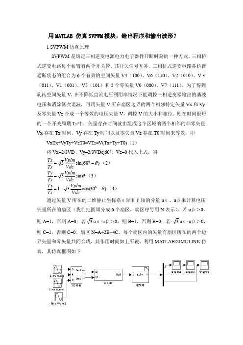
利用MATLAB/SIMULINK 仿真,其仿真框图如下图3.1 基于SVPWM逆变器仿真框图图3.1中SVPWM模块为根据空间矢量控制方法确定电力电子器件开关时刻模块。
根据SVPWM三相并网逆变器仿真报告
基于SVPWM三相并网逆变器仿真报告目录1. SVPWM逆变器简介 (1)2. SVPWM逆变器基本原理 (2)2.1. SVPWM调制技术原理 (2)2.2. SVPWM算法实现 (5)3. SVPWM逆变器开环模型 (11)3.1. SVPWM逆变器开环模型建立 (11)3.2. SVPWM逆变器开环模型仿真分析 (14)4. SVPWM逆变器闭环模型 (16)4.1. SVPWM逆变器闭环模型建立 (16)4.2. SVPWM逆变器闭环模型仿真分析 (17)1.SVPWM逆变器简介三电平及多电平空间矢量调制(Space Vector Pulse Width Modulation,SVPWM)法是建立在空间矢量合成概念上的PWM方法。
它以三相正弦交流参考电压用一个旋转的电压矢量来代替,通过这个矢量所在位置附近三个相邻变换器的开关状态矢量,利用伏秒平衡原理对其拟和形成PWM波形。
空间矢量调制方法在大范围调制比内有很好的性能,具有很小的输出谐波含量和较高的电压利用率。
而且这种方法对各种目标的控制相对容易实现。
SVPWM技术源于三相电机调速控制系统。
随着数字化控制手段的发展,在UPS/EPS、变频器等各类三相PWM逆变电源中得到了广泛的应用。
与其他传统PWM技术相比,SVPWM技术有着母线电压利用率高、易于数字化实现、算法灵活便于实现各种优化PWM技术等众多优点。
2. SVPWM 逆变器基本原理2.1. SVPWM 调制技术原理SVPWM 的理论基础是平均值等效原理,即在一个开关周期内通过对基本电压矢量加以组合,使其平均值与给定电压矢量相等。
在某个时刻,电压矢量旋转到某个区域中,可由组成这个区域的两个相邻的非零矢量和零矢量在时间上的不同组合来得到。
两个矢量的作用时间可以一次施加,也可以在一个采样周期内分多次施加,这样通过控制各个电压矢量的作用时间,使电压空间矢量接近按圆轨迹旋转,就可以使逆变器输出近似正弦波电压。
- 1、下载文档前请自行甄别文档内容的完整性,平台不提供额外的编辑、内容补充、找答案等附加服务。
- 2、"仅部分预览"的文档,不可在线预览部分如存在完整性等问题,可反馈申请退款(可完整预览的文档不适用该条件!)。
- 3、如文档侵犯您的权益,请联系客服反馈,我们会尽快为您处理(人工客服工作时间:9:00-18:30)。
Xi’an Jiaotong University, China xjtulining1983@ Abstract-- A fast algorithm for three-level space vector pulse wide modulation (SVPWM) in neutral point clamped (NPC) inverters based on traditional three-level sinusoidal pulse wide modulation (SPWM) is proposed. The acting time relation of each state in each phase is got by deeply researching the similarities and differences of three-level SPWM and SVPWM. This algorithm can realize all kinds of state sequences easily, it does not need to do trigonometric function, irrational operation and coordinate transformation, it just needs ordinary arithmetic, therefore the calculation is very simple and the result is much more accurate. The fast algorithm can be easily implemented on microprocessor and the executing speed is faster than the conventional threelevel SVPWM algorithm. Index Terms-- fast algorithm, three-level SVPWM, acting time relation, state sequences.
Fig.1 Schematic diagram of three-level SPWM
B. Conventional three-level SVPWM
020
120
220 Vref
220 Vref 4 210
Sec. 1
021
121 010
221 110
221 110 2 222 111 000 1 211 100
I. INTRODUCTION Since the development of power electronics, many kinds of PWM technologies have been used in power electronic circuits, SPWM and SVPWM are two mostly used schemes of them [1]. SPWM uses triangular carrier to compare with sinusoidal wave to get pulse signals, it realizes easily, yet the voltage utilization is low. SVPWM can obviously reduce the current harmonic component and raise the utilization ratio of the power, however, in traditional SVPWM, nonlinear operation is needed to be carried out, such as the sine and arctan function etc, these operations will influence the control speed of the system. In threelevel NPC inverters, the simplified or fast algorithm of three-level SVPWM is attracting more and more attention, due to the complexity of three-level SVPWM[2][3][4]. Some simplifications to SVPWM algorithms have already been proposed in literatures[4][5][6][7][8][9][10], yet some of these algorithms still have to use look-up tables to pick out the switching state vectors which compose the reference vector, some of them can not change the switching state sequences easily. In this paper, a fast algorithm for three-level SVPWM in NPC inverters is discussed, it is very fast and simple to implement, further more, it can realize different state sequences easily, therefore it can be used in many different situations.
978-1-4244-5670-3/10/$26.00 ©2010 IEEE
53
reference vector Vref, secondly, it identifies the sector and triangle in which the reference vector falls, as shown in Fig. 2. After the triangle is identified, a look-up table with as many entries as the number of triangles is used to find the vectors to be used. Then the SVPWM algorithm carries several calculations to obtain the duty ratios of those vectors, at last, it decides the switching state sequences and transforms switching state into gate pulses. Fig.3 shows some commonly used state sequences of three-level SVPWM. In the six sequences, SVPWM1 is an asymmetrical sequence, it uses two zero switching states, there are six communications per switching cycle. SVPWM2 uses symmetrical sequence to get low THD, there are also two zero switching states, therefore the
2010 2nd IEEE International Symposium on Power Electronics for Distributed Generation Systems
A Fast Algorithm for Three-level SVPWM in NPC Inverters Based on Traditional Three-level SPWM
210 3 200
Hale Waihona Puke 022122 011222 111 000 112 001 212 101
211 100
200
012
201
Tri.1: 000-100-110-111-211-221-222 Tri.2: 100-110-210-211-221 Tri.3: 100-110-210-211 Tri.4: 110-210-211-221
II. FAST ALGORITHM FOR THREE-LEVEL SVPWM A. Traditional three-level SPWM Fig.1 shows the schematic diagram of three-level SPWM in regular sampling method. There are two carriers in three-level SPWM, in one switch period, if the reference voltage is larger than zero, the reference compares with the upper carrier, otherwise, it compares with the lower carrier. From Fig.1, it is clear that in traditional three-level SPWM, there are two states in each phase and the wave form of each phase is symmetrical per switch cycle, so, totally, in a three-phase system, there are six commutations per switch cycle.