示波器手册
固纬GOS-6103C GOS-6103示波器说明书
操作手册i索引页次1. 产品介绍………………………............................. 1-1.简述…………………………………………………..… 1-2.特性…..…………………………………………………1 12 2. 技术规格………………………….…………………..43. 使用前之注意事项......................................... 3-1.包装之拆卸.................................................... 3-2.检查电源电压................................................. 3-3.操作环境........................................................ 3-4.仪器的安装和操作........................................... 3-5.CRT 的亮度................................................... 3-6.输入端子的耐压. (7)7 7 8 8 8 84. 面板介绍...................................................... 4-1.前面板.................................................... 4-2.后面板. (9)11 305. 操作方式……………………………………………… 5-1.读出显示器………………..………………………….. 5-2.输入讯号的连接………………....…………………… 5-3.调整和检查……………………………………………. 5-4.功能检查……………..…..……………………………. 5-5.基本操作……………...………….….………………… 5-6.量测应用………………………………………………..3131 33 34 36 38 466. 一般维修...................................................... 6-1.保险丝的更换................................................. 6-2.电源电压........................................................ 6-3.清洁方法.. (51)51 51 527. 方块图 (53)操作手册ii安全标示以下之各种安全术语可能会出现在这本操作手册或是本产品上:警告: 表示产品在某一确认情况下或是在实际应用上之结果可能会对人体产生伤害甚至于造成生命之损失。
示波器SS-7802A中文说明书

示波器SS-7802A操作手册介绍●感谢您购买此款IW A TSU 仪器。
●请在使用仪器前阅读本操作手册,并放于手头以备后查。
●为保证此仪器的安全使用,避免给用户和财产带来损失,请您仔细阅读并注意后文中的“警告”与“小心”。
●本使用手册主要讲述使用的注意事项、操作方法、使用示例以及性能。
注意●这本手册的部分内容在没有被警告的情况下,其性能与作用可能被修改。
●未经IW A TSU 许可,禁止翻印手册内容。
●关于此款仪器,如有疑问,请与 IW A TSU 按手册末尾注明的地址或与我们的销售部门联系。
安全防范为保证此仪器的安全使用,避免给用户和财产带来损失,请您仔细阅读后文中的“警告”与“小心”,并注意观察仪器盘上的相应符号。
手册中所用“警告”与“小心”的定义面板符号的解释符号 说明此符号贯穿全手册使用并附带说明,以防操作者受伤、仪器受损。
表示框架或底盘终端。
务必阅读本页以确保安全警告安装●请勿在爆炸性气体环境中使用,否则将会引起爆炸。
●如仪器发生冒烟、臭味、异常噪音现象,请您立即停止测量以防电击或着火。
关掉被测仪器,切断电流输出。
请与IWA TSU 按手册末尾注明的地址或与我们的销售部门联系。
请勿擅自尝试修理设备。
电源●请在额定操作电压范围内使用仪器。
如超出额定范围使用,竟有可能发生电击、着火或故障。
操作电压范围注于背面面板上。
此仪器使用单相电压:100V AC, 110 到120V AC,或220 到240V AC。
●使用三相接地电源线。
将附带的三相电源线接到三线插座上,电源线即可接地。
如不接地,将可能发生电击或设备损伤。
当电源为两线插座时,请使用三相/两相转换适配器,并将三相/两相转换适配器的接地线接地。
●使用两相电源线可能引发电击。
●电源线请勿使用受损的电源线或适配器,否则可能引发着火或电击。
如果电源线破损,请与IWA TSU 按手册末尾注明的地址或与我们的销售部门联系维修。
●请勿改装电源线。
NDS 双通道系列数字存储示波器 用户手册说明书

NDS双通道系列数字存储示波器用户手册官方微信,一扫即得如需资料下载,请登录:/download2023.03版本V1.6.3©福建利利普光电科技有限公司版权所有,保留所有权利。
产品受专利权的保护,包括已取得的和正在申请的专利。
本文中的信息将取代所有以前出版资料中的信息。
本手册信息在印刷时是正确的。
然而,福建利利普光电科技有限公司将继续改进产品并且保留在任何时候不经通知的情况下变动规格的权利。
是福建利利普光电科技有限公司的注册商标。
福建利利普光电科技有限公司福建漳州市蓝田工业开发区鹤鸣路(原横三路)19号利利普光电科技楼Tel: 4006-909-365 Fax:************Web: E-mail:*************.cn保修概要本公司保证,本产品从本公司公司最初购买之日起3年(配件1年)期间,不会出现材料和工艺缺陷。
配件如探头、电池等保修期1年。
本有限保修仅适于原购买者且不得转让第三方。
如果产品在保修期内确有缺陷,则本公司将按照完整的保修声明所述,提供维修或更换服务。
如果在适用的保修期内证明产品有缺陷,本公司可自行决定是修复有缺陷的产品且不收部件和人工费用,还是用同等产品(由本公司决定)更换有缺陷的产品。
本公司作保修用途的部件、模块和更换产品可能是全新的,或者经维修具有相当于新产品的性能。
所有更换的部件、模块和产品将成为本公司的财产。
为获得本保证承诺的服务,客户必须在适用的保修期内向本公司通报缺陷,并为服务的履行做适当安排。
客户应负责将有缺陷的产品装箱并运送到本公司指定的维修中心,同时提供原购买者的购买证明副本。
本保证不适用于由于意外、机器部件的正常磨损、在产品规定的范围之外使用、使用不当或者维护保养不当或不足而造成的任何缺陷、故障或损坏。
本公司根据本保证的规定无义务提供以下服务:a) 维修由非本公司服务代表人员对产品进行安装、维修或维护所导致的损坏;b) 维修由于使用不当或与不兼容的设备连接造成的损坏;c) 维修由于使用非本公司提供的电源而造成的任何损坏或故障;d) 维修已改动或者与其他产品集成的产品(如果这种改动或集成会增加产品维修的时间或难度)。
Kikusui COS5042TM示波器用户手册说明书
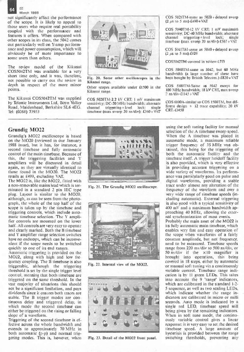
stable. The B trigger modes are continuous delay and triggered delay, in which mode the second timebase can
either be triggered on the rising or falling slope of a waveform.
M022, along with high and low fre-
quency coupling. The B timebase is also
triggerable, although the triggering
threshold is set by the single trigger level
100 MHz bandwidth; 18 kV CRT, max sweep 2 ns/div-f1145 -VAT
COS 6100A -similar to COS 1500TM, but dif-
ferent design ÷ 12 trace capability; 20 kV
CRT. -11450
this, the triggering facilities and Y
amplifiers will be discussed in detail again, as they are virtually identical to those found in the M020. The M022
half. All controls are very easy to operate
and clearly marked. Both the B timebase
力科示波器使用手册

Digital OscilloscopesWave r unner-2 Qu i c k s t a r t to Signal Vi e w i ngAnalo g Pe r s i s t e n c e ™Press A N A L O G P E R S I S T to access the power of An a l o g Pe r s i s t e n c e.The three-dimensional view shows va r i a tions in a wave f o r m as i n te n s i t y or co l o r -g r aded va ri ati o n s .Press D I S P L AY to custo m i z e the display.Press Z O O M for a close-up view of signal e the zoo m co n t r ols to magnify and inspe c t the signal,the soft k eys to change the zoom view,l o ck the zoom tra c es with multi-zoo m ,and to auto m a t i c ally scan the wave f o r m .1 .Co n n e c t your signal.When using a pro b e,Pro B u s ®a u t o m a t i c ally sets the ve r t i c al scale factor and HFP prob es a u t o m a t ic ally light-up with the tra c e co l o r .2 .Press A U T O S E T U P and view.3 .Press “ U n d o ”to reve r t back to a previous setting.Adjust the T I M E / D I V,and SMART Me mo r y a u t o m a t i c ally assure s the maximum re s o l u -tion for each time-base setting.Press a C H A N N E Lb u t t o n ,and use the co n t r ol knobs to s e l ec t and adjust that c h a n ne l ’s Vo l t s /D i v and offset settings.Press tw i c e to tog g l e the channel be t we e n On and Of f .Se l e c ts a pre- or po s t -t r igger e to v i e w the signal eve n t s p r ior to the tri g g e r po i n t.Presets the tri g g e r d e l a y to ze r o.Quick Zoo mPress a C H A N N E L b u t t on to viewthe menu.Wave p i l o t T Mfor Quick Me a s u r e m e n ts and An a l ysis with InsightPressW AVEP I L OT and M E A S U R E for a quick view of up to 26 standard p a r a m e t e r s ,to set up a custom para m e t e r ,or a pass/fail te s t .Se l e c t para m e t er measure m e n ts with statistics for multiple s w e e p s .1 .Se l e c t D A S H B O A R D for an exte n s i v e para m e t er set,or select standard Time or Voltage measure m e n t s .2 .The D A S H B O A R D v i e w is co n text sensitive so when youv i e w a signal,h i s t og r a m ,or Tra c k V i e w the measure m e n ts a r e re l e va n t.3 .C U S T O M t u r ns para m e t er statistics On or Off and allowsyou to define your own set of measure m e n t s .Pa r a m e t er Me a s u r e m e n t sMe a s u r e and An a l y z e Wave f o r m sFor math proce ssi n g ,Press button A,B,C ,or D to set up a zoo m t r a c e.1 .Press S E T U P2 .Se l e c t U S E M AT H and choose a funct i o n .Math and analysis can be pe r fo r med on any tra c e.Vi e w the result for tra c e A,B,C ,or D.Press A N A L O G P E R S I S T and select H I S T O R Y to maximize the upd a te rate and to display a signal in An a l o g Pe r s i s t e n c e and ins e q u e n c e mod e .Trigger time stamps for up to 4,000 acquisitions a r e displaye d .For further analysis of an acquisition segment,H i s t og r am the full Histo r y,then use P LAY and R EV E R S E to scan it in s e q u e n c e.Standard Measurementsa m p l Am p l i t u d ea r e a I n te g r al of wave f o r m dat ab a s e Lower of two most probable states cyc l e s cyc l e s Nu m b er of cycles of a pe r i o dic wave f o r m c m e a n Cyclic mean:The ave r age of wave f o r m dat a c r m s Cyclic root mean squard e l a y Time from trigger to tra n s i t i o n∆d l y Time be t ween 50% level of two source s d u t y Du t y cyc l e :Width as pe r ce n tage of pe r i o d f a l lFall time from 90% to 10%f 80-20%Fall time from 80% to 20%maximum The highest po i n t in a wave f o r m f r e q Fre q u e n c yminimum The lowest po i n t in a wave f o r m m e a n The ave r age of data for time-domain wave f o r m ove r +Ove r s h o ot po s i t i v e ove r -Ove r s h o ot negat i v e p k p k Pe a k -t o -p e a kpe r i o d Pe r i o d of a cyclic signalr 20-80%Rise time from 20% to 80%p h a s e Phase diffe r e n c e be t ween signal analyzed and ri s e Rise time from 10% to 90%signal used as a re f e r e n c es d e v St a n d a r d dev i a tion of data be t ween the cursors.rm s Root mean square of data be t ween the cursors w i d t hWidth of cyclic signal:All wave f o r m pulses to p Higher of two most probable state sa r e ave r aged then displaye dx a m n Ho r i z o n tal position of the smallest data va l u e x a m x The hori z o n tal position of the largest data va l u eWaverunner-2 Options:WAVA - WaveAnalyzer and EMM - Extended Math and Measurementc sde v Cyclic standard dev i a t i o n∆c2d±∆ clock to data ± (setup and hold time)cmedian Cyclic median:The ave r age of base and top∆t@lv The transition time be t ween selected levels on values over an inte g r al number of cyc l e sa single tra c e or be t ween two tra c e s f i r s t I n d i c ates value of hori z o n tal axis at left cursor m e d i a n The ave r age of base and top va l u e s l a s t Time from trigger to last (ri g h tmost) cursor po i n ts Nu mb er of po i n ts be t ween the cursors r @l e ve l Rise time be t ween selected voltage leve l s f @l e vel Fall time be t ween selected voltage leve l s dur Time be t ween triggers in segment /h i s t o r y modet @l e ve l Time from trigger (t=0) to crossing at a leve lStandard Math Tools (Signal Processing)Arithmetic Sum (add),Di f f e r e n c e (subtra c t ),Prod u c t (multiply),Ratio (divide)Ave r aging Summed ave r age of up to 4 000 swe e p s;Co n tinuous ave r age from 1:1 to 1:1024 we i g h t i n gExt r e m a Enve l o p e,f l o o r,and roo fF F T Fast Fo u r ier Tra n s f o r m to 50,000 po i n t s:FFT Ty p e s Power Spe c t r u m,P h a s e,Ma g n i t u d e.Wi n d o ws :Fl a t To p,Re c t a n g u l a r,Bl a c k man Ha r ri s,Von Ha n n,Ha m m i n gOther Fu n c t i o n s I d e n t i t y,Ne g a tion (Inve r t ),Sine x/xResample To deskew as well as resample signalsRe s c a l e Assign phys i c al units and re s c a l eE R E S En h a n c ed Resolution for up to 11 bits of ve r t i c al re s o l u t i o nWaverunner-2 Options:WAVA_WaveAnalyzerAll standard mat h,m e a s u r e m e n t,and signal processing tools plus:Extended Ave r aging Su m m e d.Ave r age of up to one million wave f o r m s.Co n tinuous ave r age from 1:1 to 1:1024 we i g h t i n gExtended FFT Fast Fo u r ier Tra n s f o r m to one million po i n t sFFT Ave r a g e,Power Ave r a g i n g,Re a l,Power De n s i t y,Real + ImaginaryH i s t og r a m s*Gra p h i c al analysis with Histog r ams and Histog r am An a l y sis Pa r a m e t e r sWAVA : 2 billion eve n t sE M M:200 eve n t sH i s t og r am Pa r a m e t e r sav g ave r age of data values in histog r a mf w h m full width (of largest peak) at half the maximum binf w x x full width (of largest peak) at xx% the maximum binh a m p l h i s t og r am amplitude be t ween two largest pe a k sh b a s e h i s t og r am base or leftmost of two largest pe a k sh i g h highest data value in histog r a mh m e d i a n median data value of histog r a mh r m s rms value of data in histog r a mhto p h i s t og r am top or ri g h tmost of two largest pe a k sl o w l o west data value in histog r a mm a x p po p u l a tion of most po p u l a ted bin in histog r a mm o d e d a ta value of most po p u l a ted bin in histog r a mpct l d a ta value in histog r am for which specified x% of po p u l a tion is smallerp k s n u m b er of peaks in histog r a mra n g e d i f f e r e n c e be t ween highest and lowest data va l u e ss i g m a s t a n d a r d dev i a tion of the data values in histog r a mto t p total po p u l a tion in histog r a mx a p k x-axis position of specified largest pe a kTrending* Plot a para m e t er versus time or versus another para m e t e rOther funct i o n s*Ab s o l u t e Va l u e,Re c i p r ocal (1/x),Sq u a r e,Sq u a r e Roo t,De r i v at i v e,I n te g r a l,Exp (base e),Exp (base 10),Log (base e), Log (base 10)DFP_Digital Filter PackageLinear-phase Fi n i t e Impulse Re s p onse (FIR) filte r s:Low Pa s s,High Pa s s,Band Pa s s,Band Sto p,Raised Co s i n e,Raised Root Co s i n e,Ga u s s i a nUp to 4 filters can be ca s c a d e d.Design a custom filter then download the filter coe f f i c i e n ts into the Wave P ro sco p e with DSOFi l t er utility.JTA_Jitter and Timing AnalysisJi t t e r T rack for a time co r re l a ted gra p h i c al view of cycle to cycle para m e t er va r i a t i o n.PMA1 – Power Measure AnalysisPower Me a s u r e An a l y sis provides para m e t r ic and gra p h i c al analysis of power dev i c e mod u l a tion and line power analys i s.* Also included with EMMWave r u n n e r - 2Tri g g e r i n gLevel indicato r sHo r i z o n tal delay (tri g g e r )position indicator I c ons indicate the ty p e and c h a r a c te r istics of the tri g g e rin use.Setup signal conditions Se l e c t pulse ty p e Se l e c t co u p l i n g Se l e c t trigger source Se l e c t trigger ty peNa meDe s c rip t i o nEd g e Se le c t po s i t i v e or negat i v e slope and hold-off by time or eve n t s .Wi n d o wSet a window around the trigger leve l .Trigger whenever the signal crosses outside the w i n d o w in either dire c t i o n .Waverunner-2 Basic TriggersAc c esses the trigger setupm e n u .Arms the tri g g e r .The sco p e triggers once when the triggerconditions are met and then displays the signal.Triggers even if a signal is notp r e s e n t.Triggers whenever the tri g g e r conditions are met.Sets the trigger leve l .Preve n ts the sco p e fro mt r i g g e r i n g .Flashes when a trigger oc c u r s .The text indicates stat u s .PressW AVE P I L OT and G RA P H for quick access to powe r ful pro b l e m solving fe a t u r e s .Qu i c k ly identify the problem with spe c i a l v i e ws :H i s t og r a m s ,F F T ,Tra c k V i e w,and Ji t t e r T ra c k .1 .Se l e c t the ty p e of view and the para m e t er or funct i o n .2 .Setup the view.3 .Se l e c t Graph and Tra c k V i e w or Ji t t e r T rack for a time- co r re l a ted view of measure m e n ts and you can visually t r ack down signal errors and anomalies.His t og r ams are fast and simple to set up.Press W AV E P I L OT a n d G RA P H ,dial in the measure para m e t e r ,s e l e c t the Histog r am Se t u p co n d i t i o n s ,then press A U T O S E T U P h i s t og r a m .Graph Pa r a m e t er Di s t r ibutions Get measure m e n ts that make sense! Press W AV E P I L OT and G RA P H ,then M E A S U R E ,for a quick,co n text -s e n s i t i v e para m e t er assess-m e n t of the chara c te r istics of Tra c k V i e ws.Graph andMe a s u r e m e n tsGraph Vi e wsRo t a r y co n t r o l s adjust the hori-zo n tal po s i t i o n and magnificat i o n of the selecte d zoom tra c e.Se l e c t a zoom tra c e fo r setup of signal proce s s -i n g .The analysis co n t r o l s a f f e c t the selected tra c e ( A ,B , C ,D ).Press tw i c e to toggle be t ween On and Of f .Quick Zooma u t o m a t i c ally displays 10X magnified tra c e s of all signals on multi-g r i d sProvides dire c t access to m a t h e m a t i c al signal p r oce s s i n g .An a l y sis Co n t r olsR S -232-CCe n t r onics co m p a t i b l e Pri n ter Po r tVGA Mo n i t or Po r tPC Ca r d Slot (optional)Su p p o r ts SRA M ,ATA Fl a s h ,a n d Ha r d Dri v e PC Ca r d s .50 Ω BNC Input for a 10 MHz Re f e r e n c e Cl o ckAC Line Input:Au t o m a t i c a l l y senses and co n f i g u r es line voltage and f r e q u e n c y.10 Base T Et h e r net Po r t (optional)Sales and Se r v i c eTh r oughout the Wo r l d Co r po r ate He a d q u a r te r s700 Chestnut Ridge Ro a d Chestnut Ri d g e ,NY 10977U S Aht t p ://w w w . l e c r oy. c o m Le C roy Sales Of f i c e s :Asia:Hong KongPhone (852) 2834 5630Fax (852) 2834 9893Austria:Markersdorf Phone (43) 2749 30050Fax (43) 2749 30051Benelux:The Netherlands Phone (31) 40 211 6998Fax (31) 40 211 6999France:Les UlisPhone (33) 1 69 18 83 20Fax (33) 1 69 07 40 42Germany:Heidelberg Phone (49) 6221 827 00Fax (49) 6221 834 655Italy:VenicePhone (39) 41 456 97 00Fax (39) 41 456 95 42Japan:OsakaPhone (81) 6 6396 0961Fax (81) 6 6396 0962Japan:TokyoPhone (81) 3 3376 9400Fax (81) 3 3376 9587Japan:TsukubaPhone (81) 298 56 0961Fax (81) 298 56 0962Korea:SeoulPhone (82) 2 3452 0400Fax (82) 2 3452 0490Spain:MadridPhone:(34) 91 640 11 34Fax:(34) 91 640 06 40Switzerland:Geneva Phone (41) 22 719 2111Fax (41) 22 719 2230U.K.:AbingdonPhone (44) 1 235 536 973Fax (44) 1 235 528796U.S.A.:Chestnut Ridge Phone (1) 845 578 6020Fax (1) 845 578 5985Co p y r i g h t © Ja n u a r y 2001Le C roy,Pro B u s ,and SMART Trigger are re g i s t e r ed tra d e m a r ks of Le C roy Co r po r at i o n .All ri g h ts re s e r ve d .Wave P ro,Wave r u n n e r ,L i t e r u n n e r ,Ji t t e r W i z a r d,Ji t t e r T ra c k ,Ji t t e r P ro,An a l o g Pe r s i s t e n c e,and Act i v eDSO are tra d e m a r ks of Le C roy Co r po r at i o n .I n f o r m a tion in this publication supersedes all earlier ve r s i o n s .Spe c i f i c ations subject to changewithout notice.Rear PanelTh r ee dimensional view a l l o ws va r i a tions in a wave f o r m as inte n s i t y or color graded va r i a t i o n s.。
是德科技keysight9000 系列示波器说明书技术指标使用手册,原安捷伦

逻辑通道数 16 16 16 16
2
为什么 Infiniium 9000 系列是用户值得信赖的、 能够解决各种测试和调试难题的示波器 ?
它是一台三合一的仪器
1. 示波器 : Infiniium 系列示波器的强大功能加上出色的技术指标为您提供高保 真的信号表征。
2. 逻辑分析仪 : 快速深存储器让您看到关键的数据和定时关系。 3. 协议分析仪 : 全球首款基于示波器的协议查看器,具有多种观察能力。
● CAN
● FlexRay
● I2C
● JTAG
● LIN
● MIPI D-Phy
● PCle
● RS-232/UART
● SATA
● SPI
● USB
● 8B/10B
通过时间关联跟踪游标在物理层信息和协议层信息间进行快速跟踪观察。使用波形符号表 和业内首款多列表协议查看器显示协议内容。协议数据包选项卡显示随时间变化的协议数 据包的高级视图。
Agilent Infiniium 9000 系列示波器
技术资料
提供最广泛的测量能力
如果您还没有购买安捷伦示波器 , 为什么不考虑现在订购一台 ?
对于大多数工程师来说,可能永远也无法预料下一个项目将会出现怎样 的挑战。这就需要拥有一款能够在调试和测试方面适应各种挑战的示波器。
体 验 InfiniiVision 9000 系 列 示 波 器 卓 越性能的最佳方法就是亲自去看一 看。欢迎您现在就与安捷伦科技公 司联系。
TBS2000系列示波器用户手册说明书
TBS2000系列示波器用户手册Copyright©Tektronix.保留所有权利。
许可软件产品由Tektronix、其子公司或提供商所有,受国家版权法及国际条约规定的保护。
Tektronix产品受美国和外国专利权(包括已取得的和正在申请的专利权)的保护。
本文中的信息将取代所有以前出版的资料中的信息。
保留更改技术规格和价格的权利。
TEKTRONIX和TEK是Tektronix,Inc.的注册商标。
TekVPI是Tektronix,Inc.的注册商标。
TekSecure和TekSmartLab是Tektronix,Inc.的商标。
Tektronix联系信息Tektronix,Inc.14150SW Karl Braun DriveP.O.Box500Beaverton,OR97077USA有关产品信息、销售、服务和技术支持:在北美地区,请拨打1-800-833-9200。
其他地区用户请访问,以查找当地的联系信息。
TBS2000系列担保Tektronix保证,本产品从授权的Tektronix分销商最初购买之日起五(5)年内不会出现材料和工艺缺陷。
如果在保修期内证明产品有缺陷,根据用户的选择,Tektronix将或者修复有缺陷的产品且不收部件和人工费用,或者更换有缺陷的产品。
电池不在保证范围内。
Tektronix作保证用途的部件、模块和更换产品可能是全新的,或者经修理具有相当于新产品的性能。
所有更换的部件、模块和产品将成为Tektronix的财产。
为得到本保证声明承诺的服务,客户必须在保修期内向Tektronix通报缺陷,并为服务的履行做适当安排。
客户应负责将有缺陷的产品打包并运送到Tektronix指定的服务中心,请预付运费,并附带客户购买证明副本。
如果产品运送到Tektronix维修中心所在国之内的地点,Tektronix应支付向客户送返产品的费用。
如果产品送返到任何其他地点,客户应负责支付所有的运费、关税、税金及任何其他费用。
示波器用户手册说明书
Unique Capabilities.Ultimate Performance.Ultra-High Precision.Thanks to rapid advances in technology,accurate,real-time waveform analysis is more important than ever,especially in digital and IT applications.With its varying brightness and continuous acquisition, the analog scope brings a real-time statistical dimension to the viewed waveform that is simply not possible with digital storage oscilloscopes.Featuring ultra-high brightness and ultra-high speed response that surpasses even the latest digital oscilloscopes,IwatsuÕs ultimate line of analog scopes make it possible to view natural waveforms across the widest possible frequency range with the highest-possible brightness inÒreal timeÓ.So give yourself the analog advantage with IWATSU. Nothing else measures up.ThereÕs a world of waveforms that only Analog cancapture!Specially-designed gate array with built-in CPU Extra-bright, extra-sharp, Japan-made, IWATSU-original CRTIWATSU-developed LSIs and ICs IWATSU-developed preamp ICWide-Bandwidth Analog Oscilloscope Lineup ● DC - 1GHz/600MHz (50Ω) wide frequency bandwidth ● Fastest sweep of 200 ps/div ● Ultra-fast writing speed of 10 div/ns can capture 6 div amplitude, 500 ps rise time pulse● DC - 500MHz (1 M Ω, passive probes areoptional), 4 CH● Sharp traces and high-resolution color display800 x 480 dots● Versatile output interface and documentationfunctions<Built-in printer, LAN interface, ATA card slot,video output (NTSC/PAL)>TS-81000/TS-80600● DC - 470/400/300MHz, 4 CH, 10 traces [SS-7847A]* DC - 470MHz (-3 dB) at 5 mV - 50 mV/div* DC - 440MHz (-3 dB) at 2 mV , 100 mV - 5 V/div● HDTV , NTSC, PAL/SECAM-compatible full TVtriggering with clamping function● ±2% accuracy for vertical axis sensitivity ● Bright and sharp display with 20 kV acceleratingvoltage CRT (Japan made)● Maximum sensitivity of 2 mV/div ● Input offset function ● 6-digit frequency counter ● Quick auto setup ● Save/recall of up to 256 panel settingsSS-7847A/SS-7840A/SS-7830ATS-Series Analog Storage OscilloscopesSS-Series Analog Oscilloscopes4● DC - 50MHz, 2 CH + ext. trigger input, 3 traces(SS-7805A) /DC - 40MHz, 2 CH + ext. trigger input, 3 traces(SS-7804A)● Cursor measurement function● CH2 output● ±2% accuracy for vertical axis sensitivity● Bright and sharp display with 16 kV accelerating voltage CRT (Japan made)● Full TV triggering with TV line selection capability ● 5-digit frequency counter● DC - 100MHz, 3 CH, 8 traces● CH3 sensitivities of 50 mV, 100 mV , 500 mV/div● Save/recall of up to 32 panel settings (SS-7811A only)● Quick auto setup● ±2% accuracy for vertical axis sensitivity● Bright and sharp display with 16 kV accelerating voltage CRT (Japan made)● Cursor measurement/panel settings readout function● Full TV triggering with field and line selection, HDTV● CH2 output ● Maximum sensitivity of 2 mV/div,fastest sweep of 1 ns/div● 5-digit frequency counter● DC - 20MHz, 2 CH + ext. trigger input, 2 traces● Cursor measurement function● ±2% accuracy for vertical axis sensitivity● Full TV triggering with TV line selection capability● 5-digit frequency counter ● Single-sweep function5● DC - 200MHz, 3 CH, 8 traces● CH3 sensitivities of 50 mV, 100 mV, 500 mV/div● Save/recall of up to 32 panel settings ● Quick auto setup● ±2% accuracy for vertical axis sensitivity● Bright and sharp display with 16 kV accelerating voltage CRT (Japan made)● Cursor measurement/panel settings readout function● Full TV triggering with field and line selection, HDTV● CH2 output ● Maximum sensitivity of 2 mV/div,fastest sweep of 1 ns/div● 5-digit frequency counter23451 H igh-resolution, 5.8-inch color LCD (800 x 480 dpi)Provides a sharp, bright waveform display, with color assignment from 7 colors (white, red, blue, yellow,magenta, cyan, green) for persistence and storedwaveforms.2 P C Card slotFor storage of display image and setup data.3 B uilt-in 6-digit frequency counter(2Hz to 1GHz/600MHz, accuracy ±0.01%)4 P ersistencePersistence time selectable from 0 to infinity.Color display also available.5 1GHz maximum frequency bandwidth1GHz/600MHz frequency bandwidth for CH1/CH2;500MHz for CH3/CH4. (SS-101R passive probe isoptionally available)6 2 power supply connectors for active probesFET probes SFP-5A (1GHz)/SFP-4A (800MHz),current probes SS-250 (100MHz)/SS-240A (50MHz) are available as an option.7 D ual delayTwo delay times provided for B sweeps, allowing delayexpansion at two positions.8 P rint screenHard copy to the built-in printer, ATA card and Network9 S ave/RecallUp to 256 panel setups and six reference waveformscan be save/recalled.0 C ursor measurement∆V or ∆t selectable. Simultaneous 4-cursorsmeasurement also available.! Q uick auto setupAutomatically displays the input waveform in theoptimum range. Applicable to both CH1 and CH2with a frequency range from 50Hz to 200MHz.@ B uilt-in printerPrints out the hard copy of displayed waveform.(Printer speed max. 10 mm/sec)* Please visit our Web site, and confirm our recommendation for the PCMCIA card.http://www.iti.iwatsu.co.jp/e/6Video output (Conposite, 1 V)Z axis input(0.5 Vp-p, DC - 5MHz)CH2 signal output(20 mV/div, 500MHz/300MHz)Enhanced documentation functionsBuilt-in thermal printer and versatile outputinterfaceA built-in thermal printer and LAN interface (10Base-T) areprovided so you can output measured data directly orBurn-free and shock-freeSince the waveform is stored by the CCD, CRT phosphorsare protected from burning. Durable construction providesexcellent shock resistance.High accuracy 6-digit frequency counterBuilt-in thermal printer, LAN environment, personal computers, external printers, video recorders, monitors, ATA cards, etc. Various output interfaces are provided.- Remote control through LANRemote control available through LAN*.Delivers video signal (NTSC/VGA) via network.Real time waveform monitor is also available.* Please visit our web site to download the software.http://www.iti.iwatsu.co.jp/- Network printer supportHard copy to network printers, available by using the“Network Printer Gateway” software*.* Please visit our web site to download the software.http://www.iti.iwatsu.co.jp/- NTSC outputDisplayed waveforms can be stored as MovingPicture files using an optional video capture unit.- Image file saving (BMP/JPEG)It is possible to save displayed waveforms to an A TA card.7igh-brightness CRT (Japan made)6-inch, meshless CRT with internal graticule displays waveforms with bright and sharp traces. igh-accuracy 6-digit frequency counterA frequency counter with ±0.0025% accuracy is ave/recall functionUp to 256 different setups with 12-character comments can be saved and recalled.ide frequency bandwidth of DC - 470MHzA)/400MHz (SS-7840A)/300MHz (SS-5 P ower supply output terminals for FET orcurrent probeOptional SFP-5A/4A (DC - 1GHz/800MHz) FETprobe and SS-250 (100MHz)/SS-240A (50MHz)current probe can be used.6 P owerful TV triggeringTV-H, ODD, EVEN or BOTH fields can be selected.Line selection is possible from NTSC: 1 - 525H,PAL (SECAM): 1 - 625 and HDTV: 1 - 1125.7 D irect selection of the cursor measurementAlternates ∆t and ∆V. Up to four cursors can bedisplayed simultaneously. 1 E xternal intensity modulation signal input0.5 Vp-p, DC - 5MHz, ±40 V2 C H2 signal output20 mV/div, DC - 200MHz/50 Ω12341432Rear panel 8Frequency counter All models6-digit: SS-7847A/7840A/7830A,5-digit: SS-7821A/7811A/7805A/7804A/7802A The built-in 6/5-digit counter is accurate within a range of0.0025% / ±0.01% and can measure frequencies between 2Hz and 400MHz. Also shows the trigger signal frequencies.Pedestal clamp function (CH1, CH2) for TV signals SS-7847A/7840A/7830A The amplitude of video signals varies dynamically depending on the picture. This function ensures stable observation. DC offset function (CH1, CH2)SS-7847A/7840A/7830A Convenient when you need to observe a signal with very small amplitude superimposed over a signal with large amplitude. Especially useful when observing high-frequency noise superimposed over video signals or ripple of high-voltage DC power supply.CH2 skew adjust SS-7847A/7840A/7830AThe delay time of CH2 in response to CH1 can be adjusted with a range of 1 ns. Therefore, accurate measurement is possible by compensating for the delay time difference between the DC - 470MHz/400MHz/300MHz (all channels), high-sensitivity of 2 mV/div (CH1, CH2)A DC - 470MHz (SS-7847A)/DC - 400MHz (SS-7840A)/ DC - 300MHz (SS-7830A) for all channels. CH1 and CH2 have max. sensitivity of 2 mV/div, ensuring extremely high-quality waveforms.IWATSU-developed bright, sharp CRT All models T o increase signal stability, a preamp circuit has been provided for the IC.9Panel settings save/recall function SS-7847A/7840A/7830A (SS-7821A/7811A: up to 32 setups)Up to 256 panel setups can be saved together with comments (up to 12 characters).Event trigger SS-7847A/7840A/7830AIn addition to the event delay trigger which allows you to trigger (with DC offset control).● HDD magnetic head measurementOutput waveforms from defectivesectors on a hard disk where errorshave occurred are magnified forobservation.● Large-capacity transmission Digitized video data is sent via a high-speed serial transmission line. The TS-81000 accurately displays subtle variations, such as overshoot of serial data signal waveforms.● Evaluation of power-factor improvement circuit (Power supply)The TS-Series displays jitter-contained waveforms with brightness variations inreal time.● Video signalsThe TS-Series accurately displays details of video signals. It can clearly show slow-repetition video signals with ultra-high brightness via the persistence function. The TS-Series has suitable functions for video signals including an HDTV trigger, two types of video scales, aTV clamp, 4-field selector and dual delay.TS-Series: for observation of complex, intermittent signals● Photo multiplier tubeOutput signal voltage variation detectedby the photo multiplier tube.The TS-Series can display clusters ofirregular single-shot signals at ultra-fastspeeds and displayed in real time withslight brightness differences.● Blue laser diode The read/write signals of laser diodes are getting faster as the density of optical storage media increases. The TS-Series can provide solutions for engineers due to its 1GHz/600MHz frequency bandwidth - the widest in the world.● High power laser waveform High-brightness analog oscilloscopes are needed for continuous low-repetition rate pulse signals. The TS-Series can provide a new safety evaluation method as a high-power laser with video output and LAN interface.10The following shows a comparison of analog and digital waveforms, using calibration waveforms from the EMC static electricity discharging immunity testing equipment. The figure on the left shows a waveform captured by an analog storage oscilloscope, while the figure on the right shows a waveform captured by a digital oscilloscope with a 10 GS/s high-speed sampling frequency. When compared to the analog oscilloscope (on the left), you may see an apparent difference in peak level in the first pulsesection. The observed object is a signal with an amplitude of approximately 800 mV. The peak signal is not captured by the digital oscilloscope, possiblybecause correct observationis not possible with the digitaloscilloscope due toinsufficient sampling speed,depending on the waveformsbeing observed. Although thestatic electricity dischargingtest is just an example,it shows that the TS-SeriesAnalog Storage Oscilloscopecan easily capture extra-highspeed signals of this typeand display the capturedwaveform“as it is” in real time.SS-Series: indispensable for a wide range of requirements● Eye-patterns in optical disc manufacturing process When evaluating optical discs such as Blu-ray Discs, HD-DVDs, CDs or DVDs, eye patterns need to be observed. With this analog oscilloscope, accurate observation of the eye patterns of high-speed and high-density media is easily possible. * Blu-ray Disc signal eye pattern waveform ● Video head frequency modulation signals Input and output signals to/from video heads are frequency modulation waveforms. The voltage of recorded or read-out signals to/from the video heads is specified. To observe these FM signals, an analog oscilloscope is indispensable.* VHS deck head signal waveform ● ATM 155 Mbps signal eye patternsThe standard transmission rate for most networked communication systems is 155 Mbps (STM-1). The amount of jitter can be estimated by observing the signal waveform with the eye pattern and following the pulse mask standard. * 155 Mbps signal eye pattern waveformmeasured with SS-7847A (DC - 470MHz)● Full TV triggering TV-V (ODD field, EVEN field, BOTH fields) and TV-H are available. Line number selection in TV-V mode is useful for detailed evaluation of video signals. HDTV can be selected, as well as NTSC or PAL/SECAM (except for SS-7805A/7804A/7802A)● Switching power supply measurementA switching power supply unit with a higher harmonics measure switches the voltage of a commercial power supply at high speed. In terms of circuit operation, switching stops at the zero cross of the AC power supply. To observe this condition, an analog oscilloscope is required. Analog oscilloscopes are also superior when simultaneously observing voltage and current waveforms. In addition, when magnifying a switching waveform for observation on an analog oscilloscope, no complicated operations are required to triggerthe waveform.Captured by digital oscilloscope (10 GS/s)Captured by analog storage oscilloscope 11— A wide range of options for maximum efficiency and optimum performance ArrayTS-Series and SS-Series Options1213Notes for TS-Series Oscilloscopes"#。
数字示波器DL9000系列的中文简易操作手册
MAG dial 8.6节 在放大显示中,旋转此
旋钮改变垂直轴/水平轴 放大率。
第 11 章
使用历史存储功能,显示波形菜 单,并进行检索。 按SHIFT键,再按HISTORY键, 启用HISTORY CLEAR键,清除 历史波形。
第10.5~10.8节 XY显示菜单、FTP分析、波形参数柱状图和 列表及其它设置。当显示打开时,键灯亮。
LEVEL/COUPLING键 第6.3节 调出菜单,设置触发耦合、高频抑制和窗 口比较器等。
4
IM 701310-02C
前面板各部分名称及功能
ACQ键 第7.1,7.2节 调出菜单,设置波形采集模式。
SAMPLING/LENGTH键 第7.3 ~ 7.6节 设置记录长度、等效时间采样、交替和插 补。
SOURCE
LEVEL COUPLING
TRIG MODE/HOLD OFF 第7.1,7.8节 调出菜单,选择触发模式。 按动作触发菜单上的 MODE 键之后,再按 SHIFT 键。
ENHANCED键 第6.17节 调出菜单,设置 TV 触发和串行总线触发。
EVENT INTERVAL键 第6.14 ~ 6.16节 调出菜单,设置事件触发。
· 打印屏幕图像 · 保存数据
第9章 第10章 第11章
第12章 第13章
IM 701310-02C
3
前面板各部分名称及功能
前面板各部分名称及功能
此节简单介绍前面板上各个操作键和旋钮的名称及其相应功能。操作详情请见操作手册的相应章节 (见 )。
垂直轴
CH1 ~ CH4 键 第 5 章
调 出 菜 单 , 切 换 显 示 打 开 /关 闭 通 道、 耦 合 、 探头类型、偏置 电压、带宽限制、放大/缩小垂直 轴、波形标签 。 用 V/DIV旋 钮 设 置 相应通道设置前,请按 这 些 键 中的 一 个 键。打开通道后,相应通道键 会亮灯。
超便携数字存储示波器用户手册-OWON-利利普
超便携数字存储示波器用户手册保修概要本公司保证,本产品从我公司最初购买之日起3年(配件1年)期间,不会出现材料和工艺缺陷。
配件如探头等保修期1年。
本有限保修仅适于原购买者且不得转让第三方。
如果产品在保修期内确有缺陷,则本公司将按照完整的保修声明所述,提供维修或更换服务。
如果在适用的保修期内证明产品有缺陷,本公司可自行决定是修复有缺陷的产品且不收部件和人工费用,还是用同等产品(由本公司决定)更换有缺陷的产品。
本公司作保修用途的部件、模块和更换产品可能是全新的,或者经修理具有相当于新产品的性能。
所有更换的部件、模块和产品将成为本公司的财产。
为获得本保证承诺的服务,客户必须在适用的保修期内向本公司通报缺陷,并为服务的履行做适当安排。
客户应负责将有缺陷的产品装箱并运送到本公司指定的维修中心,同时提供原购买者的购买证明副本。
本保证不适用于由于意外、机器部件的正常磨损、在产品规定的范围之外使用或使用不当或者维护保养不当或不足而造成的任何缺陷、故障或损坏。
本公司根据本保证的规定无义务提供以下服务:a)修理由非本公司服务代表人员对产品进行安装、修理或维护所导致的损坏;b)修理由于使用不当或与不兼容的设备连接造成的损坏;c)修理由于使用非本公司提供的电源而造成的任何损坏或故障;d)维修已改动或者与其他产品集成的产品(如果这种改动或集成会增加产品维修的时间或难度)。
若需要服务或索取保修声明的完整副本,请与最近的本公司销售和服务办事处联系。
除此概要或适用的保修声明中提供的保修之外,本公司不作任何形式的、明确的或暗示的保修保证,包括但不限于对适销性和特殊目的适用性的暗含保修。
本公司对间接的,特殊的或由此产生的损坏概不负责。
目录1.一般安全要求 (1)2.安全术语和符号 (2)3.初级用户指南 (4)初步了解示波器的结构 (5)前面板 (5)右面板 (6)后面板 (7)按键控制区 (8)初步了解示波器的用户界面 (9)如何进行一般性检查 (11)如何进行功能检查 (11)如何进行探头补偿 (12)如何进行探头衰减系数设定 (13)如何安全使用探头 (13)如何进行自校正 (14)初步了解垂直系统 (14)初步了解水平系统 (15)初步了解触发系统 (15)4.高级用户指南 (17)如何设置垂直系统 (18)数学运算功能的实现 (22)使用FFT (24)垂直位置旋钮和垂直伏/格旋钮的应用 (27)如何设置水平系统 (28)如何设置触发系统 (30)单触触发 (31)交替触发 (34)如何操作功能菜单 (38)如何进行采集设置 (38)如何设置显示系统 (40)如何进行保存和调出 (43)如何进行截取波形 (50)如何进行波形录制和回放 (51)如何进行辅助系统功能设置 (56)如何进行自动测量 (61)如何进行光标测量 (65)如何使用自动量程 (68)如何使用内置帮助 (70)如何使用执行按键 (70)5.与计算机通讯 (73)使用USB接口 (73)使用LAN接口 (73)直接连接 (73)通过路由器 (75)使用COM接口 (77)6.应用实例 (78)例一:测量简单信号 (78)例二:测量电路中放大器的增益 (79)例三:捕捉单次信号 (80)例四:分析信号的细节 (81)例五:X-Y功能的应用 (83)例六:视频信号触发 (84)7.故障处理 (85)8.技术规格 (86)9.附录 (90)附录A:附件 (90)附录B:日常保养和清洁 (90)1.一般安全要求请阅读下列安全注意事项,以避免人身伤害,并防止本产品或与其相连接的任何其他产品受到损坏。
- 1、下载文档前请自行甄别文档内容的完整性,平台不提供额外的编辑、内容补充、找答案等附加服务。
- 2、"仅部分预览"的文档,不可在线预览部分如存在完整性等问题,可反馈申请退款(可完整预览的文档不适用该条件!)。
- 3、如文档侵犯您的权益,请联系客服反馈,我们会尽快为您处理(人工客服工作时间:9:00-18:30)。
YB4325数字存储示波器使用手册 江苏绿扬电子仪器集团有限公司 本产品采用的标准:EN61010.1(1993) 测量、控制和实验室电子仪器的安全要求标准 EN-IEC61326-1(1997) 测量和实验室电子仪器的EMC要求 本企业通过ISO9001国际质量体系认证, 本产品按ISO9001标准设计生产。
注意事项 请阅读下列注意事项,以避免人身伤害,延长仪器使用寿命。为了防止可能发生的危险,本产品只可在规定的范围内使用。只有专业技术人员才可进行维修。 防止火灾及人身伤害 *使用适当的电源线。只可使用本产品专用、并且核准该使用国的电源线。 *产品接地。本产品通过电源线接地导线接地,接地导线必须与大地相连。前面板上的接地点同仪器整机连接,用来防止触电和保护人体安全,在和任何接插头连接之前,应确认此接地点和大地连接。 *请勿在无仪器盖板时操作。如盖板或面板已卸下,请勿操作本产品。 *使用适当的保险丝。只可使用符合本产品规定类型和额定值的保险丝。 *在有可疑故障时。请勿操作。如怀疑本产品有损坏,请让专业人员进行检查。 *当用示波器测量电网电压时,一定要事先采用一些附加的措施,若直接将探极接入电网,示波器内的电路会被损坏。 延长仪器使用寿命 储存与使用 *不可在寒冷或炎热环境下使用,仪器工作温度是0℃~40℃。不可将仪器从寒冷的环境中突然搬到炎热的环境或相反进行,这将导致仪器内部和屏幕上形成水汽凝结。 *不可将仪器放在湿度大或灰尘多的地方,最佳使用相对湿度范围是35~90%。 *不可将仪器放置在剧烈震动或强磁场的地方。 操作 *不可堵塞或用金属、导线插入仪器通风孔。 *不可倒置、撞击或用探极、连接线拖拉仪器。 *不可将电烙铁放在仪器框架或表面上。 清理 *用软布沾中性洗涤剂擦拭锈迹或灰尘,不可用强挥发材料,如苯。 校准周期 *为了能够保证仪器测量精度,仪器每工作1000小时或6个月要求校准一次,若使用时间较短,则一年校准一次。 本产品上可能出现如下标记:
序号 符号 说明 序号 符号 说明
1 ! 直流电 7 ○ 关(电源) 2 ~ 交流电 8 +、- 正、负极 3 ! 接地 9 ! 警示触电危险 4 ! 保护接地 10 ! 警示 5 ! 接机架 11 ! 推动开关按入 6 | 开(电源) 12 ! 推动开关按出
简介 谢谢您购买YB4325系列示波器 为了确保正确使用,请在使用之前仔细阅读本说明书。阅闭,请保存好说明书。 该示波器根据严格的质量控制标准设计生产和检验,并通过了一系列环境试验。 售后服务:如果出现任何故障,请与我们销售部或各维修点联系,以便获得快而有效的售后服务。 注意: 该示波器必须在规定的环境中使用,才能保证其处于最佳工作状态。 该示波器在运输过程中,光迹线可能会轻微地发生倾斜。如果出现这一现象,请调节前面板上的光迹旋钮,将光迹调至与水平线平行。 安全警告: *电源插头应有接地保护。 *更换保险丝必须断开输入电源。 *非专业人员请勿打开机箱盖板。 *维修请与我厂维修点或专职维修人员联系。 一.概述 YB4325系列示波器轻颖小巧、使用方便,并具有以下特点: 1) 频率范围广:DC~20MHz -3dB 2) 灵敏度高:最高偏转系数1mv/div 3) 6英寸大屏幕:便于清楚观看信号波形。 4) 数字编码开关:操作灵活,定位准确。 5) 光标读出测量:光标数字读出可使信号观察与测量变得更为迅速精确,屏幕上可提供7种功能(ΔV、ΔV%、ΔVdB、ΔT、1/ΔT、占空比、相位) 6) 触发源:丰富的触发源功能(CH1、CH2、电源触发、外触发)。使用交替触发操作可获得两个不相关电信号稳定的同步显示。 7) 触发耦合:全新的触发耦合电路设计,对各类不同频率、不同电压组合的电信号使用该操作可获得稳定的同步显示。 8) 自动聚焦:测量过程中聚焦电平可自动校正。 9) 触发锁定:触发电路呈全自动同步状态,无需人工调节触发电平。 10) 释抑调节:使各种复杂波形同步更加稳定。 二.仪器配置 提供的标准配置如下: 1) 示波器…………………..1台 2) 探极……………………..2根 3) 使用说明书……………..1本 三.使用注意事项 1)避免过冷和过热。 不可将示波器长期暴露在日光或靠近热源的地方,如火炉。 2)不可在寒冷天气时放在室外使用。仪器工作温度应是0℃~40℃。 3)避免炎热和寒冷环境的交替 不可将示波器从寒冷的环境中突然搬到炎热的环境或相反进行,这将导致仪器内部和屏幕上形成水汽凝结。 4)避免湿度、水分和灰尘 如果将示波器放在湿度大或灰尘多的地方,可能导致仪器操作出现故障。最佳使用相对湿度范围是35~90% 5)示波器是一种精密测量仪器,应避免放置在剧烈振动的地方,否则会导致仪器操作出现故障。 6)避免放置仪器的地方有磁器或强磁场。 示波器对电磁场较为敏感,不可在具有强烈磁场的地方操作示波器,不可将磁性物体靠近示波器。 7)储存 *不可将物体放置在示波器上,注意不要堵塞仪器的通风孔。 *仪器不可遭到强烈的撞击。 *不可将导线或尖针插进通风孔。 *不可用探极、连接线拖拉仪器。 *不可将电烙铁放在示波器框架或示波器表面上。 *避免长期倒置存放和运输。 如果示波器不能正常工作,重新检查操作步骤,如果仪器确已出现故障,可与你最近的销售处联系以便修理。 使用之前的检查步骤: 1)检查电压:参看下表可知该示波器的正确工作电压范围,在接通电源之前应检查电源电压。 额定电压 工作电压 交流220V 交流198~242V 2)确保使用的保险丝是指定的型号; 为了防止由于过电流引起的电路损坏,请使用正确的保险丝值。 额定电压 额定电流 交流220V 1A
如果保险丝熔断,仔细检查原因,修理之后换上规定的保险丝。 如果使用保险丝不当,不仅会导致出现故障,甚至会使故障扩大,因此,必须使用正确的保险丝。
3)辉度不可太亮 不可将光点和扫描线调得过亮,否则不仅会使眼睛疲劳,而且如果长时间会使示波管的荧 光屏变黑。 4) 操作注意:为防止直接加到示波器输入端或探极输入端的电压过高,不可使用高于下列范围的电压: 输入电压(直接):400V(DC+ACP-P) 频率≤1KHz 使用探极时:400V(DC+ACP-P) 频率≤1KHz 外触发输入:100V(DC+ACP-P) 频率≤1KHz Z轴输入:50V(DC+ACP-P) 频率≤1KHz 四.面板控制键作用说明
阅读本章内容请参看前面板示意图和后面板示意图。 1 2
4 5
8 9
10 11 12
13 14
15 16 17
18 19 20 21
22 24
25 26
29 27 28
30 31 33 32 34 35 50 37 51 3836 40 39 43
42
44 45 图4-1 YB4325二踪示波器 操作面板示意图
图4-2 YB4325二踪示波器 后面板示意图 1. 示波管电路: (46)交流电源插座,该插座下部装有保险丝。 检查电压插座上标明的额定电压,并使用相应的保险丝。该电源插座用来连接交流电源线。 (9)电源开关(POWER) 将电源开关按键弹出即为“关”位置,将电源线接入,按电源开关键,接通电源。 (8)电源指示灯 电源接通时,指示灯亮。 (2)辉度旋钮(INTENSITY) 控制光点和扫描线的亮度,顺时针方向旋转旋钮,亮度增强。 (4)聚焦旋钮(FOCUS) 用辉度控制钮将亮度调至合适的标准,然后调节聚焦控制旋钮直至光迹达到最清晰的程度。虽然调节亮度时,聚焦电路可自动调节,但聚焦有时也会轻微变化,如果出现这种情况,需重新调节聚焦旋钮。 (5)光迹旋转(TRACE ROTATION) 由于磁场的作用,当光迹在水平方向轻微倾斜时,该旋钮用于调节光迹与水平刻度平行。 (7)读出字符加亮(READOUT INTEN) 用于调节读出字符和光标亮度。 (45)显示屏 仪器的测量显示终端。 (1) 校准信号输出端子(CAL) 提供1±2%KHz, 2±2%VP-P方波作本机Y轴、X轴校准用。 (47)Z轴信号输入(Z-AXIS INPUT) 外接亮度调制输入端。
2. 垂直方向部分(VERTICAL) (13)通道1输入端【CH1 INPUT(X)】 该输入端用于垂直方向的输入,在X-Y方式时,作为X轴输入端。 (17)通道2输入端【CH2 INPUT(Y)】 和通道1一样,但在X-Y方式时,作为Y轴输入端。 (11)、(12)、(16)、(18)交流-直流-接地(AC、DC、GND) 输入信号与放大器连接方式选择开关: 交流(AC):放大器输入端与信号连接经电容器耦合; 接地(GND):输入信号与放大器断开,放大器的输入端接地; 直流(DC):放大器输入端与信号直接耦合。 (10)(15)衰减器开关(VOLTS/DIV) 用于选择垂直偏转系数,共12档。 如果使用的是10:1的探极,计算时将幅度×10。 (14)(19)垂直微调旋钮(VARIBLE) 垂直微调用于连续改变电压偏转系数。此旋钮在正常情况下应位于顺时针方向旋到底的位置。将旋钮逆时针方向旋到底,垂直方向的灵敏度下降到2.5倍以上。 (44)断续工作方式开关 CH1、CH2两个通道按断续方式工作,断续频率约为250KHz。如果交替扫描时,需要“断续”方式可用此开关强制实现。 (43)(44)垂直位移(POSITION) 调节光迹在屏幕中的垂直位置。 (42)垂直方式工作开关(VERTICAL MODE) 选择垂直方向的工作方式 通道1(CH1):屏幕上仅显示CH1信号。 通道2(CH2):屏幕上仅显示CH2信号。 双踪(DUAL): 屏幕上显示双踪,交替或断续方式自动转换,同时显示CH1和CH2上的信号。