DAQ数据采集卡快速使用指南
ADLINK DAQ DAQe-2213 2214 数据采样卡说明书

35 (AIL0) AI8 36 (AIL1) AI9 37 (AIL2) AI10 38 (AIL3) AI11 39 (AIL4) AI12 40 (AIL5) AI13 41 (AIL6) AI14 42 (AIL7) AI15 43 NC 44 NC 45 NC 46 NC 47 NC 48 NC 49 NC 50 NC 51 AIGND 52 NC 53 NC 54 NC 55 NC 56 NC 57 NC 58 NC 59 NC 60 NC 61 NC 62 NC 63 NC 64 NC 65 NC 66 NC 67 NC 68 AIGND
DAQ/DAQe-2213/2214
16-CH 16-Bit 250 kS/s Low-Cost Multi-Function DAQ Cards
DAQ-2213/2214
Introductቤተ መጻሕፍቲ ባይዱon
ADLINK’s DAQ/DAQe-2213/2214 cards can sample up to 16 AI channels with different gain settings and scan sequences, making them ideal for dealing with analog signals with various input ranges and sampling speeds. These devices also offer differential mode for 8 AI channels in order to achieve maximum noise elimination.
■ Driver Support • DAQPilot for LabVIEW™ • DAQ-MTLB for MATLAB® • D2K-DASK for Windows • D2K-DASK/X for Linux
MPS-150102 MiniDAQ 精巧型数据采集器 使用说明
MPS MPS--150101501022MiniDAQ 精巧型数据采集器精巧型数据采集器使用说明Ver. 1.0第一章第一章 产品概述产品概述一、 产品简介产品简介MPS-150102(MiniDAQ)是一款基于USB 总线的精巧型信号采集器。
MPS-150102外形与U 盘相似,但其内部却集成了高速AD 和复合功能的输入输出双向数字接口。
MPS-150102能够采集±5V 之间的单端电压信号,采样率高达100Ksps,并且内置了放大器,可以由外部的增益电阻来设置放大倍数。
采集到的信号数据可以连续不断的传送到计算机,通过使用配套应用软件或另行编程,可以实现电压表、虚拟示波器、信号记录仪、频谱分析仪等多种高级功能。
此外,MPS-150102还具有一个复合型的数字输入输出端口,既可以作为外部数字电平信号的采集端口,也可以作为数字电平的输出使用,此外5V 高电平输出时可以作为电源输出来驱动继电器或为外部器件供电。
MPS-150102便于携带,能够极大提高工程师的工作效率,测量测试行业的必备工具。
MPS-150102采用 USB2.0全速总线接口,无需外部电源,连接到计算机即可使用。
MPS-150102内部集成了高达100Ksps 采样率的10bitADC,能以每秒1000点到每秒100000点的速率采集信号,采集到的数据可以实时连续的上传到计算机。
同一台计算机上可以连接多个MPS-150102,多个采集器既可以独立工作,也可受软件控制协调工作。
MPS-150102采用跨平台的动态链接库作为驱动函数接口,可工作在 Win9X/Me、Win2000/XP、VISTA、WIN7等常用操作系统下,支持64位系统,支持VB, VC, C++Builder,C#, Dephi,LabVIEW,Matlab 等绝大多数编程语言,驱动函数简洁明晰,编程简单高效。
随卡还附送了数款功能强大的应用软件,常用的功能可以直接实现,无需编程更加方便。
16位单通道USB数据采集卡使用说明
DAQCard-060101 16位单通道USB数据采集卡使用说明一、基本参数输入电压量程:±1V,±10V输入通道:单通道差分输入分辨率:16bit采样率:1ksps —500ksps软件可调。
二、硬件接口说明1、USB接口, 可直接插入计算机USB插口,或使用USB延长线。
2、差分电压信号输入端:“+”接差分信号正输入端,“-”接差分信号负输入端。
3、量程选择跳线:两个短路块同时插在外侧,选择±10V量程,同时插在内侧,选择±1V量程。
请勿将两个短路块插在不同的两侧。
三、驱动安装说明1、本卡通过USB接口供电和传输数据,支持即插即用和热插拔。
2、首次使用本卡时,需要安装驱动程序。
此后再使用时无须再次安装驱动,即插即用。
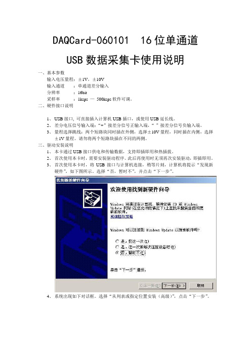
3、首次使用本卡时,将USB接口与计算机连接,稍等片刻,计算机将提示“发现新硬件”,如下图所示。
选择“否,暂时不”,并点击“下一步”。
4、系统出现如下对话框。
选择“从列表或指定位置安装(高级)”,点击“下一步”。
5、系统出现如下对话框。
选择“不要搜索。
我要自己选择安装的驱动程序”,点击下一步。
6、如出现下面的对话框,选择“通用串行总线控制器”,点击“下一步”。
7、系统出现如下对话框。
则点击“从磁盘安装”。
8、在弹出的路径对话框中选择程序安装目录下的“DAQCard-060101.Inf”文件。
点击“确定”。
9、回到6步所示对话框,此时出现提示“DAQCard(without driver)”,选中该项后,点击“下一步”。
10、系统开始安装驱动,若弹出如下对话框,选择“仍然继续”。
11、驱动安装完成,出现如下对话框,点击“完成”。
12、稍等片刻,系统再次提示安装驱动程序。
选择“否,暂时不”,点击“下一步”。
13、选择“自动安装软件”,点击“下一步”。
14、选中第二项驱动文件(如下图所示),点击“下一步”。
15、选择“仍然继续”。
16、驱动安装完成。
DAQ数据采集卡快速使用指南

DAQ数据撷取卡快速使用指南首先感您选购NI的DAQ产品,以下将简短地为您叙述快速安装与使用DAQ卡的步骤。
在安装DAQ的硬件之前,请您先确认是否安装了DAQ的驱动程序,基本上您的计算机必须有Measurement And Automation (MAX)来管理您所有的NI装置,另外您必须安装NI-DAQ 软件,目前建议安装最新的版本(您可利用光盘安装或是上网下载最新版本驱动程序.ni./support点选Drivers and Updates),新版驱动程序可支持大多数NI的DAQ卡片,包含S、E、M系列以及USB接口产品。
在安装完成NI-DAQ之后,您可以在桌面上发现有MAX应用程序,此时您可以关闭计算机,进行硬件安装,将PCI或是PCMCIA接口的DAQ卡片插入并重新开机,开机之后操作系统会自行侦测到该装置,并且自动安装驱动程序,依照对话框的带领便能顺利完成安装程序。
安装程序完成后,建议您开启MAX在Device and interface选项中会有Traditional DAQ 以及 DAQmx两个类别,那是依照您的卡片型号支持哪一种API而分类,一般而言,E系列卡片两种都支持,而M系列只支持DAQmx,S系列则不一定,在对应的Traditional DAQ或DAQmx中找到您的DAQ卡片型号,然后建议您先进行校正以及测试。
您可参考.ni./support/daq/versions确认您硬件适用的版本如何做校正与硬件测试:若需校正硬件,请于MAX中,您所安装的卡片型号上按鼠标右键选择self-calibration 即可,系统会对DAQ卡以现在温度做一次校正。
若需测试硬件,请于MAX中,您所安装的卡片型号上按鼠标右键选择Test Panels,然后选择所要测试的项目,并且依照接脚图将讯号连接妥当即可测试,建议您分别测试AI、AO、DI以及Counter。
接脚图:您可以在MAX中的DAQmx找到您所安装的卡片型号,并按鼠标右键,选择Device Pinout 便可以依照接脚图去连接相关接法,进行量测。
Pico Technology DrDAQ多功能数据采集仪说明书

多功能数据采集DrDAQ®使用灯光、声音和温度内置传感器使用标准电极测量 pH 值添加外部传感器和数字设备从一台 PC 上多达 20 个 DrDAQ 数据记录器捕捉数据通过 USB 连接和供电免费下载 PicoLog 6 和 PicoScope 6 软件免费软件开发工具包可下载示例程序免费技术支持 免费软件更新与 Windows、macOS 和 Linux 兼容传感器和指示器您的 DrDAQ 数据记录器可开箱即用;它具有内置的灯光、声音和温度传感器,以及一个您可以编程显示 1670 万种颜色其中任意一种颜色的 RGB LED 指示灯。
外部传感器插座还允许您扩展 DrDAQ 的功能。
使用内部传感器,您的 DrDAQ 可以测量湿度、氧气量、内部温度和更多值。
Pico Technology 可为您提供连接、使用以及甚至设计您自己的传感器所需要了解的一切。
不只是一款数据记录器由于 DrDAQ 的多功能性,您还可以将它用作示波器和频谱分析仪。
只需从下载和运行 PicoScope 软件,您的 DrDAQ 即可成为一个具有 100 kHz 带宽、8 位分辨率和能够测量高达 ±10 伏特电压的单通道示波器。
数字输入/输出DrDAQ 包含有 4 个数字输入/输出。
用作输入时,可为您提供更多的监控选项。
用作输出时,使您可以使用 DrDAQ 来控制外部设备。
其中两个数字输入/输出用作输入时包含有脉冲计数功能,并具有脉冲宽度调制 (PWM) 输出能力。
但这并非所有。
您的 DrDAQ 还包括一个信号发生器,可同时用作标准函数发生器和任意波形发生器 (AWG)。
AWG 功能使您可以创建自己的波形。
业余爱好者、学生或专业人士:DrDAQ 正是您所需DrDAQ 数据记录器具有每个人都需要的某些功能:无论您是在课堂中寻求有趣方式进行数据记录实验的教师、想要一种廉价数据记录方式和示波器的学生、想使用 C++ 监控实际设备输入和输出的程序员,想监控其环境的业余爱好者,还是想在实验室环境下测量 pH 值的专业人士,DrDAQ 都具有您所需的一切功能。
SmacqDAQSoftware快速使用指南
Smacq DAQ Software 快速使用指南关于Smacq DAQ SoftwareSmacq DAQ Software是Smacq为USB-3000和USB-5000系列数据采集卡开发的数据采集软件。
Smacq DAQ Software可以帮助没有编程经验的用户快速获取实验数据。
Smacq DAQ Software的设计主要是针对基础应用,对于复杂应用需要用户根据实际情况选择合适的开发环境,编程实现相关功能。
Smacq提供多种环境的开发范例和说明文档,如有需要请到自行下载或与service@取得联系。
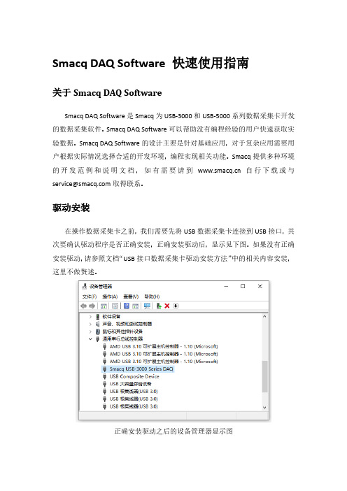
驱动安装在操作数据采集卡之前,我们需要先将USB数据采集卡连接到USB接口,其次要确认驱动程序是否正确安装,正确安装驱动后,显示见下图。
如果没有正确安装驱动,请参照文档“USB接口数据采集卡驱动安装方法”中的相关内容安装,这里不做赘述。
正确安装驱动之后的设备管理器显示图软件安装找到Smacq DAQ Softwave所在文件夹,双击运行setup.exe文件,一直下一步即可完成安装。
软件安装完成安装完成后,会在桌面创建快捷方式Smacq DAQ Softwave。
打开软件双击Smacq DAQ Software快捷方式打开软件。
打开软件后,点击Device List 按键,会在界面左侧显示连接到该电脑上的所有USB-3000和USB-5000系列数据采集卡的信息。
选择数据采集卡系列连接数据采集卡在设备选择列表中选择需要操作的采集卡,然后点击连接按键后,采集卡可以使用功能会激活。
连接数据采集卡功能说明Smacq DAQ Software有多种功能,详见下表。
YT模式采集卡连接后,点击YT按键,进入到YT模式。
YT模式是使用最多的功能,在YT模式中显示电压随时间变化的曲线。
在进行数据采集之前,需要选对采集卡进行设置。
YT模式模拟采集设置在YT模式中,点击设置进入YT-Config界面。
首先设置模拟输入的通道模式,根据硬件连接的方式进行选择,如果不清楚如果连接,可参考用户手册中3.2章节信号连接方式。
NI数据采集(DAQ)设备入门指南说明书

DAQ Getting Started GuideThis guide describes how to confirm your NI data acquisition (DAQ) device is operating properly. Install your application and driver software, then your device, using the instructions packaged with your device. Confirm Device RecognitionComplete the following steps:unch MAX by double-clicking the NI MAX icon on the desktop, or (Windows8) by clickingNI MAX from NI Launcher.2.Expand Devices and Interfaces to confirm your device is detected. If you are using a remoteRT target, expand Remote Systems, find and expand your target, and then expand Devices andInterfaces. If your device is not listed, press <F5> to refresh the configuration tree. If the device isstill not recognized, refer to /support/daqmx.For a Network DAQ device, do the following:•If the Network DAQ device is listed under Devices and Interfaces»Network Devices, right-click it and select Add Device.•If your Network DAQ device is not listed, right-click Network Devices, and select Find Network NI-DAQmx Devices. In the Add Device Manually field, type the Network DAQdevice’s host name or IP address, click the + button, and click Add Selected Devices. Yourdevice will be added under Devices and Interfaces»Network Devices.Note If your DHCP server is set up to automatically register host names, the device registers thedefault host name as cDAQ-<model number>-<serial number>, WLS-<serial number>,or ENET-<serial number>. You can find the serial number on the device. If you cannot find thehost name of that form, it may have been modified from the default to another value.If you still cannot access your Network DAQ device, click the Click here for troubleshootingtips if your device does not appear link in the Find Network NI-DAQmx Devices window orgo to /info and enter the Info Code netdaqhelp.Tip You can test NI-DAQmx applications without installing hardware by using an NI-DAQmxsimulated device. For instructions on creating NI-DAQmx simulated devices and importingNI-DAQmx simulated device configurations to physical devices, in MAX, select Help»Help Topics»NI-DAQmx»MAX Help for NI-DAQmx.3.Right-click the device and select Self-Test. When the self-test finishes, a message indicates successfulverification or if an error occurred. If an error occurs, refer to /support/ daqmx.4.For NI M and X Series PCI Express devices, right-click the device and select Self-Calibrate.A window reports the status of the calibration. Click Finish.Configure the Device SettingsSome devices, such as the NI-9233 and some USB devices, do not need properties for configuringaccessories, RTSI, topologies, or jumper settings. If you are installing only devices without configurable properties, skip to the next step. Configure each device with configurable settings that you install:1.Right-click the device name and select Configure. Be sure to click the device name under thefolder for the system (My System or Remote Systems) and NI-DAQ API in which you want tocontrol the device.For Network DAQ devices, click the device name and then the Network Settings tab to configurenetwork settings. For additional information on configuring Network DAQ devices, refer to yourdevice documentation.2.Configure the device properties.•If you are using an accessory, add the accessory information.•For IEEE 1451.4 transducer electronic data sheet (TEDS) sensors and accessories, configure the device and add the accessory as previously described. Click Scan for TEDS. To configureTEDS sensors cabled directly to a device, in MAX, right-click the device under Devices andInterfaces and select Configure TEDS.3.Click OK to accept the changes.Install Signal Conditioning or Switch DevicesIf your system includes SCXI signal conditioning modules, Signal Conditioning Components (SCC)such as SC carriers and SCC modules, terminal blocks, or switch modules, refer to the getting started guide for the product to install and configure the signal conditioning or switch hardware.Attach Sensors and Signal LinesAttach sensors and signal lines to the terminal block or accessory terminals for each installed device.You can find device terminal/pinout locations in MAX, the NI-DAQmx Help, or the devicedocumentation. In MAX, right-click the device name under Devices and Interfaces, and selectDevice Pinouts.For information about sensors, refer to /sensors. For information about IEEE 1451.4 TEDS smart sensors, refer to /teds. If you are using SignalExpress, refer to Use NI-DAQmx withYour Application Software.Run Test PanelsUse the MAX test panel as follows.1.In MAX, expand Devices and Interfaces or Devices and Interfaces»Network Devices.2.Right-click the device to test, and select Test Panels to open a test panel for the selected device.3.Click the tabs at the top and Start to test the device functions, or Help for operating instructions.4.If the test panel displays an error message, refer to /support.5.Click Close to exit the test panel.DAQ Getting Started Take an NI-DAQmx MeasurementNI-DAQmx Channels and TasksA physical channel is a terminal or pin at which you can measure or generate an analog or digital signal.A virtual channel maps a name to a physical channel and its settings, such as input terminal connections,the type of measurement or generation, and scaling information. In NI-DAQmx, virtual channels areintegral to every measurement.A task is one or more virtual channels with timing, triggering, and other properties. Conceptually, a taskrepresents a measurement or generation to perform. You can set up and save configuration information in a task and use the task in an application. Refer to the NI-DAQmx Help for complete information about channels and tasks.Use the DAQ Assistant to configure virtual channels and tasks in MAX or in your application software. Configure a Task Using the DAQ Assistant from MAXComplete the following steps to create a task using the DAQ Assistant in MAX:1.In MAX, right-click Data Neighborhood and select Create New to open the DAQ Assistant.2.In the Create New window, select NI-DAQmx Task and click Next.3.Select Acquire Signals or Generate Signals.4.Select the I/O type, such as analog input, and the measurement type, such as voltage.5.Select the physical channel(s) to use and click Next. the task and click Finish.7.Configure individual channel settings. Each physical channel you assign to a task receives a virtualchannel name. To modify the input range or other settings, select the channel. Click Details forphysical channel information. Configure the timing and triggering for your task. Click Run. Use NI-DAQmx with Your Application SoftwareThe DAQ Assistant is compatible with version 8.2 or later of LabVIEW, version 7.x or later ofLabWindows™/CVI™ or Measurement Studio, or with version 3 or later of SignalExpress.SignalExpress, an easy-to-use configuration-based tool for data logging applications, is at Start»AllPrograms»National Instruments»NI SignalExpress or (Windows8) NI Launcher.To get started with data acquisition in your application software, refer to the tutorials:Application Tutorial LocationLabVIEW Go to Help»LabVIEW Help. Next, go to Getting Started with LabVIEW»GettingStarted with DAQ»Taking an NI-DAQmx Measurement in LabVIEW.LabWindows/CVI Go to Help»Contents. Next, go to Using LabWindows/CVI»Data Acquisition»Taking anNI-DAQmx Measurement in LabWindows/CVI.Measurement Studio Go to NI Measurement Studio Help»Getting Started with the Measurement StudioClass Libraries»Measurement Studio Walkthroughs»Walkthrough: Creating aMeasurement Studio NI-DAQmx Application.SignalExpress Go to Help»Taking an NI-DAQmx Measurement in SignalExpress.© National Instruments3DAQ Getting Started GuideExamplesNI-DAQmx includes example programs to help you get started developing an application. Modifyexample code and save it in an application, or use examples to develop a new application or add example code to an existing application.To locate LabVIEW, LabWindows/CVI, Measurement Studio, Visual Basic, and ANSI C examples, go to /info and enter the Info Code daqmxexp. For additional examples, refer to .To run examples without hardware installed, use an NI-DAQmx simulated device. In MAX, selectHelp»Help Topics»NI-DAQmx»MAX Help for NI-DAQmx and search for simulated devices. TroubleshootingIf you have problems installing your software, go to /support/daqmx. For hardwaretroubleshooting, go to /support and enter your device name, or go to /kb.If you need to return your National Instruments hardware for repair or device calibration, refer to / info and enter the Info Code rdsenn to start the Return Merchandise Authorization (RMA) process.Go to /info and enter rddq8x for a complete listing of the NI-DAQmx documents and their locations.More InformationAfter you install NI-DAQmx, the NI-DAQmx software documents are accessible from Start»All Programs»National Instruments»NI-DAQ»NI-DAQmx document title or(Windows8) NI Launcher. Additional resources are online at /gettingstarted.You can access online device documentation by right-clicking your device in MAX and selecting Help»Online Device Documentation. A browser window opens to /manuals with the results of a search for relevant device documents. If you do not have Web access, documents for supported devices are included on the NI-DAQmx media.Worldwide Technical SupportFor support information, refer to /support for access to everything from troubleshooting and application development self-help resources to email and phone assistance from NI ApplicationEngineers. Visit /zone for product tutorials, example code, webcasts, and videos.Visit /services for NI Factory Installation Services, repairs, extended warranty, calibration, and other services.To ensure measurement accuracy, NI factory calibrates all applicable hardware and issues a BasicCalibration certificate, which you can get online at /calibration.Visit /training for self-paced training, eLearning virtual classrooms, interactive CDs,Certification program information, or to register for instructor-led, hands-on courses at locations around the world.For support available at the National Instruments worldwide offices, visit , or contact your local office at /contact. National Instruments corporate headquarters is located at 11500 NorthMopac Expressway, Austin, Texas, 78759-3504.DAQ Getting Started Refer to the NI Trademarks and Logo Guidelines at /trademarks for more information onNational Instruments trademarks. Other product and company names mentioned herein are trademarksor trade names of their respective companies. For patents covering National Instrumentsproducts/technology, refer to the appropriate location: Help»Patents in your software, thepatents.txt file on your media, or the National Instruments Patent Notice at /patents.You can find information about end-user license agreements (EULAs) and third-party legal notices inthe readme file for your NI product. Refer to the Export Compliance Information at /legal/export-compliance for the National Instruments global trade compliance policy and how toobtain relevant HTS codes, ECCNs, and other import/export data.© 2003–2013 National Instruments. All rights reserved.373737H-01Jul13。
VT280 便携式数据采集仪 DAQ 振动信号采集软件 使用说明书

VT280便携式数据采集仪DAQ振动信号采集软件深圳市森瑟科技发展有限公司广东省深圳市宝安区石岩街道创维创新谷5B栋8楼电话:*************网页:电邮:*****************.cn目录1. 数据采集基本知识 (2)2. 软件使用说明 (3)2.1选择文件路径 (3)2.2创建标定文件 (4)2.3高速数据采集 (4)2.4低速数据采集 (7)2.5示波+谱分析 (9)2.6转换文本格式 (10)2.7绘采集曲线图 (12)2.8绘阵列图曲线 (15)2.9绘频域曲线图 (16)1. 数据采集基本知识对于一些试验研究,需要把传感器输出的模拟电压或电流信号转换为数字量,输入到计算机进行后续分析。
要想把模拟信号转换为数字量,需要借助于模数转换,通常用“A/D”表示本仪器所配备的DAQ软件可支持多种数据采集卡、并口数据采集仪、USB数据采集仪、数字式应变仪等。
u数据采集精度数据采集设备的分辨率的高低能决定模数转换的精度,以采集设备的A/D转换分辨率为16Bits(16位)和12Bits(12位)对比,当最大量程都为±10伏时,转换精度对应关系是:模拟输入16位模数转换数字量12位模数转换数字量─────────────────────────────────+10伏32767 20480伏(对应于)0 0-10伏-32767 -2048─────────────────────────────────转化精度0.000305伏0.00488伏这时,数字量每变化1位相当于16位模拟量变化10V/32768»0.000305V;12位模拟量变化10V/4096»0.00488V。
可以看出,16位A/D转换比12位A/D精度高16倍。
u数据采集噪声任何A/D转换自身都有一定的噪声信号,当然,噪声信号越小越好,那么如何知道采集仪的噪声信号有多大呢?首先把采集仪的一个通道短接,然后通过采集程序看采集的数据的峰值,即可得到采集仪的本底噪声。
- 1、下载文档前请自行甄别文档内容的完整性,平台不提供额外的编辑、内容补充、找答案等附加服务。
- 2、"仅部分预览"的文档,不可在线预览部分如存在完整性等问题,可反馈申请退款(可完整预览的文档不适用该条件!)。
- 3、如文档侵犯您的权益,请联系客服反馈,我们会尽快为您处理(人工客服工作时间:9:00-18:30)。
DAQ数据撷取卡快速使用指南
首先感您选购NI的DAQ产品,以下将简短地为您叙述快速安装与使用DAQ卡的步骤。
在安装DAQ的硬件之前,请您先确认是否安装了DAQ的驱动程序,基本上您的计算机必须有Measurement And Automation (MAX)来管理您所有的NI装置,另外您必须安装NI-DAQ 软件,目前建议安装最新的版本(您可利用光盘安装或是上网下载最新版本驱动程序.ni./support点选Drivers and Updates),新版驱动程序可支持大多数NI的DAQ卡片,包含S、E、M系列以及USB接口产品。
在安装完成NI-DAQ之后,您可以在桌面上发现有MAX应用程序,此时您可以关闭计算机,进行硬件安装,将PCI或是PCMCIA接口的DAQ卡片插入并重新开机,开机之后操作系统会自行侦测到该装置,并且自动安装驱动程序,依照对话框的带领便能顺利完成安装程序。
安装程序完成后,建议您开启MAX在Device and interface选项中会有Traditional DAQ 以及 DAQmx两个类别,那是依照您的卡片型号支持哪一种API而分类,一般而言,E系列卡片两种都支持,而M系列只支持DAQmx,S系列则不一定,在对应的Traditional DAQ或DAQmx中找到您的DAQ卡片型号,然后建议您先进行校正以及测试。
您可参考.ni./support/daq/versions确认您硬件适用的版本
如何做校正与硬件测试:
若需校正硬件,请于MAX中,您所安装的卡片型号上按鼠标右键选择self-calibration 即可,系统会对DAQ卡以现在温度做一次校正。
若需测试硬件,请于MAX中,您所安装的卡片型号上按鼠标右键选择Test Panels,然后选择所要测试的项目,并且依照接脚图将讯号连接妥当即可测试,建议您分别测试AI、AO、DI以及Counter。
接脚图:
您可以在MAX中的DAQmx找到您所安装的卡片型号,并按鼠标右键,选择Device Pinout 便可以依照接脚图去连接相关接法,进行量测。
接线模式(Input Configuration):接线模式一般有分为Differential、RSE、NRSE三种,其中以Differential最为准确,但此模式需要一次使用掉两个channel,一般而言,选择Differential模式时,以channel 0为例,您要将讯号正极接到channel 0并将负极接到channel 8,则量测到的值便是以channel 0减掉channel 8,原则上就是正极接channel n
负极就接channel n+8。
至于RSE接线方式则是将正极连到某channel并将负极连到ground,此方式较为不准确,而且不适用于有接地的讯号量测。
NRSE则与RSE相似,除了连接正极讯号之外,您要将负极接到AISENSE,NRSE适合量测有接地讯号。
偏压电组:当您的DAQ量测值有偏移或是明显噪声时,请确认改用Differential的接线模式,如果仍然有噪声或是数值偏移,请在负极接点channel n+8处直接再连一条100K奥姆的电阻到AI GND,此电阻称为偏压电阻,偏压电阻应该可以有效改善量测精确度。
在LabVIEW中使用DAQ小帮手快速建立基本应用:
首先开启LabVIEW然后在程序区中拖曳出DAQ小帮手,将DAQ Assistant放到白色的程序区后,会出现如下画面:
接着以量测电压值的输入为例,选择Analog Input再选择Voltage,然后选择所要使用的信道,图中例是使用ai0到ai3总共四个通道作撷取,选择完毕按下Finish。
接着会出现如下画面,您可以在此设定您的取样速率(若设为100000,表示每秒取十万个数值,但现在因为有四个信道所以每个信道会分别取到25000个点,换言之,各别通道本身所取样的点与点之时间间隔为十万分之四秒),此外您可以设定所要量测的讯号大小围,建议您的围是略大于讯号极值,如此可以将量测的准确度与分辨率最佳化。
在此您也可以设定您的量测接线模式与取样动作的方式,除非您需要动用该DAQ卡片超过一半的信道,否则强烈建议您使用Differential方式,另外取样动作模式有分为撷取单一点(每执行一次程序只抓一点),有限的多点撷取(可以设定要抓多少点,程序会依照您设定的取样速度抓到您所要求的点数),以及连续撷取。
画面中以连续撷取为例,取样速率为100000,每次呈现5000个点,量测围-3到7伏特之间。
当设定完成之后,按下OK计算机会自动完成设定工作,出现如下画面:
图中淡蓝色DAQ Assistant会自动出现,但我们必须手动加上外围的循环,并且连上一个Graph让抓到的数据可以显示出来,右边就是人机接口中数据显示的画面。
DAQ小帮手也可以做计数器输出入、数字讯号输出入以及模拟输出的设定,其设定方法与AI 小异,您可以自行尝试看看。
常见问题:
1.我不是使用LabVIEW,请问要去哪里才能找到C或VB的例程序?
答:在我的计算机中,路径
C:\Program Files\National Instruments\NI-DAQ\Examples下面都有各种语言的例程序。
当然您必需先安装特定的程序语言(如VB、VC等),您才能在NI-DAQ安装过程中勾选该程序语言的例程序,安装完成后,您也才能顺立的开启特定程序语言的DAQ例。
2.为何我的DAQ装置在MAX看不到?
答:如果您的DAQ是使用USB接口的,或许它是DAQmx BASE的系统,那必须在开始程序集中的DAQmx BASE中做设定,不过现在最新版本的DAQ驱动程序也已经能够支持了,所以建议您可以下载最新版本安装,这样在MAX中就可以看到这项装置。
3.量测值不准确么办?
答:您可以先确认是否选用Differential模式(差动模式),如果已经是使用Differential模式,那么可以在讯号负极接脚处,再连接一条100K奥姆的电阻到模拟接地处,这会使量测值更稳定准确,如果还是有相同问题存在,则可以检查是否有强烈噪声在附近干扰,尤其像马达之类的高电磁场装置附近。
若您是从Sensor传感器来取得数据,您亦可考虑使用NI的SCXI(多通道)或SCC(少信道)讯号处理设备。
4.DAQ的精确度如何计算?
答:首先您要先知道您的量测需分辨率到多少,通常卡片会有多少位分辨率,如16bit 的规格,您可以把您所量测的讯号围除以2的16次方,便是您讯号的分辨率。
但请注意,分辨率是表示对于讯号变动多少DAQ卡能感测到,但是实际精确度必须依照规格书,参酌使用温度,使用多久了以及量测讯号围等等计算出来。
5.DAQmx与Traditional DAQ有何不同?
答:基本上它们都是驱动DAQ的应用程序接口,只不过DAQmx强化的效能与反应速度,并且在程序撰写时将各种不同的DAQ功能更加系统化的整合到多型的VI当中,所以显得比较单纯容易撰写 (LabVIEW7.0之前版本只支持Traditional DAQ)。
6.请问我要做数字讯号输出入,该如何做呢?
答:您可以使用DIO或是Counter,Counter能计数TTL的讯号变化,算出数字讯号的on/off切换几次,而DIO则是针对数字讯号的状态做侦测或是改变,所以他们两者都是处理数字讯号,但是功能不同。
7.我要输出特定样本(Pattern)的数字波形,请问DAQ卡做得到吗?
答:在现在的M系列卡片上是可以办到的,我们可以将AI或AO的频率指定给DO做参考,这样DO就可以依照我们给定的update rate却做某个特定pattern的输出。
8.为何我在做模拟输入时,我写两组独立的模拟输入程序去控制一卡片上不同信道或是用
两个DAQ小帮手做AI就会动作不正常,或出现错误讯息?
答:这是API的限制,因为我们大多数卡片都只有一个模拟数字转换器(ADC),所以在做撷取时,每个不同的通道是靠多任务器(multiplexer)切换来做扫描模拟数字转换,若是同时写两个AI程序,等于是对ADC下两次指令,所以有时会出现资源已被占用的错误或是动作不正常。
您必须将所有的AI信道用一组程序做控制。
网络资源:
1..ni./support/labview NI-DAQmx常见问题与解答
2.digital.ni./manuals.nsf/websearch/ADB8F1EBED9FDB6186256E630074B7A6?OpenDocu
ment&node=132100_US DAQ快速上手说明
3.ni./support/daq/versions 最新DAQ驱动程序下载。