江苏大学2012机械设计真题
江苏大学机械设计制造及其自动化专业介绍

机械设计制造及其⾃动化 培养⽬标:本专业培养具备机械设计制造基础知识与应⽤能⼒,具有机电新产品开发与管理企业所需的知识结构及潜能,也具有适应科研、教育、经贸及⾏政管理等部门⼯作或继续深造的素质和能⼒,能在机械⼯程及其⾃动化领域内从事设计制造、科技开发、应⽤研究、运⾏管理和经营销售等⽅⾯⼯作的⾼级⼯程技术⼈才。
培养特⾊:该专业是江苏省第⼀批品牌专业、第⼀批特⾊专业建设点。
本专业将通识教育与专业教育有机结合,以机械科学、电⼦技术、计算机技术、机电控制技术为主体构建学科基础课程体系,兼顾⼯程科学教育与⼯程实践训练,以培养个性健全、情操⾼尚、基础扎实、知识⾯⼴、应⽤能⼒强、具有创新精神的复合型⾼级⼯程技术⼈才。
本专业是⼀个宽⼝径专业,含有机械制造及其⾃动化、机械设计及其⾃动化2个专业⽅向,学⽣在修完公共课程后可根据个⼈特长和社会需要选修专业⽅向,接受专业⽅向的⼯程设计、专业实习及专业设计等现代机械⼯程师的基本训练,具有进⾏机械产品设计、制造及设备控制、⽣产组织管理的基本能⼒。
主要课程:⼯程图学、⼯程⼒学、机械原理及设计、电⼯电⼦学、⼯程材料及其成型基础、机械制造技术基础、控制⼯程基础、微机原理与应⽤、机电传动控制、液压与⽓压传动、机械⼯程测试技术、数控技术、机械系统设计、机械制造⾃动化、质量管理与控制、计算机辅助设计、数字化制造技术等。
深造机会:该专业所在学科在我校设有机械⼯程⼀级学科博⼠学位授权点和博⼠后流动站,有机械设计及理论、机械制造及其⾃动化、机械电⼦⼯程等3个⼆级学科博⼠点和机械制造及其⾃动化、机械电⼦⼯程、机械设计及理论等3个硕⼠点,其中机械⼯程⼀级学科为江苏省重点学科,机械制造及其⾃动化为国家重点培育学科,为学⽣的进⼀步深造提供了有利的条件,成绩优秀者可以提前免试进⼊研究⽣阶段学习。
⽬前该专业所在学科博⼠⽣导师有近20⼈,在校硕⼠研究⽣有280多⼈,博⼠研究⽣有近40⼈。
就业状况及趋势:毕业⽣可在机械、汽车、冶炼、交通运输、轻⼯、化⼯、电⼦等⾏业从事机械设计制造及其⾃动化⽅⾯的技术和管理⼯作,也可在⾼等学校、科研机构和国家机关从事教学、科研和⾏政管理⼯作。
关于《机械优化设计》教学的实施与思考

关于《机械优化设计》教学的实施与思考摘要:《机械优化设计》是机械设计制造类本科专业的专业基础课,是数学规划与计算机技术高度结合的学科。
本文论述了将机械设计类课程相结合的必要性和在实际教学中课程设计的实施与效果,并讨论了《机械优化设计》课程的重要性。
关键词:《机械优化设计》;课程设计;《机械设计》课程体系中图分类号:g642 文献标志码:a 文章编号:1674-9324(2013)08-0212-02一、国内教学现状《机械优化设计》是机械设计制造类本科专业的专业基础课,是数学规划与计算机技术高度结合的学科。
本课程通常以理论教学为主,涉及的数学知识与优化算法较多,其内容理论性强,又很抽象,不易理解,导致学生学习该课程的热情普遍不高。
江苏大学是国内较早开始《机械优化设计》课程的学校之一。
马履中等[1]在教学改革中,将教材内容不断更新、注意优化软件建设,不断更新和自编新的优化软件,注意教学手段的改革,积极推行多媒体教学及双语教学;注意收集学生的优秀作业、应用实例、优化软件。
长江大学汪建华等[2]重视对学生知识应用能力和实际操作能力的培养,以适应社会需要为目标,着重“应用”二字,以“应用”为主旨和特征构建教学内容,重视对学生的技术应用能力的培养。
教学中引入matlab优化工具箱,减少学生编程与调试的工作量,将课程教学重点放在数学模型的建立上,优化方法的选择,以及matlab优化工具箱中优化函数的使用上,使学生既学到了优化的思想与理论方法,又能够把实际决策问题用数学建模的方法转化为优化模型。
河南工业大学武照云等[3]加大实验环节的学时安排(10学时左右为宜),开发基于matlab的算法程序库,运用面向对象的程序语言visual basic进行软件开发,采用算法可视化技术。
何亚银[4]开展课堂板书、多媒体教学和网络教学相结合的授课方式,将《机械优化设计》与c语言相结合,通过c语言编程来实现相关算法。
目前国内外的机械工程教育向着复合型人才和工程应用能力培养的趋势发展,学生不仅需要有坚实的数理科学知识,同时需要工程实践方面的训练,强调理解知识、掌握学习的方法、培养独立分析与解决工程实践问题的能力。
江苏大学机械毕业设计外文翻译

江苏大学机械毕业设计电磁阀外文翻译附录Ⅰ:Magnetoelastic Torque Sensor Utilizing a Thermal Sprayed Sense-Element for Automotive Transmission ApplicationsBrian D. KilmartinSiemens VDO Automotive Corporation ABSTRACTA Magnetoelastic based Non-Contacting, Non-Compliant Torque Sensor is being developed by Siemens VDO for automotive transmission applications. Such a sensor would benefit the automotive industry by providing the feedback needed for precise computer control of transmission gear shifting under a wide range of road conditions and would also facilitate cross-platform usage of a common transmission unit.Siemens VDO has prototyped transmission torque sensors operating on the principle of Inverse- magnetostriction, also referred to as the Inverse-Joule Effect and the Villari Effect. Magnetostriction, first documented in the mid 1800’s, is a structural property of matter that defines a m aterial’s dimensional changes as a result of exposure to a magnetic field. Magnetostriction is caused when the atoms that constitute a material reorient in order to align their magnetic moments with an external magnetic field. This effect is quantified for a specific material by its saturation magnetostriction constant, which is a value that describes a material’s maximum change in length per unit length.Inverse-magnetostriction, conversely, defines changes in a material’s magnetic properties in response to applied mechanical forces. Material that is highly magnetostrictive and elastic in nature is referred to as being magnetoelastic. The premise of the Siemens VDO torque sensor design is that a magnetoelastic material can be bonded to a cylindrical shaft and magnetized in its mechanical quiescent state to create a sense- element. While under torque, principle tensile and compressive stress vectors in the form of counter- spiraling, mutually orthogonal helices develop in the shaft and are conveyed to the magnetoelastic sense-element giving rise to a measurable magnetic field change. The magnetic field deviation that arises from the magnetoelastic sense-element is directly proportional to the magnitude of the imposed torque. In effect, the magnetic field is modulated by torque. A sensitive magnetometer then translates the field strength into an analog voltage signal, thereby completing the torque-to-voltage transducer function.Critical to the success of the Siemens VDO torque sensor design is an intimate attachment of the sense- element to the torque-bearing member. Inconsistencies in the boundary between the sense-element and the torque-bearing member will result in aberrant coupling of stresses into the sense-element manifesting in performance degradation. Boundary inconsistencies can include such imperfections as voids, contaminates, lateral shearing, and localized zonesof stress pre-load. Such inhomogeneities may be inherent to an attachment method itself or may subsequently be caused by systemically rendered malformations.Thermal spray, the process where metal particles are deposited onto a substrate to form a coating, was used to address the issue of securely affixing magnetic material to a torque-bearing member. In addition to achieving the prerequisite of an intimate and secure bond, the thermal spray process can be regulated such that the deposited magnetic material is pre-loaded with the internal stresses needed to invoke the inverse- magnetostriction effect.Summarizing, the passive nature of the magnetic sense- element provides an intrinsically simple kernel for the Siemens VDO torque sensor that makes for a highly reliable and stable design. The thermal spray process adds robustness to the mechanical aspect by permitting torque excursions to an unprecedented ±2000% of full scale (per prototype validation testing of certain constructs) without the need for ancillary torque limiting protection devices. Furthermore, accuracy, repeatability, stability, low hysteresis, rotational position indifference, low cost and amenability to the high-volume manufacturing needs of the automotive marketplace are all attributes of this torque sensing technique. When coupled with a magnetometer that is grounded in well- established fluxgate technology, the resultant sensor is inherently dependable and can potentially establish a new standard for torque measuring sensors.INTRODUCTIONAs is well known, automotive transmissions are designed to alter the power transfer ratio between the engine and the drive wheels effectively optimizing engine loading. The engine thereby runs in a narrow and efficient operating band even though the vehicle travels over a wide range of speeds. For automatic transmissions, shift valves select the gear ratio based generally on the throttle position, engine vacuum and the output shaft governor valve state. With the advent of electronic sensors and computerized engine controllers, transmission shift functions have been migrating towards closed-loop operation under software processing control. Along with this progression came the realization that the transmission output torque would provide a valuable feedback parameter for shift and traction control algorithms. The measurement of output torque, however, proved elusive due to the extremely harsh operating conditions. One particular SUV application under consideration required 1% accuracy in measurements of roughly 2700 Nm with possible torque excursion of 4700 Nm; all while exposed to temperature extremes -45 to +160 o C.One method for measuring torque is to examine the physical stresses that develop in a shaft when it is subjected to an end-to-end twisting force. The principle stresses are compressive and tensile in nature and develop along the two counter-spiraling, mutually orthogonal 45 o helices. They are defined by the equation :t = Tr / JWhere T is the torque applied to the shaft, r is the shaft radius and J is the polar moment of inertia.Setting p r4/ 2 = J for a solid cylindrical shaft and r = d/2 yields:t = 16T / p dOnce again, T is the torque applied to the shaft and d is the shaft diameter.Furthermore, the degree of twist experienced by the shaft for a given torque is given by2: q = 32(LT) / (p d4G)Where L is the length of the shaft, T is the applied toque, d is the diameter of the shaft and G is the modulus of rigidity of the shaft. The modulus of rigidity defines the level of elasticity of the shaft material, thus, a lower G value would manifest in a shaft with a higher degree of twist for any given applied torque.Torque induced stresses that occur in the shaft material are transferred into an affixed magnetic coating and give rise to measurable changes in its surrounding magnetic field that are directly proportional to the magnitude of the applied torque; with the polarity of the magnetic field, i.e., north or south, governed by the direction of the applied torque. In essence, this is the premise of torque sensing by means of inverse magnetostriction.TORQUE SENSOR EMBODIMENTTo effectively invoke the inverse-magnetostriction effect, the magnetic material must be correctly pre-loaded with stress anisotropy in its quiescent state. In the case of a cylindrically shaped magnetic element, the anisotropic forces must be circumferential (i.e., tangential) in nature and can be either compressive or tensile –depending on the polarity or sign of the material’s saturation magnetostriction constant. Achieving a homogenous pre-load throughout the magnetic material is crucial if the sensor is to accurately interpret torque regardless of its rotational position within a stationary magnetometer.POSITIVE MAGNETOELASTIC DEVICESEarlier efforts to create such a torque sensing element relied on a sense element made of material with a positive saturation magnetostriction constant. This embodiment was realized with a ring-shaped magnetoelastic element made from 18% nickel-iron alloy that intrinsically requires tensile circumferential pre- loading 3 . Such a pre-load was achieved by pressing the ring onto a tapered area of the base shaft – effectively stretching it. The effect of tensile stress on the magnetic hysteresis behavior is shown in Figure 1 where the remnant inductance, B r , nearly triples. The “easy-axes” of the magnetic domains align circumferentially due to the anisotropy defined by the principal tensile stress vector. When magnetically biased, the system in effect operates as a circumferentially shorted magnet with B approaching B r and H approaching zero.NEGATIVE MAGNETOELASTIC DEVICESTo advance the state of the art, Siemens VDO Automotive has opted for a magnetoelastic element witha negative saturation magnetostriction constant. In this case, the alloy is very high in nickel content exhibiting a saturation magnetostriction, l s , in the range of -3e-5 dl/l and requires the stress pre-load to be tangentially compressive in nature. To achieve this embodiment, the magn etoelastic material that constitutes the sense element is “deposited” onto the base shaft using a high- velocity-oxygen-fuel (HVOF) thermal spray process. The coating thickness is only 0.5mm with an axial length of 25mm. The sense element material is endowed with compressive stress by means of precise control of the thermal spray process parameters. This proprietary procedure transforms a deposition process that normally confers isotropic material properties into one that renders the requisite stress anisotropy.Prototype FabricationMagnetoelastic ElementThe specification for the shaft requires the measurement of torque levels of 2700 Nm with no deleterious effects following exposures of up to 4700 Nm. Operating temperature is -45 o C to 160 o C.By c onverting from the earlier torque sensor “pressed-on ring” concept to one based on a magnetoelastic material with a negative saturation magnetostriction constant, l s , the design is advanced in several respects. Primarily, its resiliency against stress/corrosion cracking is enhanced by 1) the inherent insusceptibility of high nickel content alloys towards corrosives and 2) by the lower porosity of material in compression. This is in distinct contrast with the high iron content ring placed in tension which is vulnerable to fissuring, material creep and stress corrosion cracking which can, over time, relieve the necessary anisotropic forces causing performancedegradation.An important consequence of using the thermal spray technology is the intimate bond provided between the deposited magnetoelastic element and the base shaft. By using a thermal spray process, the boundary whereby torque induced stresses are transferred is free of such imperfections as voids, galled or furrowed material and localized stress gradients that are all characteristically associated with the pressed-on ring technique. These imperfections can induce aberrations in the magnetic field shape thereby imparting torque measurement errors relative to the rotational position of the shaft with respect to a stationary magnetometer. Furthermore, the strong bond at the interface effectively eliminates the slippage commonly associated with the interference fit of a pressed-on ring during extreme torque exposures. Any movement at this interface will manifest as a biasing of material stresses causing a zero-shift measurement error. This is not a concern when the magnetoelastic element is deposited using an HVOF thermal spray gun. Torque excursions to an unprecedented ±2000% of full scale have been successfully applied directly to prototype sensors without ancillary torque limiting protection devices.In addition, depositing the magnetoelastic element onto a rotating shaft provides an inherently mechanically balanced assembly that imposes no angular velocity (RPM) or angular acceleration limits on the system.Other thermal spray technology attributes are its amenability to high volume manufacturing environments, the robustness of the process insuring consistent reproducibility, and an overall reduction in fabrication steps –such as the elimination of machining procedures to mass-produce rings, cutting operations for precisely matching tapers on the shaft and ring, and pressing operations to install rings onto shafts.Magnetic Field ShapingContributions from the mechanical mounting tolerances of system components (e.g., bearings and bushings) can manifest as a misalignment between the centroid centerlines of the magnetometer and the magnetoelastic element. Once calibrated, any displacement in the positional relationship between these two components will alter the system’s transfer function, possibly causing the overall error to exceed specification. The sharply focused nature of the magnetic field radially emanating from the magnetoelastic element during the application of torque (see Figure 3) accentuates this effect. This error can be minimized by shaping the physical structure of the magnetoelastic element resulting in a contouring of the magnetic field to a more favorable shape. As shown in Figure 4, the magnetic field is made to be less pronounced with an hourglass shaped magneto elastic element and sensitivity to misalignment is, thus, reduced. In this example, the magneto elastic element is contoured such that the air gap between the magneto elastic element and the magnetometer is reduced when axial displacement between their centroid centerlines occurs. The expected reduction in magnetic signal strength caused by this displacement is thus compensated by the air gap reduction.Shafts can be fabricated with a variety of contoured surface adaptations and the thermal sprayed magnetoelastic element’s shape will expectedly follow suit. As is evident, a pressed-on ring manifestation of the magnetoelastic element would be incompatible with this technique. Various contours are being considered for further reducing the sensitivity to misalignment and for improving other performance parameters such as magnetic field strength and hysteresis.Cylindrical Shaft Shown with Superimposed Associated Magnetic Field (i.e., Radially Directed Flux Density)Contoured Shaft (Hourglass Shape) Shown with Superimposed Associated Magnetic Field (i.e., Radially Directed Flux Density)In Figures 3 and 4, the spatial image of the shaft is mapped using a laser displacement system and the superimposed magnetic field is mapped in 3-space with a hall cell.MagnetometerRounding out the torque sensor hardware complement is a non-contacting magnetometer that translates the magnetic signal emitted by the shaft’s sense element into an electrical signal that can be read by system-level devices. Coupling the torque signal to some interim conditioning electronics magnetically is an attractive op tion due to its “non-contacting” attribute. A signal transference scheme capable of spanning an air gap is advantageous sinceit requires no slip rings, brushes or commutators that can be affected by wear, vibration, corrosion or contaminants.The fundamental magnetometer embodiment, shown in Figure 5, is circular with the shaft passing through its center. The magnetometer encompasses the magnetoelastic element of the shaft and the shaft is allowed to freely rotate within the fixed magnetometer. Power and the output signal pass through the magnetometer’s wiring harness.Transmission Torque Sensor MagnetometerThe magnetometer actually performs several functions beyond measuring a magnetic field’s strength. These functions include magnetic signal conditioning, electrical signal conditioning, implementation of self-diagnostics, and the attenuation of magnetic and electromagnetic noise sources.The magnetic detection method chosen for the torque sensor is fluxgate magnetometry, also known as saturable-core magnetometry. This is a well-established technology that has been in use since the early 1900’s. Fluxgate magnetometers are capable of measuring small magnetic field of strengths down to about 10 -4 A/m (or 10 -6 Oe) with a high level of stability. This performance is roughly three orders of magnitude better than that achieved by Hall Effect devices. Although many fluxgate designs use separate drive and pickup coils, the torque sensor magnetometer was designed to use a single coil for both functions.Magnetic signal conditioning is accomplished by use of flux guides integral to the magnetometer. These flux guides amplify the magnetic signal radiating from the shaft’s sense element prior to detection by the fluxgates thereby improving the signal-to-noise ratio. The flux guides provide additional signal conditioning by integrating inhomogeneities in the magnetic signal relative to the shaft rotational position that might otherwise be misinterpreted as torque variations. The flux guide configuration is shown in Figure 6 and a magnetic simulation of the resulting field concentration is shown in Figure 7.Flux guides surrounding magnetoelastic elementAxial view of magnetic simulation with flux guide material’s relative DC permeability set to 50,000 (e.g., HyMu “80”)To further improve the magnetometer’s immunity to stray signals present in the ambient, common-mode rejection schemes are employed in the design of both the electronic and magnetic circuits. For example, wherever possible, differential circuitry was used in theelectronic design in order to negate common-mode noise. This practice was carried over to the magnetic design through the use of symmetrically shaped flux guides and symmetrically placed fluxgates that cancel common- mode magnetic signals that originate outside the system.Finally, to augment the electrical and magnetic common- mode rejection strategies, EMI and magnetic shielding practices were incorporated into the design to further improve the signal-to-noise ratio. Stray magnetic and electro-magnetic signals found in the ambient are prevented from reaching the fluxgates and the shaft’s magnetic torque-sensing element through the use of shielding material that encompasses these critical components.The functional diagram of Figure 8 depicts the concept of the magnetometer by showing a simplified version of the circuitry with extraneous components removed for additional clarity. An application specific integrated circuit (ASIC) contains all the circuitry necessary to perform the indicated functions.Magnetometer Functional DiagramSummarizing, the multi-function, fluxgate based magnetometer design provides the optimal platform for detecting the modulated magnetic field that emanates from the shaft’s torque-sensing magnetic element. By coupling time-proven fluxgate technology with an innovative flux guide configuration and with sophisticated electronic circuitry, the resultant magnetometer is durable, accurate, and stable and comprehensively achieves the design goals dictated by the application.CONCLUSIONThe latest developments in the magnetoelastic torque sensor that are presented here advance the current state of the technology by addressing many obstacles that have delayed itsacceptance by the automotive industry. Thermal spray deposition of the magnetoelastic element has resolved problems that have plagued earlier versions of the magnetoelastic torque sensor’s active element. The lack of integrity of the shaft/magnetoelastic element interface, stress-corrosion cracking, long term stability, inhomogeneity of magnetic properties and manufacturing processes that run counter to high volume production, are no longer hindering the introduction of magnetoelastic torque sensors into the automotive marketplace. With design goals clearly defined and an aggressive development program invariably progressing, the prospect of an automotive, magnetoelastic based non-compliant torque sensor is now more readily attainable.ACKNOWLEDGMENTSI would like to acknowledge the efforts of Ivan Garshelis who pioneered this approach to torque sensing and who had the unwavering vision to recognize this technology’s potential; and Carl Gandarillas whose scientific and analytical investigative approach has explicated much of the mystery associated with thermal sprayed magnetics. I would also like to express my gratitude to the torque sensor development team at Siemens VDO Automotive for their dedication and the extra effort that they put forth; and to Siemens VDO Automotive management for having the courage to invest in a new technology and the patience to see it through.REFERENCES1. Raymond J. Roark and Warren C. Young, Formulas for Stress and Strain, 5 th Edition, McGraw-Hill; Chapter 9, Torsion2. Stephen H.Crandall and Norman C. Dahl, An Introduction to the Mechanics of Solids, McGraw-Hill; Chapter 6, Torsion3. Ivan J. Garshelis, Magnetoelastic Devices, Inc., IEEE Transaction On Magnetics ; 0018-9464/92 V ol. 28, No. 5 September 5, 1992ADDITIONAL SOURCES1. Richard L. Carlin, Magnetochemistry; Springer-Verlag2. Rollin J. Parker, Advances In Permanent Magnetism; John Wiley & Sons3. Etienne du Tremolet de Lachhesserie, Magnetostriction Theory and Applications of Magnetostriction; CRC Press4. Richard M. Bozorth, Ferromagnetism; IEEE Press附录Ⅱ:磁力矩传感器利用一个热喷涂感知元件在汽车变速器中的应用转载自:2003年发动机电子控制布赖恩D.基尔马丁西门子威迪欧汽车电子公司摘要一个非接触式的,非兼容扭矩的传感器是由西门子VDO正在开发应用于汽车传动之中。
080301 机械设计制造及其自动化
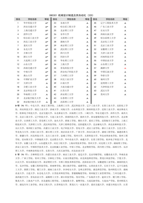
080301 机械设计制造及其自动化 (320)B+等 (96个):中北大学、南京工程学院、上海理工大学、武汉科技大学、辽宁工业大学、长春工业大学、沈阳化工学院、西安科技大学、湖北工业大学、济南大学、河海大学、山东科技大学、陕西科技大学、沈阳工业大学、南京林业大学、桂林电子科技大学、北京交通大学、东北林业大学、河南理工大学、三峡大学、华东交通大学、西华大学、南昌大学、北京工商大学、辽宁科技大学、大连工业大学、西南科技大学、扬州大学、西安建筑科技大学、南华大学、北京林业大学、江西理工大学、青岛理工大学、汕头大学、淮海工学院、烟台大学、重庆工学院、沈阳航空工业学院、上海工程技术大学、天津理工大学、武汉科技学院、天津工程师范学院、沈阳建筑大学、北京邮电大学、西北农林科技大学、长江大学、郑州轻工业学院、内蒙古工业大学、电子科技大学、青岛大学、武汉工业学院、浙江工业大学、五邑大学、华北电力大学、河南工业大学、浙江理工大学、南京农业大学、广西大学、西安石油大学、湖南工程学院、福建农林大学、新疆大学、河北科技大学、北方工业大学、盐城工学院、郑州大学、太原科技大学、华北水利水电学院、徐州工程学院、佳木斯大学、中国地质大学、北京联合大学、华中农业大学、南通大学、长春工程学院、杭州电子科技大学、北华大学、安徽工业大学、山东建筑大学、河北工程大学、上海应用技术学院、苏州大学、河北理工大学、湖南理工学院、西安工业大学、中国科学技术大学、北京机械工业学院、中原工学院、北京物资学院、四川理工学院、深圳大学、长沙理工大学、中南林业科技大学、长春大学、大庆石油学院、河北农业大学B等 (96个):吉林师范大学、内蒙古农业大学、南京工业大学、延边大学、北京印刷学院、安徽农业大学、华南农业大学、广西工学院、常州工学院、吉林化工学院、石家庄铁道学院、河北科技师范学院、黑龙江科技学院、宁夏大学、江汉大学、哈尔滨商业大学、南京财经大学、吉林工程技术师范学院、沈阳农业大学、安徽建筑工业学院、湖南科技大学、长沙学院、安徽工程科技学院、西南林学院、浙江海洋学院、成都学院、山西农业大学、石河子大学、辽宁石油化工大学、淮阴工学院、厦门大学、湖南工业大学、齐齐哈尔大学、宝鸡文理学院、湖北师范学院、徐州师范大学、湖南农业大学、大连大学、东北电力大学、江苏技术师范学院、景德镇陶瓷学院、郑州航空工业管理学院、兰州交通大学、南昌航空大学、青岛农业大学、成都理工大学、浙江科技学院、茂名学院、广东海洋大学、温州大学、厦门理工学院、集美大学、上海水产大学、河北建筑工程学院、上海海事大学、襄樊学院、大连民族学院、大连水产学院、贵州师范大学、湖北汽车工业学院、西安工程大学、江苏科技大学、黑龙江八一农垦大学、重庆交通大学、内蒙古科技大学、江苏工业学院、上海师范大学、东北农业大学、广州大学、邵阳学院、新疆农业大学、福建工程学院、合肥学院、北京建筑工程学院、唐山学院、佛山科学技术学院、临沂师范学院、黑龙江工程学院、湖南文理学院、吉林农业科技学院、攀枝花学院、吉林农业大学、中国计量学院、运城学院、上海电机学院、南阳理工学院、江西农业大学、湖南师范大学、华北科技学院、潍坊学院、甘肃农业大学、铜陵学院、东莞理工学院、安阳工学院、皖西学院、河南农业大学C等(64个):名单略080305 机械电子工程 (46)排名学校名称等级排名学校名称等级排名学校名称等级1 上海交通大学A+ 4 西南交通大学 A 7 西安交通大学 A2 浙江大学A+ 5 重庆大学 A 8 华南理工大学 A3 上海大学 A 6 北京理工大学 A 9 同济大学 A B+等 (14个):江苏大学、南京工程学院、中北大学、长安大学、西南石油大学、西华大学、武汉工程大学、苏州大学、上海理工大学、上海海事大学、江苏技术师范学院、桂林电子科技大学、浙江理工大学、辽宁工程技术大学B等 (14个):湖南文理学院、南京林业大学、黑龙江工程学院、广东技术师范学院、江苏科技大学、攀枝花学院、河北建筑工程学院、北京石油化工学院、华东交通大学、成都理工大学、西北农林科技大学、山东农业大学、常州工学院、南京师范大学C等(9个):名单略080601 电气工程及其自动化 (262)B+等 (79个):天津商业大学、石家庄经济学院、广西大学、辽宁工程技术大学、南昌大学、上海海事大学、中国农业大学、河南理工大学、长沙理工大学、北京航空航天大学、山东科技大学、南京工程学院、辽宁工业大学、兰州理工大学、内蒙古工业大学、电子科技大学、兰州交通大学、上海理工大学、云南师范大学、西安科技大学、华南农业大学、河北农业大学、浙江工商大学、中原工学院、中国民航大学、北京邮电大学、山东理工大学、安徽理工大学、广西民族大学、大连海事大学、天津理工大学、河北科技师范学院、华东理工大学、江南大学、浙江万里学院、湖北工业大学、暨南大学、安徽建筑工业学院、昆明理工大学、新疆大学、南京师范大学、南华大学、长春工业大学、哈尔滨工程大学、华北水利水电学院、南京邮电大学、湖南工程学院、黑龙江科技学院、河北工程大学、郑州轻工业学院、郑州航空工业管理学院、郑州大学、沈阳建筑大学、延边大学、大庆石油学院、华侨大学、重庆工学院、吉林大学、河北科技大学、桂林电子科技大学、中国地质大学、陕西科技大学、西南民族大学、安徽大学、石家庄铁道学院、唐山学院、湖北师范学院、浙江海洋学院、南通大学、青岛大学、北京联合大学、沈阳工程学院、山东农业大学、天津城市建设学院、天津工业大学、宝鸡文理学院、上海应用技术学院、河北建筑工程学院、西安石油大学B等 (79个):济南大学、石河子大学、贵州师范大学、河西学院、攀枝花学院、复旦大学、上海工程技术大学、安徽工业大学、巢湖学院、北京理工大学、上海电机学院、中北大学、北京建筑工程学院、江西理工大学、邵阳学院、徐州师范大学、淮阴工学院、宁波大学、浙江科技学院、华北科技学院、青海大学、北方工业大学、常州工学院、厦门理工学院、成都理工大学、南开大学、山西农业大学、西北民族大学、茂名学院、北京工商大学、福建农林大学、西南石油大学、长安大学、吉林建筑工程学院、许昌学院、中国计量学院、四川师范大学、中国科学技术大学、福建工程学院、宁夏大学、湖北民族学院、五邑大学、佛山科学技术学院、鲁东大学、广州大学、华南热带农业大学、山东工商学院、山东轻工业学院、长春大学、榆林学院、重庆邮电大学、天津科技大学、黄石理工学院、青岛农业大学、北京石油化工学院、云南农业大学、河北师范大学、武汉工业学院、嘉兴学院、广东海洋大学、长沙学院、重庆交通大学、青岛理工大学、大连交通大学、盐城工学院、肇庆学院、西北农林科技大学、红河学院、大理学院、浙江工业大学、台州学院、韩山师范学院、南京工业大学、青岛科技大学、西安建筑科技大学、太原科技大学、内蒙古农业大学、黑龙江工程学院、山东交通学院C等(52个):名单略080602 自动化 (263)B+等 (79个):吉林大学、内蒙古大学、郑州大学、河海大学、中国农业大学、重庆邮电大学、内蒙古工业大学、中山大学、辽宁石油化工大学、北华大学、桂林电子科技大学、武汉大学、北京联合大学、南京工程学院、中国民航大学、西南科技大学、昆明理工大学、华北电力大学、杭州电子科技大学、江苏大学、青岛理工大学、天津理工大学、沈阳建筑大学、青岛科技大学、安徽工业大学、长春工业大学、沈阳化工学院、北京邮电大学、西安科技大学、辽宁工业大学、桂林工学院、南京邮电大学、济南大学、安徽理工大学、黑龙江大学、广西大学、贵州大学、安徽工程科技学院、大连海事大学、北方工业大学、天津工业大学、上海海事大学、中国石油大学、河北工业大学、河南大学、安徽大学、江南大学、河南科技大学、湘潭大学、上海电力学院、山东轻工业学院、西南交通大学、南昌大学、深圳大学、湖北工业大学、长安大学、河南理工大学、青岛大学、中国海洋大学、北京信息工程学院、河北科技大学、郑州轻工业学院、西南石油大学、北京林业大学、南华大学、长春理工大学、天津科技大学、黑龙江科技学院、四川理工学院、江西理工大学、新疆大学、湖南文理学院、大连交通大学、成都信息工程学院、吉林化工学院、南昌航空大学、中国计量学院、南京农业大学、北京机械工业学院B等 (78个):沈阳航空工业学院、南京师范大学、天津工程师范学院、山东理工大学、华东交通大学、五邑大学、南京工业大学、浙江理工大学、上海理工大学、中国地质大学、西南大学、北京工商大学、三峡大学、上海工程技术大学、湖南工程学院、江苏科技大学、江苏工业学院、长江大学、河北工程大学、西安工程大学、福州大学、南通大学、西安建筑科技大学、北京石油化工学院、吉林农业大学、西安邮电学院、长春工程学院、攀枝花学院、宁波大学、浙江科技学院、内蒙古科技大学、华侨大学、南京大学、华南农业大学、大庆石油学院、湖南科技大学、西安石油大学、佳木斯大学、湖北汽车工业学院、山西大学、大连民族学院、扬州大学、北京印刷学院、烟台大学、徐州师范大学、华北科技学院、长沙理工大学、中原工学院、安徽建筑工业学院、铜陵学院、襄樊学院、中南民族大学、沈阳大学、安阳工学院、曲阜师范大学、西安工业大学、通化师范学院、齐齐哈尔大学、南京林业大学、广西工学院、武汉工程大学、安庆师范学院、太原科技大学、东北林业大学、合肥学院、成都学院、盐城工学院、淮海工学院、重庆工学院、辽宁科技学院、石家庄铁道学院、河北理工大学、武汉工业学院、中南林业科技大学、潍坊学院、大连大学、长春大学、北京服装学院C等(53个):名单略。
江苏大学课后答案考试试题全免费下载
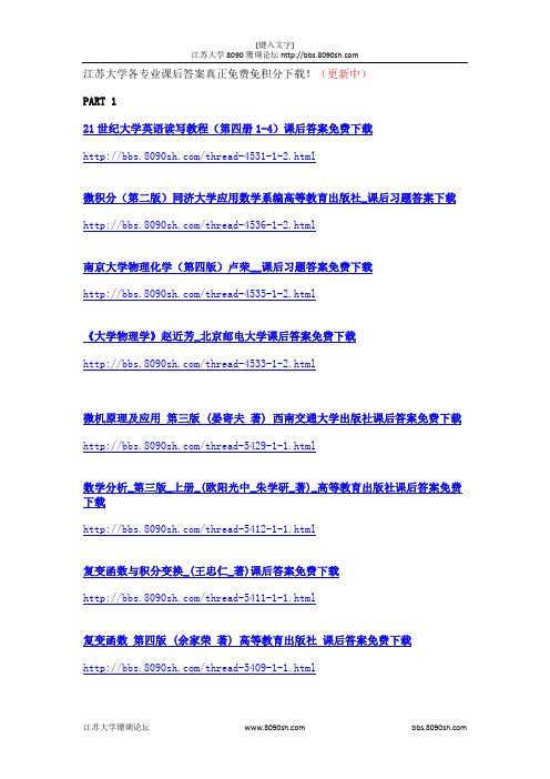
江苏大学各专业课后答案真正免费免积分下载!(更新中)PART 121世纪大学英语读写教程(第四册1-4)课后答案免费下载/thread-4531-1-2.html微积分(第二版)同济大学应用数学系编高等教育出版社_课后习题答案下载/thread-4536-1-2.html南京大学物理化学(第四版)卢荣__课后习题答案免费下载/thread-4535-1-2.html《大学物理学》赵近芳_北京邮电大学课后答案免费下载/thread-4533-1-2.html微机原理及应用第三版 (晏寄夫著) 西南交通大学出版社课后答案免费下载/thread-5429-1-1.html数学分析_第三版_上册_(欧阳光中_朱学研_著)_高等教育出版社课后答案免费下载/thread-5412-1-1.html复变函数与积分变换_(王忠仁_著)课后答案免费下载/thread-5411-1-1.html复变函数第四版 (余家荣著) 高等教育出版社课后答案免费下载/thread-5409-1-1.html线性代数 (惠淑荣张京李修清著) 东北大学出版社8090珊瑚论坛课后答案免费下载/thread-5406-1-1.html数理统计第二版 (赵选民徐伟师义民秦超英著) 科学出版社课后答案免费下载/thread-5404-1-1.html随机过程 (汪荣鑫著) 西安交通大学出版社课后答案免费下载/thread-5402-1-1.html当代世界经济与政治第三版,人民大学出版社课后答案下载/thread-5401-1-1.html全新版大学英语第三册综合教程练习课后答案下载/thread-5398-1-1.html线性代数简明教程第二版(陈维新著课后答案免费下载/thread-5397-1-1.html思想道德修养与法律基础 2010版 (罗国杰夏伟东著) 高等教育出版社课后答案下载/thread-5396-1-1.html统计学高教第三版课后习题答案8090珊瑚论坛.pdf/thread-5395-1-1.html概率论与数理统计教程_(茆诗松_程依明_濮晓龙_著)_高等教育出版社课后答案免费下载/thread-5381-1-1.html线性代数简明教程第二版(陈维新著)8090珊瑚论坛.pdf/thread-5380-1-1.html微分几何初步 (陈维桓著) 北京大学出版社课后答案免费下载/thread-5379-1-2.html复变函数习题全解及导学课后答案免费下载.pdf/thread-5378-1-2.html临床医学英语 (高艳陈迎著) 中国海洋大学出版社课后答案.zip/thread-5353-1-2.html普通物理学第三册第五版 (程守洙胡盘新著) 高等教育出版社/thread-5352-1-2.html马克思主义基本原理概论第四版 (本书编写组著) 高等教育出版社免费下载/thread-5351-1-2.html电磁场与电磁波第二版 (周克定翻译著著)课后答案免费下载/thread-5350-1-2.html大学语文第九版 (徐中玉齐森华著) 华东师范大学出版社/thread-5348-1-2.html人大版《会计学基础》课后答案免费免积分下载/thread-4438-1-2.html机电传动控制邓星钟第四版课后答案免费免积分下载/thread-4436-1-2.html现代控制理论第3版刘豹唐万生课后全部答案机械工业出版社免费免积分下载地址/thread-4382-1-2.html《模拟电子技术基础》(第四版)童诗白,华成英_高等教育出版社_课后习题答案下载/thread-4432-1-2.html《自动控制原理》胡寿松_第四版科学出版社课后答案免费免积分下载/thread-4435-1-2.html工程力学_静力学与材料力学_(单辉祖_谢传锋_著)_高等教育出版社_课后答案免费下载/thread-4442-1-3.html工程材料及成形技术_林建榕_高教版课后习题参考答案免费免积分下载/thread-4440-1-3.html《电机及拖动基础》顾绳谷_第四版_机械工业出版社_课后答案免费免积分下载/thread-4434-1-3.html《电工学》秦曾煌第六版上下册课后答案免费免积分下载/thread-4430-1-3.html《数字信号处理(第三版)西安电子科技大学出版社(丁玉美)课后答案/thread-4429-1-3.html《通信原理教程》_樊昌信_最新版电子工业出版社课后答案免费免积分下载/thread-4426-1-3.html《信号与系统》第二版课后答案完整版_郑君里免费免积分下载/thread-4424-1-3.html最全数据结构课后习题答案(耿国华版[1]免费免积分下载/thread-4423-1-3.htmlMATLAB程序设计与应用_刘卫国主编_高等教育出版社课后答案免费免积分下载/thread-4422-1-3.html电磁场与电磁波_第四版_(谢处方_饶克谨_著)课后答案免费免积分下载/thread-4421-1-3.html传感器原理及工程应用_第三版__课后答案免费免积分下载电工学_第七版_秦曾煌_课后习题答案免费免积分下载/thread-4389-1-3.html电力电子技术王兆安第五版课后习题答案免费免积分下载/thread-4387-1-3.html电路_第五版_邱关源_高等教育出版社_课后答案详细版免费免积分下载/thread-4386-1-3.html电路分析_第二版_课后答案_胡翔骏_高等教育出版社免费免积分下载/thread-4385-1-3.html离散数学课后答案(清华版)免费免积分下载/thread-4384-1-3.html通信原理_(周炯盘_著)_北京邮电大学出版社_课后答案免费免积分下载/thread-4383-1-3.html信息论与编码-曹雪虹-课后习题答案免费免积分下载地址/thread-4381-1-3.html移动通信_第三版_(郭梯云__李建东_著)课后答案免费免积分下载/thread-4380-1-3.html自动控制理论(第二版)夏德钤_课后答案免费免积分下载《新视野大学英语读写教程(第二版)》【第一册】课后答案免费下载,免积分下载/thread-4335-1-4.html《线性代数》(同济第四版)课后习题答案(完整版)免费免积分下载/thread-4334-1-4.html《概率论与数理统计教程》课后答案(完整版,魏宗舒版)免费免积分下载/thread-4331-1-4.html曼昆宏观经济学课后答案(第五版)免费免积分下载/thread-4330-1-4.html《中国近代史纲要》完整课后习题答案免费下载/thread-4316-1-4.html机械设计_濮良贵、纪名刚_第八版_第五章课后习题答案免费下载/thread-4313-1-4.html21世纪大学英语读写教程第一册.课后答案免费下载免积分下载/thread-4312-1-4.html21世纪大学英语读写教程(第一二三册)课后翻译答案免费下载/thread-4310-1-4.html大学英语精读第三册课后答案免费免积分下载c语言程序设计第三版谭浩强课后答案免费免积分下载/thread-4307-1-4.html复变函数论第三版高教出版社课后习题答案免费下载/thread-4028-1-4.html专为江苏大学学生整理,真正免积分,只有花几秒钟注册一下就可以任意下载海量资源了~~收藏哦~~留着有用。
专业名称机械设计制造及其自动化
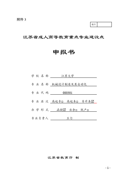
附件3
江苏省成人高等教育重点专业建设点
申报书
学校名称江苏大学
专业名称机械设计制造及其自动化
专业代码080301
专业层次高起专□高起本□专升本
办学形式函授 业余□ 脱产□
专业负责人王匀
江苏省教育厅制
填表说明
1.本表限用A4纸双面打印。
2.封面上层次、形式各只能选择一项并请在相应层次、形式方框中画√。
专业名称、代码根据《普通高等学校本科专业目录》(教高﹝2012﹞9号)和《普通高等学校高等职业教育(专科)专业目录》(教职成﹝2015﹞10号)填报。
3.本表统计范围仅限申报专业,填写内容应真实,统计数据应准确,有关佐证材料应齐全。
4.申报学校应严格审核,并对所填内容的真实性负责。
5.本表中填写内容可以根据情况进行扩充;有关统计内容的截止时间为2016年8月31日。
一、专业基本情况
二、建设目标
三、建设基础
四、研究成果
1.近5年有关成人教学管理研究论文、论著情况
注:请附有关证明材料,下同。
2.近5年成人教学管理立项研究情况
4、近5年成教教材建设及获奖情况
五、支撑保障
21
六、审核意见
22。
江苏大学毕业设计(论文)答辩记录 - 京江
学生姓名 刘子健 学号 4111101042
减速箱体左端面 3*M5 孔攻螺纹专用机床设计 郭娟
职 称
பைடு நூலகம்
2、攻螺纹时螺纹孔的螺距是怎么样确定的? 答:攻螺纹机构上有个靠模机构,靠模机构里有一根带螺纹的靠模螺杆,和一个带 螺纹的靠模螺母,这两个带螺纹的螺杆和螺母的螺距和加工孔的螺距相同,当靠模机构 运作时,靠模螺杆每推进一个螺距,就是丝锥攻进螺纹孔的一个螺距,从而保证螺纹孔 的螺距精度。
h 2 ——工件上孔的最低位置 h4 ——侧底座高度
h1 ——最低主轴高度
h3 ——滑台与滑座总高
答辩小组组长签字: 年 月 日
3、机床联系尺寸图的装料高度是如何确定的? 答:设计组合机床时,装料高度可视具体情况在 H=850-1060 之间取,并主要考虑 与车间运送工件的滚道高度相适应。根据公式 h2 H h4 h3 h1 0.5 得出:H=891.5mm,在 850-1060 之间,所以取装料高度为 891.5mm
江苏大学(京江学院)本科毕业设计(论文)答辩记录
京江学院 学院 机械设计 专业 课题名称 指导教师姓名 答辩摘要:
1、攻螺纹加工示意图和钻孔加工示意图有哪些不同的地方? 答:钻孔加工示意图需要有一个钻模板,上面安装导套,进行导向作用,保证加工 孔的位置精度;而攻螺纹加工示意图是没有钻模板的,不需要通过钻模板来保证加工螺 纹孔的精度。而是通过攻螺纹装置本身的靠模机构来保证。
实习指导书 基础工程训练(Ⅱ)
实习指导书基础工程训练(Ⅱ)班级学号姓名江苏大学基础工程训练中心说明1.本实习指导书由曾艳明、马鹏飞、张应龙编写,马伟民审核。
2.每名学生实习结束后完成指导书中的习题。
江苏大学基础工程训练中心二○一五年九月修订目录导论 (1)车工模块一车床简述及台阶轴加工 (2)车工模块二刀具、切削用量、锥度加工 (4)车工模块三车床常用附件及孔加工 (6)车工模块四螺纹车削加工 (8)车工模块五数控车床基本操作 (9)车工模块六数控车削加工程序的编制 (10)车工模块七数控车削零件加工 (11)钳工模块一概述、锯削、锉削加工 (13)钳工模块二根据图纸划线加工 (14)钳工模块三钻孔和螺纹加工 (15)钳工模块四装配 (16)钳工模块五磨削加工、齿轮加工及镗削加工 (17)铣工模块一铣床概述及铣四方 (18)铣工模块二铣床附件及铣削六角螺母 (19)铣工模块三铣削加工范围及铣凹凸配合 (20)铣工模块四数控铣床概述 (21)铣工模块五数控铣削编程、铣凸台二 (22)特种加工模块一初识电火花加工 (24)特种加工模块二线切割工程训练 (25)铸造模块一铸造概述和手工整模造型 (26)铸造模块二石膏模创新制作与铸造合金熔炼 (28)铸造模块三特种铸造 (29)锻工模块一锻压概述与机锻羊角锤方坯 (30)锻工模块二手工自由锻羊角锤 (31)锻工模块三板料冲压 (32)焊接模块一手工电弧焊 (33)焊接模块二气焊 (34)焊接模块三其它焊接方法 (36)热处理模块一淬火与回火 (37)热处理模块二正火与退火 (38)热处理模块三表面热处理 (39)电工模块一安全用电 (40)电工模块二相异步电动机接触器点动控制线路 (41)电工模块三三相异步电动机行程控制正反转电路 (42)电子模块一常用电子元器件 (43)电子模块二手工焊接 (44)电子模块三实习件装配调试 (45)电子模块四表面贴装技术应用 (46)实习小结........................................................................................................... 错误!未定义书签。
江苏大学机械工程学院历年分数线汇总
江苏大学机械工程学院历年复试情况汇总2012年1、机械工程学术型一志愿复试分数线:(1)满足条件:①总分310、②政治50、③英语50或者CET-6通过、④数学80、⑤专业课100,可参加机械工程学术型硕士研究生复试。
2、机械工程专业型一志愿复试分数线:(1)机械工程及密切相关专业本科毕业,满足条件:①总分310、②政治50、③英语50或者CET-6通过、④数学80、⑤专业课100,可参加机械工程专业型硕士研究生复试。
3、光学工程学术型、仪器科学与技术总分310分,英语、政治45分,数学一、专业课75分。
2013年1)机械工程专业型、学术型①【总分310、政治50、英语50、数学80、专业课100】,或者②【总分320、政治50、英语50、数学75、专业课100】。
2)机械制造及其自动化专业复试门槛分数线上线生源充裕,达到机械工程(专业型、学术型)硕士研究生复试门槛分数线,并且总分≥350的考生。
3)机械设计及理论专业复试门槛分数线上线生源充裕,达到机械工程(专业型、学术型)硕士研究生复试门槛分数线,并且总分≥330的考生。
4)机械电子工程学术型、机械工程专业型复试资格条件为:达到机械工程(专业型、学术型)硕士研究生复试门槛分数线的考生。
5)3、光学工程(学术型、专业型)一志愿复试分数线:总分300、政治45、英语45、数学60、专业课806)4、仪器科学与技术学术型、仪器仪表工程专业型一志愿复试分数线:总分300、政治45、英语45、数学60、专业课802014年机械工程学术型招生76名,其中推免生10名;一志愿复试分数线:总分295分、单科成绩满足国家线要求;实际参加复试人数70人,涮掉4人,其中录取者初试最高分383,最低分295.机械工程专业型招生73名,其中推免生7名;一志愿复试分数线:总分305分、单科成绩满足国家线要求;实际参加复试人数76人,涮掉10人左右,其中录取者初试最高分390,最低分306.注:有需要*理论力学*以及*机械原理*资料*的考生请和*学长*联系,扣*扣:142*8832*821(保证物美价廉)2015年机械工程学术型招生76名,其中推免生6名;一志愿复试分数线:总分300分、英语和政治44分,数学和专业课75分;实际参加复试人数79人,涮掉9人左右,其中录取者初试最高分394,最低分300.机械工程专业型招生74名,无推免生;一志愿复试分数线:总分305分、英语和政治45分,数学和专业课75分;实际参加复试人数90人,涮掉16人左右,其中录取者初试最高分409,最低分305.。
基于PLC的机械手控制设计
基于PLC的机械手控制设计本文主要介绍了基于PLC的机械手控制设计。
随着现代制造技术的不断发展,机械手在工业生产中的应用越来越广泛,机械手控制系统的控制方式也在不断更新迭代。
本文提出了一种基于PLC控制机械手的新型控制方案。
1.机械手的基本原理机械手是一种基于电气、电子、机械、气动等多种技术相结合的智能机器人,其通过伺服电机、减速器、编码器等组件,实现了对各类物品的精准抓取、搬运、插入、安装等功能。
机械手控制系统一般由PLC、传感器、驱动模块等组成。
2.PLC的基本原理PLC(可编程控制器)是一种基于逻辑控制的自动化控制系统,主要由CPU、存储器、输入/输出模块、通信模块等组成。
通过编写PLC程序,可以实现对各类自动化设备的控制和管理。
(1)PLC编程设计程序编写是PLC系统中最重要的部分,这里以三轴机械手为例,可以将机械手运动分解成若干个基本的运动要素:横向、竖向、旋转。
通过PLC程序让机械手根据场景要求完成一系列的运动需求。
(2)PLC输入输出配置PLC输入/输出配置是设计控制系统时非常重要的部分。
基于PLC的机械手控制系统,输入/输出模块可以通过编程实现对机械手的控制。
需要根据机械手控制系统对应的型号、规格、要求等,对PLC输入/输出模块进行配置。
(3)硬件选型与安装本文实现的基于PLC的机械手控制,需要选择适合的硬件设备完成组装,并进行布线和安装。
(4)系统调试和优化在完成硬件组装和软件编程后,需要对整个机械手控制系统进行调试和优化。
主要是通过测试各项运动功能是否符合预期要求、能否按时完成任务等。
(1)控制精度高:PLC的控制精度高,支持对伺服电机进行精准控制,可以保证机械手运动精度。
(2)程序编写灵活:PLC编程可以根据生产实际需求,灵活定制机械手的各个运动要素及相应动作。
(3)易于维护:PLC控制系统将整个机械手控制系统设备集成在一起,为运维和维护带来便利。
(4)可实现远程监控:PLC控制系统可以通过网络连接实现远程监控,实时获取机械手的运行状态和运动参数。
- 1、下载文档前请自行甄别文档内容的完整性,平台不提供额外的编辑、内容补充、找答案等附加服务。
- 2、"仅部分预览"的文档,不可在线预览部分如存在完整性等问题,可反馈申请退款(可完整预览的文档不适用该条件!)。
- 3、如文档侵犯您的权益,请联系客服反馈,我们会尽快为您处理(人工客服工作时间:9:00-18:30)。
第1页,共6页
机密★启用前
江苏大学2012年硕士研究生入学考试试题
科目代码: 805 科目名称: 机械设计
考生注意:答案必须写在答题纸上,写在试卷、草稿纸上无效! 需用计算器
一. 填空题(1分×10=10分)
1.齿轮传动设计时,硬齿面闭式传动通常先按 设计公式确定齿轮参数,然后验
算轮齿面接触疲劳强度。
2.有一普通圆柱蜗杆传动,已知蜗杆头数Z1=1,蜗杆轮齿螺旋线方向为右旋,其分度圆柱上
导程角g=5042'38'',蜗轮齿数Z2=45,模数mt=8mm,压力角at=200,传动中心距a=220mm,
蜗杆直径系数q= ,蜗轮螺旋角b= 。
3.带传动设计中,应使小带轮直径d≥dmin,这是因为 。
4.滑动轴承的承载量系数Cp将随着偏心率χ的增大而 ,最小油膜厚度hmin将随着偏心
率χ的增大而 。
5.链轮的转速越高,节距p ,齿数越少,则链传动的动载荷就越大。
6.如需在同一轴段安装一对半圆键时,应将它们布置在 。
7.角接触球轴承承受轴向载荷的能力取决于 。
8.单向规律性不稳定变应力的疲劳强度计算是根据________________进行计算的。
二. 选择题(2分×15=30分)
1.在直齿圆柱齿轮设计中,若中心距保持不变,而将模数m增大,则可以 。
A.提高齿面接触强度 B.提高轮齿的弯曲强度
C.弯曲与接触强度均可提高 D.弯曲与接触强度均不变
2.在润滑良好的条件下,为提高蜗杆传动的啮合效率,可采用的方法为 。
A.减小齿面滑动速度υs B. 减少蜗杆头数Z1
C.增加蜗杆头数Z1 D. 增大蜗杆直径系数q
3.套筒滚子链传动中,大链轮的齿数Z2不能过大,若过大则会造成 。
A.链传动的动载荷增大 B.传递的功率减小
C.容易发生“脱链”、“跳齿”现象 D.链条上应力的循环次数增加
第2页,共6页
4.在滑动轴承材料中,通常只用作双金属轴瓦的表层材料的是 。
A.铸铁 B.巴氏合金
C.铸造锡磷青铜 D.铸造黄铜
5. 对不完全液体润滑滑动轴承,验算压强 p≤[p]的目的是控制滑动轴承产生 。
A.过度磨损 B.点蚀
C.胶合 D.压溃
6.某滚动轴承支承应用于温度较高,跨距较大的场合,该轴系结构应该是 。
A.一支点双向固定,另一端支点游动 B.双支点各单向固定
C. 两端游动支承 D.浮动支承
7.在蜗杆传动中,对于滑动速度v>4m/s的重要传动,蜗轮齿圈的材料常用 。
A.HT200 B.ZCuSn10P1
C.45号钢调质 D.18CrMnTi渗碳淬火
8.已知某轴上的最大弯矩M=200N·m,扭矩T=150N·m,该轴为频繁双向运转启动,则计算该
轴弯矩(当量弯矩)Mca约为 N·m 。
A.350 B.219 C.250 D.205
9.某零件的σ
s=500MPa,σ-1=220MPa,工作应力σm=300MPa,σa
=100MPa,应力满足r=c变化,
工作点位于塑性安全区,则该零件的安全系数S为 。
A.1.78 B.5.0 C.1.25 D.1.67
10.两圆柱体沿母线相压,载荷为F时,最大接触应力为
H
s
,若载荷增大到2F时,最大接触
应力变为 。
A.1.26Hs B.1.41Hs
C.1.59Hs D.2Hs
11.点、线接触的零件在变应力作用下最常见的失效形式为 。
A.磨粒磨损 B.表面压溃
C.疲劳点蚀 D.塑性变形
12.通常钢轴存在一个危险的共振区,为避免轴在共振区工作,可以采用下列哪种措施 。
A.改用强度更高的材料 B.采用表面硬化处
C.整体淬火 D.改变轴的直径
第3页,共6页
13. 要绘制零件极限应力的简化线图时,所必需的已知数据有 。
A. s-1 s0 Ks
sj B.-1sKss
ssj
C. s-1 sS Ks D.
-10s
s
sssj
14.齿轮设计加工时,常对轮齿进行齿顶修缘的目的是 。
A.提高轮齿的弯曲强度 B.改善轴向载荷分布不均匀
C.减小动载系数 D.使齿轮装配方便
15.牙嵌式离合器的下列优点中,错误的叙述是 。
A.传递转矩较大 B.结构紧凑
C.接合时平稳,冲击较小 D.接合比较可靠
三.简答题(30分)
1.工程设计中,为何经常使一对软齿面啮合传动的两齿轮的齿面有一定的硬度差值?两齿轮面
的硬度差值在多大范围内合适?
2. 根据液体动压润滑的一维雷诺方程式: 306()/pVhhhxh¶=-¶,指出形成能够承受外载荷的
液体动压油膜的基本条件。
3.试简述如何提高普通螺栓联接的疲劳强度。
4. 试分析说明套筒滚子链传动时瞬时传动比不稳定的原因,在什么特殊条件下可使瞬时传动比
恒定不变?
5.一对相啮合的标准直齿圆柱齿轮传动,有关参数和许用值如表,试分析比较哪个齿轮的弯曲
强度低?哪个齿轮的接触强度低?
齿数Z 模数m(mm) 齿宽b(mm)
YFa YSa
[σ]F MPa [σ]H MPa
小齿轮Z
1
20 2 45 2.8 2.2 490 570
大齿轮Z
2
50 2 40 2.4 2.3 400 470
第4页,共6页
四.如图所示为二级斜齿圆柱齿轮减速器和一对开式锥齿轮所组成的传动系统,已知动力由轴I
输入,转动方向如图示,试(在答题纸上重新画图解答):(15分)
(1)为使轴II和轴III的轴向力尽可能小,试合理确定减速器中各斜齿轮1、2、3、4的轮
齿旋向;
(2)标出各传动件的回转方向;
(3)分析出各对齿轮在啮合处的受力情况,画出Ft、Fa和Fr的方向。
五.某B型号普通v带传动,已知主动带轮基准直径D1=180mm,从动带轮基准直径D2=630mm,
传动中心距a=1600mm,主动轮转速n=1450r/min,装置采用带的根数Z=4,V带与带轮表面当量
摩擦系数fv=0.4,V带的弹性模量E=200MPa,当传递的最大功率P=41.5KW时:
(1)计算临界状态时,单根带工作时紧边拉力F1、松边拉力F2、带传动的有效拉力Fec;
(2)定性画出各应力沿带长方向的分布图;(在答题纸上重画)
(3) 分析V带的最大应力σmax的位置。
(4)验算带传动的包角α。
(注:e=2.718 ,B型V带截面尺寸参数:截面积A=143mm2,顶宽b=17mm,节宽bp=14.0mm,
高度h=11.0mm,V型楔角φ=400。V带轮槽角θ=380,单位长度质量q=0.18kg/mm。)(15分)
第5页,共6页
六.一钢制压力容器,已知其内径D=280mm,容器与盖子用16个M16(d
1
=13.835mm)的钢制
普通螺栓连接,螺栓的许用应力[σ]=300MPa,为保证气密性要求,残余预紧力F
1
=1.4F (F为
单个螺栓连接轴向工作载荷)。求:(15分)
1)若接合面处分别用铜皮石棉垫片(相对刚度为0.8)或金属垫片(相对刚度为0.2),则拧紧螺
栓时所需的预紧力F0各为多少?
2)容器所能承受的最大单位工作应力p为多少?
3)用受力变形线图,定性地说明1)中两种情况螺栓的预紧力及疲劳强度的变化情况。
七.轴上装有一直齿锥齿轮2和一斜齿圆柱齿轮3。轮2是从动轮,(设力集中作用于E点)、轮
3是主动轮(设力集中作用于D点)。在A、B两处各用一个角接触球轴承7208AC支承。转速
n=900r/min,转动方向如图所示。设齿轮各分力的大小为:圆周为Ft2=2000N,Ft3=4000N;
径向力Fr2=200N,Fr3=1500N;轴向力Fa2=700N,Fa3=1000N。(20分)
1.试计算轴承A和轴承B的支承反力;
2.要求轴承寿命为Lh′=11000h,试计算二轴承寿命是否足够?(取动载荷系数
p
f
=1.2,
温度系数
t
f
=1.0)。
(已知7208AC轴承的
35.2
rCkN=,024.5Nr
Ck=
)
轴承类型 派生轴向力Fd eFFra£ eFFra> 判别系数
e
X Y X Y
7208AC 0.68Fr 1 0 0.41 0.87 0.68
第6页,共6页
八.指出图中轴系结构的8处错误,并简要说明其不合理的原因。(注:不考虑轴承的润滑方式,
倒角和圆角忽略不计。)(在答题纸上画出对应的正确的结构图,并用序号表示出改正之处,说
明需要改正的理由。)(15分)