
UPS通讯协议
INFO项的ASCII码字节数为18,即LENID = 0000 0001 0010。
D11D10D9D8+D7D6D5D4+D3D2D1D0 = 0000 + 0001 + 0010 = 0011,模16余数为0011H,0011H 取反加1就是1101H,即LCHKSUM为1101H。可得:
LENGTH为 1101 0000 0001 0010,即D012H。
1.概述
XY0200 V1.20
第 3 页 共 16 页
本文规定了Hipulse优化(HIPULSE U)系列UPS与后台监控软件的通讯协议。本文以电总协议为 基本依据,并增加许多自定义的命令幀和数据,来完成后台对UPS监控的通讯要求。
2.监控内容
2.1 模拟量数据
见下文表格
2.2 开关量数据
见下文表格
2.1 模拟量数据 ................................................................. 3 2.2 开关量数据 ................................................................. 3 2.3 告警量数据 ................................................................. 3 2.4 系统设置参数 ............................................................... 3 3.物理接口 ......................................................................... 3 3.1 串行通讯口 ................................................................. 3 3.2 信息传输方式 ............................................................... 3 3.3 数据传输速率 ............................................................... 3 3.4 通讯方式 ................................................................... 3 4.信息类型及协议的基本格式 ......................................................... 3 4.1 信息类型 ................................................................... 3 4.2 协议的基本格式 ............................................................. 3 4.3 数据格式 ................................................................... 4
(7EH)
2 VER
通讯协议版本号
3 ADR
设备地址描述(1-254,0、255保留)
4 CID1
ቤተ መጻሕፍቲ ባይዱ
控制标识码(UPS模块标识码为AAH)
5 CID2
命令信息:控制标识码(数据活动作类型描述)
相应信息:返回码RTN(见返回码表4.2.2)
6 LENGTH INFO字节长度(包括LENID和LCHKSUM),数据格式见4.3
序号 1 2 3
4
5
6
7
8
9
字节数 1 1 1
1
1
2
X
2
1
格式 SOI VER ADR CID1 CID2 LENGTH INFO CHKSUM EOI
基本格式的注解见表4.2.1、4.2.2。
XY0200 V1.20
第 4 页 共 16 页
表4.2.1
序号 符号
表示意义
备注
1 SOI
起始标志位(START OF INFORMATION)
4.3.1 基本数据格式 ........................................................................................................... 4 4.3.2 LENGTH数据格式 .................................................................................................... 4 4.3.3 CHKSUM数据格式 ................................................................................................... 5 4.3.4 INFO数据格式........................................................................................................... 5 5. 编码表 .......................................................................... 6 5.1 编码分配及分类 ............................................................. 6 6. 后台通信协议 .................................................................... 8 6.1 说明 ....................................................................... 8 6.2 获取系统模拟量量化数据 ..................................................... 8 6.2.1 获取系统模拟量量化数据(浮点数,电总标准模拟量) ......................................... 8 6.2.2 获取自定义模拟量量化数据1(浮点数,厂家扩展模拟量1) .................................. 9 6.2.3 获取自定义模拟量量化数据2(浮点数,厂家扩展模拟量2) .................................. 9 6.2.4 获取自定义模拟量量化数据3(浮点数,厂家扩展模拟量3) ................................ 10 6.3 获取开关输入状态 .......................................................... 11 6.4 获取告警状态 .............................................................. 12 6.5 获取协议版本号 ............................................................ 14 6.6 获取设备厂家信息 .......................................................... 14 6.7 获取设备地址 .............................................................. 15 6.8 获取并机系统各机的设备地址 ................................................ 16
LENGTH共2个字节,由LENID和LCHKSUM组成,LENID表示INFO项的ASCII码字节数,当 LENID=0时,INFO为空,即无该项。LENGTH传输中先传高字节,再传低字节,分四个ASCII码传 送。
校验码的计算:D11D10D9D8+D7D6D5D4+D3D2D1D0,求和后模16的余数取反加1。例如:
2.3 告警量数据
见下文表格
2.4 系统设置参数
见下文表格
3.物理接口
3.1 串行通讯口
采用RS232/RS485。
3.2 信息传输方式
为异步方式,起始位1位,数据位8位,停止位1位,无校验。
3.3 数据传输速率
2400/4800/9600bps
3.4 通讯方式
在局站内的监控系统为分布结构。监控站后台与UPS并联系统的通讯也为主从方式,监控站后 台是上位机,UPS并联系统是下位机。
CID2=4BH,传输时先传送34H,再传送42H两个字节。
4.3.2 LENGTH数据格式
XY0200 V1.20
第 5 页 共 16 页
LENGTH的数据格式如下表所示:
高字节
低字节
校验码LCHKSUM
LENID(表示INFO的传送中ASCII码字节数)
D15 D14 D13 D12 D11 D10 D9 D8 D7 D6 D5 D4 D3 D2 D1 D0
XY0200 V1.20
第 1 页 共 16 页
HIPULSE U系列
后台通讯协议
艾默生网络能源有限公司
XY0200 V1.20
第 2 页 共 16 页
1.概述 ............................................................................. 3 2.监控内容 ......................................................................... 3
台达UPS协议范文
台达UPS协议范文台达UPS通讯协议说明一.硬件说明。
1.通讯波特率2400bit/s.8位数据位,1位停止位,无校验。
二.协议说明。
1.协议数据格式数据头ID号命令类型数据长度数据内容1字节2字节1字节3字节128字节(最大)说明数据头必须是“~”,转换成ASCII码是7E ID号必须是00,转换成ASCII码是3030命令类型PUPS连接到主机命令,(主机-------→UPS)S设置UPS的数据命令,(主机-----→UPS)DUPS数据返回命令,(UPS------→主机)数据长度这里的数据长度指的是数据内容的字节个数。
用3位的ASCII码表示。
数据内容实际就是主机发给UPS的命令数据。
用ASCII码表示。
读取UPS额定电压输入电参数信息(RAT命令)PC机发送7e303050303033524154说明7e数据包头,3030ID号。
50命令类型,“P”。
303033数据长度;是指数据内容的数据长度。
“003”。
524154数据内容;就是命令;“RAT”。
UPS返回数据7E3030443037303232303B3530303B3232303B3530303B31313030303B373730303B333B3135363B3237363B3B3B3B3B303B3237343B3437303B35 33303B3439353B3435303B3535303B353035说明7E数据头。
3030ID号,44命令类型,“D”。
303730数据长度,070,说明数据区有70个字节的数据。
323230UPS输入额定电压,ASCII字符220V,交流。
3B表示一个实数与另一个实数间的分隔符,ASCII字符“;”。
353030UPS输入额定频率,计算公式500*0.1=50HZ。
3B表示一个实数与另一个实数间的分隔符,ASCII字符“;”。
31表示电池的充电状态;0表示电池浮充电状态。
1表示电池均充状态。
冠军CPT2020-UPS通讯协议 081106
NV:ห้องสมุดไป่ตู้ups 版本号
长度都小于10个汉字
注B:
通信方式:RS232 UPS接口: 9D母座
波特率:2400bps,8位数据,1位停止,无校验位 UPS.2脚(TX) -------> PC.2脚(RX) UPS.3脚(RX) <------PC.3脚(TX) UPS.5脚(GND) <-------> PC.5脚(GND)
UPS通讯协议(内部)
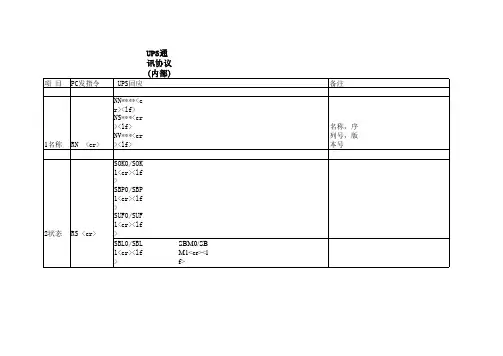
项 目 1名称 2状态 3数据 PC发指令 RN <cr> UPS回应 NN****<cr><lf> NS***<cr><lf> NV***<cr><lf> 备注 名称,序列号,版本号
RS <cr> RD <cr>
SOK0/SOK1<cr><lf> SBP0/SBP1<cr><lf> SUF0/SUF1<cr><lf> SBL0/SBL1<cr><lf> SBM0/SBM1<cr><lf> DVIA0000.00<cr><lf> DVIB0000.00<cr><lf>DVIC0000.00<cr><lf> DVOA0000.00<cr><lf> DVOB0000.00<cr><lf> DVOC0000.00<cr><lf> DLOA0000.00<cr><lf> DLOB0000.00<cr><lf> DLOC0000.00<cr><lf> DTMP0000.00<cr><lf> DHZF0000.00<cr><lf> DVBT0000.00<cr><lf> DTMB0000.00<cr><lf> SUF0/SUF1 SBP0:逆变 SBP1:旁路 NS: ups 序列号 SBL0/SBL1 SUF0:市电供电 SUF1:市电掉电
无线UPS通讯协议转换器转modbus 协议
钣金 101.1×80.4×25.5mm(不含天线与电气连接器)
工作环境
-10~60℃;5%RH~95%RH(非结露)
存储条件
-25~85℃
图表 1- 2 FZ150 技术参数表
3
FZ150 无线 UPS 通讯协议转换器模块用户手 V1.1
2 设备安装与调试
4
FZ150 无线 UPS 通讯协议转换器模块用户手 V1.1
II
FZ150 无线 UPS 通讯协议转换器模块用户手 V1.1
1 理解您的产品
1
FZ150 无线 UPS 通讯协议转换器模块用户手 V1.1
1.1 产品概述
UPS 电源品牌众多,型号各异,通信协议也各不相同,导致用户很难对 UPS 进行 集中监控。方竹电子推出的 FZ150 UPS 通讯协议转换器支持各种型号的 UPS,实 时监控 UPS 工作状态,并提供标准的 MODBUS 通讯协议接口,从而可以实现多 台 UPS 的集中监控,并可以方便地集成到各种动力环境监控系统中。
FZ150 无线 UPS 通讯协议转换器 用户手册 V1.0
杭州方竹电子科技有限公司
公司简介
杭州方竹电子科技有限公司坐落于杭州国家高新技术产业开 发区,专注于无线物联网产品的研发、生产和销售。
方竹电子提供各种无线物联网的终端产品,包括无线网关、无 线 IO 数采模块、无线温湿度模块、无线数传模块、无线分体空调 控制器等;结合我们的远程监控服务平台,提供各领域的无线监 控系统解决方案,包括无线能耗监控、无线安防监控、无线机房 监控、无线环境监测、无线农业监控、无线智能家居、无线工业 控制等。
4 运行注意事项...........................................................................................................................18 4.1 故障说明.......................................................................................................................19
正昌UPS RS232 接口协议(中文)

POWLEADING[电源先锋] UPS RS232接口通讯协议(译自厂家英文版资料)深圳市正昌时代电源系统有限公司1. 简介本文件规定了UPS制造厂家用来设计和执行UPS串口通讯的标准协议。
2. 通用的UPS参数定义注:Length长度定义为UPS发送给主机的字节数,UPS发送的字节数可以小于最大字节数。
Length长度仅适用于表示串-型式的变量。
Range范围定义为UPS发送给主机的最小和最大整数值。
整数值可以用“0”填补,但并不是必需的。
Range范围仅适用于表示整数-型式的变量。
在某些情况下,计算机只接受定义好的一组整数值,这组整数值将在现场描述中被指定。
2.1 身份识别参数组ID Group2.2 蓄电池参数组Battery Group2.3 输入参数组Input Group2.4 输出参数组Output Group2.5 旁路参数组Bypass Group2.6 告警信息组Alarm Group2.7 测试参数组Test Group2.8 控制参数组Control Group2.9 配置设置参数组Configuration Group2.10 波特率2.11 ID 号码分配3. 通讯3.1 运行参数波特率-2400 (默认值–可以用 UBR命令修改)数据位数-8停止位数-1奇偶性-无3.2 信息格式3.2.1 起始字符信息的起始字符是一个单字节数据,起始字符是漏字符( ^ )。
3.2.2 信息类型信息类型是一个单字节数据,必须是下表中的一个:0 - 命令被拒绝(从UPS到计算机主机)1 - 命令被接受(从UPS到计算机主机)P - Poll 命令(从计算机主机到UPS)S - Set命令(从计算机主机到UPS)* -主发数据(从UPS到计算机主机)D - 回传数据(从UPS到计算机主机)3.2.3 数据长度数据长度是指通过的数据的字节数。
3.2.4 数据所有数据都是用逗号隔开的。
参数必须符合3.3.1节和3.3.4节的规则规定,如果某个参数值是现在不需要或不合适用的,在该参数的位置应该放一个不带数据的逗号来表示。
台达UPS通讯协议说明

台达UPS通讯协议说明一.硬件说明。
1.通讯波特率:2400 bit/s. 8位数据位,1位停止位,无校验。
二.协议说明。
说明:数据头:必须是“~”,转换成ASCII码是7EID号:必须是00,转换成ASCII码是30 30命令类型:P:UPS连接到主机命令,(主机-------→UPS)S:设置UPS的数据命令,(主机-----→UPS)D:UPS数据返回命令,(UPS------→主机)数据长度:这里的数据长度指的是数据内容的字节个数。
用3位的ASCII码表示。
数据内容:实际就是主机发给UPS的命令数据。
用ASCII码表示。
读取UPS额定电压输入电参数信息:(RAT命令)PC机发送:7e 30 3050 30 30 3352 41 54说明:7e:数据包头,30 30:ID号。
50:命令类型,“P”。
30 30 33:数据长度;是指数据内容的数据长度。
“003”。
52 41 54:数据内容;就是命令;“RAT”。
UPS返回数据:7E 30 304430 37 30 32 32 30 3B 35 30 30 3B 32 32 30 3B 35 30 30 3B 31 31 30 3030 3B 37 37 30 30 3B 33 3B 31 35 36 3B 32 37 36 3B 3B 3B 3B 3B 30 3B 32 37 34 3B34 37 30 3B 35 33 30 3B 34 39 35 3B 34 35 30 3B 35 35 30 3B 35 30 35说明:7E:数据头。
30 30:ID号,44:命令类型,“D”。
30 37 30:数据长度,070,说明数据区有70个字节的数据。
32 32 30:UPS输入额定电压,ASCII字符:220V,交流。
3B:表示一个实数与另一个实数间的分隔符,ASCII字符“;”。
35 30 30:UPS输入额定频率,计算公式:500*0.1=50HZ。
EA990系列±240VDC UPS MODbus通讯协议_U
秘密
文件版本 生效日期 软件部
V1.1 2011.11
序号 1 2
版本 Ver 1.0 Ver 1.1
修改内容
修改时间
备注
确定基本的电气量 修改 04 功能代码
2012-4-6 2012-09-01
2011 年 11 月实施
本文件版权属广东易事特电源股份有限公司所有,违权必究
目 录
一、协议相关说明 ....................................................................................................................................... 1 1、协议简介 ................................................................................................................................................................... 1 2、接口方式 ................................................................................................................................................................... 1 3、协议格式 ................................................................................................................................................................... 1 3.1 RTU 模式的帧格式 ........................................................................................................................ 1 3.2 ASCII 模式的帧格式 ...................................................................................................................... 2 4、响应信息分类 .......................................................................................................................................................... 3 5、功能代码 ................................................................................................ห้องสมุดไป่ตู้.................................................................. 5 二、寄存器列表............................................................................................................................................ 6 1. 读输入寄存器(功能码 0X04) ......................................................................................................................... 6 2. 读离散量(功能码 0X02) .................................................................................................................................. 8 3. 预置寄存器列表(功能码 0X06,0X10) ................................................................................................... 12 三、通信内容 .............................................................................................................................................. 14 1、读输入寄存器(功能码 0X04) ..................................................................................................................... 14 2、读离散量(功能码 0X02)............................................................................................................................... 15 3、预置寄存器(功能码 0X06,0X10) ............................................................................................................... 16 附录 A LRC/CRC 校验 .......................................................................................................................... 17 LRC 纵向冗余校验 .................................................................................................................................................... 17 CRC 循环冗余校验 .................................................................................................................................................... 17 附录 B 高低位字节表................................................................................................................................ 18 高位字节表 .................................................................................................................................................................... 18 低位字节表 .................................................................................................................................................................... 18
UPS通讯协议
UPS:C1-C2K协议1.UPS状态查询:Computer : Q1<cr>UPS: (MMM.M NNN.N PPP.P QQQ RR.R S.SS TT.T b7b6b5b4b3b2b1b0<cr>MMM.M 输入电压NNN.N 发生故障时的输入电压PPP.P 输出电压QQQ 负载RR.R 输入频率S.SS 电池电压TT.T 温度UPS状态信息: b7b6b5b4b3b2b1b02.故障信息查询:Computer: DF<cr>UPS: (KK PPP FF.F OOO EE.E LLL CCC PPP NNN BB.B TT.T <b7b6b5b4b3b2b1b0>KK ---故障类型,如下FF.F ----故障时频率值OOO---故障时输出电压值EE.E---故障时输出频率值LLL---故障时输出负载值CCC---故障时输出电流值PPP ----故障时正BUS电压NNN ----故障时负BUS电压BBB.B ---故障时电池电压值TT.T ---故障时机内温度值<b7b6b5b4b3b2b1b0> --状态标识UPSComputer: MD<cr>UPS: C1k, 700,V3.01,220,220,3,12.0,11.5,13.8<cr> UPS 几个参数控制:PEX使能下表的功能PDX禁止下表的功能常用:PEO 有旁路PDO(PF)取消旁路CF60 QF电池测试命令T 测试10秒TL 测试到电池低CT 取消测试. 修改RS232波特率命令:CB24 修改波特率为2400bpsCB48 修改波特率为4800bpsCB96 修改波特率为9600bps蜂鸣器的控制命令Q打开和关闭蜂鸣器。
UPS 厂商,型号,版本的修改在RS232.asm 文件最后部分修改即可。
找到如下表:I_1K_TAB:DB '#ZhuHai ATA UPS ataC1K V3.01 *' 上表含义如下,厂商名,型号,版本。
山特3C3 UPS RS232 通讯协议
QQQ is maximum of W% or VA%. VA% is a percent of maximum VA. W% is a percent of maximum real power.
UPS Status:b7b6b5b4b3b2b1b0The same of Q2UPS status :
Temperature:
TT.T Tis an integer number ranging from 0 to 9. The unit is degree of centigrade.
UPS Status:
<b7b6b5b4b3b2b1b0>.Where <bn> is a binary number „0“ or „1“.
Stop Byte: <cr>
Shutdown command :
Computer:S<n><cr>
UPS:Shut UPS output off in <n> minutes.
The UPS output will be off in <n> minutes, even if the utility is present.
Output Voltage:
PPP.PP is an integer number 0 to 9. The Unit is Volt.
Three Phases will represent Phase R-S-T in sequence
Output Current:
QQQQQQ is a percent of maximum current , not an absolute value.
线路UPS通讯协议
JBUS ProtocolUPS MASTERYSDocumento N°IS0356Riferimento : _______Rev. N°00del19/02/09Pag. 1 di 44Elaborazione Verifica eapprovazioneEmissioneEnte Resp.le DAM – Motterle A. ATS – Bonollo T. ING – Zenere C. FirmaData 19/02/2009 19/02/2009 19/02/2009 IndexLevel 1: JBUS TABLE (2)Overview (2)JBUS Database (2)Alarms and States Database (2)States (3)Extended states (4)Alarms (5)Remote Commands (6)Standard Commands (6)Extended Commands (7)Level 2: JBUS TABLE (10)Overview (10)Alarms and States Database (10)Alarms (11)Standard alarms (11)Wrong configuration in the Parallel System (A20) (15)Advanced MODULE alarms (26)Other Advanced alarms (30)States (31)Standard states (31)Extended states (39)Advanced MODULE states (42)Pag. 2 di 44 Level 1: JBUS TABLEOverviewJBUS DatabaseThis document describes the SOCOMEC UPS protocol, adopted to communicate with all communication products, like Supervisor, Network communication, etc...This protocol will be implemented in the SOCOMEC UPS equipment, in order to use the same driver for all products. This document describe the specific implementation of MASTERYS UPS.Each SOCOMEC UPS product has a "Database" for the protocol JBUS that containing all the information. This information is divided into the following topics and each one is located in a predefined address of memory.STATES (Sxxx)ALARMS (Axxx)MEASUREMENTS (Mxxx)CONFIGURATIONS (Txxx)DATE and TIMECOMMANDS (Cxxx)The log coding is the same for all equipment, also the date and time format.Alarms and States DatabaseThe states and alarms are defined in the following way:Standard:these are coded information with the same name and meaning in all SOCOMEC UPS products.Extended:these are dedicated information that are different depending on the range of equipment.Alarms States NotesA00÷A15 S00÷S15A16÷A31 S16÷S31A32÷A47 S32÷S47 StandardA48÷A63 S48÷S63A64÷A79 S64÷S79A80÷A95 S80÷S95 ExtendedA96÷A111 S96÷S111 Axxx÷Axxx and Sxxx÷Sxxx is represented by 16bit variable; each bit corresponds to analarm/state.Advanced:these information are not included in the JBUS protocol, but they are used to manage the logic of the product. These variables may be generate alarms/states used in the standard protocol.Pag. 3 di 44StatesIn the following table there is the list of standard JBUS protocol’s states.Address base: 0x1020Range UPS Name DescriptionMod Sys BC8-40MC10-80 GP10-40 MC120GP120EMS00 Input Mains present (Mains OK) •••••S01 Inverter ON •••••S02 Rectifier ON •••••S03 Load on Inverter •••••S04 Load on Mains/Load on By-Pass •••••S05 Load on Battery/Battery Discharging •••••S06 Remote command disabled•••••S07 ECO/MODE ON •••••S08 UPS in Standby mode •••••S09 Buzzer ON ••••••S10 Battery Test in progress •••••S11 Battery Test programmed •••••S12 Battery Test in stand-by •••••S13 Battery Test supported (1=test possible) •••••S14 Battery Test failed •••••S15 Battery near end of Back-up (Low battery) •••••S16 Battery discharged/Battery end •••••S17 Battery OK •••••S18 Auto test in progressS19 Auto test in stand-byS20 Auto test supported (1 = test possible)S21 Auto test failedS22 Auto test OKS23 Inverter synchronised with Mains •••••S24 Boost ONS25 RESERVEDS26 Auxiliary mains OK •••••S27 Battery charger ON •••••S28 Auxiliary input frequency out of tolerance •••••S29 Scheduling ON/OFF disabled •••••S30 UPS on parallel system ••••••S31 Battery extension presentS32 Module 1 in parallel present •••••S33 Module 2 in parallel present •••••S34 Module 3 in parallel present •••••S35 Module 4 in parallel present •••••S36 Module 5 in parallel present •••••Pag. 4 di 44Range UPS Name DescriptionMod Sys BC8-40MC10-80 GP10-40 MC120GP120EMS37 Module 6 in parallel present •••••S38 External state 1S39 External state 2S40 External state 3S41 External state 4S42 The command control table is managed •••••S43 Power Share capability available •••••S44 E-Service Enabled •••••S45 Automatic E-Service report •••••S46 Operating on generator set •••••S47 RESERVEDS48 Maintenance mode active •••••S49 First maintenance period •••••S50 ÷S63FREEExtended statesIn the following table there is the list of extended JBUS protocol’s states.Address base: 0x1024Range UPSName DescriptionMod Sys BC8-40MC10-80 GP10-40 MC120GP120EMS64 Equalizing charge ON •••••S65 External Syncro ref ACSS66 Inverter Contactor ClosedS67 Bypass Contactor ClosedS68 Manual Bypass ClosedS69 Remote manual bypass closedS70 Output Breaker Closed •MAS MC60-80 MAS MC-GP120S71 Output Breaker bus bar oneS72 Output Breaker bus bar twoS73 Output unit coupledS74 Energy saver •••••S75 Mains Contactor switch on generator setinputS76 Always On mode activeS77 Battery Positive Test Alarm •••••S78 Battery Negative Test Alarm •••••S79 Conditions not OK at last Battery Test •••••S80 Minimum Battery Condition Pre-alarm ••S81 Minimum Battery Condition alarm ••Pag. 5 di 44AlarmsIn the following table there is the list of JBUS protocol’s alarms.Address base: 0x1040Range UPS Name DescriptionMod Sys BC8-40MC10-80 GP10-40 MC120GP120EMA00 Alarm present (OR of all UPS alarms) •••••A01 Battery failure/Battery anomaly/Batteryfuse open•••••A02 UPS overload •••••A03 Output voltage out of toleranceA04 Digital power supply fault (Vcc) •••••A05 Input voltage out of toleranceA06 Auxiliary mains out of tolerance •••••A07 Inside over-temperature alarm (OR of alltemperature sensors)•••••A08 Manual By-pass closed •••••A09 Short-circuit detection on UPS outputA10 Battery charger failure •••••A11 Inverter over-currentA12 Excessive Inverter distortionA13 Precharge voltage out of tolerance •••••A14 BOOST output voltage too low •••••A15 BOOST output voltage too high •••••A16 Battery voltage too high •••••A17 Improper condition of use •••••A18 Overload timeout blocking Inverter •••••A19 Microprocessor control system failure ••••••A20 Configuration data map corrupted ••••••A21 PLL FaultA22 Input mains general alarm •••••A23 Rectifier general alarm •••••A24 BOOST general alarmA25 Inverter general alarm •••••A26 Battery charger general alarm •••••A27 Output voltage over limitsA28 Output voltage under limitsA29 By-pass general alarm •••••A30 UPS stopped for overload •••••A31 Imminent Stop •••••A32 Module 1 in parallel general alarm •••••A33 Module 2 in parallel general alarm •••••A34 Module 3 in parallel general alarm •••••A35 Module 4 in parallel general alarm •••••Pag. 6 di 44Range UPS Name DescriptionMod Sys BC8-40MC10-80 GP10-40 MC120GP120EMA36 Module 5 in parallel general alarm •••••A37 Module 6 in parallel general alarm •••••A38 External Alarm 1 ••••••A39 External Alarm 2 ••••••A40 External Alarm 3 ••••••A41 External Alarm 4 ••••••A42 E-Service General Alarm •••••A43 Redundancy lost •••••A44 Maintenance alarm •••••A45 Transfer locked alarmA46 Transfer Blocked in bypass alarm •••••A47 Battery room alarm •••••A48 Manual bypass alarmA49 Battery discharged •••••A50 Insufficient resources •••••A51 Option board general alarm •••••A52 Rectifier fault •••••A53 Boost faultA54 Inverter fault •••••A55 Parallel fault •••••A56 Generator set general alarm •••••A57 Generator set fault •••••A58 Emergency STOP ••••••A59 Battery circuit open •••••A60 Fan fault •••••A61 Phase detection fault •••••Remote CommandsStandard CommandsIn the following table there are the "standard" commands stored in the Historical Events.All these commands are enabled by an EEP Parameter (= ENABLED):Parametro EEprom Descrizione Assist : Sezione “All Parameters”UPS Main Configuration ParametersRemote_Cmd Remote commands UPS Configuration Be careful: the “Standard Commands” in the Maintenance SW are different between if you are directly connected to Module or to System.Pag. 7 di 44 Address base: 0x15B0Name DescriptionNotesMod SysCMX00 Reset all commandsCMX01 Alarms Reset ••Reset all the active alarms CMX02 UPS OFF •Execute the “Stop Procedure” CMX03 ECO MODE enable ••Set the ECO-MODE CMX04 ECO MODE disable ••Reset the ECO-MODE (InverterON)CMX05 Stand-by Mode enableCMX06 Stand-by Mode (UPS ON) disableCMX07 Buzzer enable (only basic panel) ••Enable the buzzer logic control CMX08 Buzzer off (only basic panel) ••Switch off the buzzer temporarily(up to next event)CMX12 UPS Historical (log file) reset •Reset all the events saved in theHistorical Log before CMX13 Mimic panel led test ••CMX14 Buzzer disable •Disable the buzzer logic control CMX15 Power share plugs immediate ON •Not usedCMX16 Immediate Battery Test •Execute the manual Battery test CMX17 UPS ON •Execute the “Start Procedure”Extended CommandsThe following table describes the "extended" commands from SYSTEM.Address base: 0x15D7Name Description NotesGenericCMX01 Alarms Reset Reset all the active alarmsCMX03 ECO MODE enable Set the ECO-MODECMX04 ECO MODE disable Reset the ECO-MODE (Inverter ON) CMX07 Buzzer Enable Disable the buzzer logic controlCMX09 Buzzer Disable Enable the buzzer logic controlCMX14 Test Led Execute the test led of synopticCMX16 Power Share plug1 On Force ON the Power Share Plug1CMX17 Power Share plug2 On Force ON the Power Share Plug2CMX18 Power Share plug3 On Force ON the Power Share Plug3CMX19 Power Share plug1 Off Force OFF the Power Share Plug1CMX20 Power Share plug2 Off Force OFF the Power Share Plug2CMX21 Power Share plug3 Off Force OFF the Power Share Plug3CMX22 Maintenance service ON Set the UPS on “Maintenance Mode” (S48) CMX23 Maintenance service OFF Set the UPS on “Normal Mode”CMX24 Immediate Stop Forced It’s carried out by synoptic (keeping on pressedthe key ENTER for 4 seconds). In the HL, it issaved together CMX33Pag. 8 di 44 Name Description NotesSynopticCMX32 Start Procedure Execute the “Start Procedure”CMX33 Stop Procedure Execute the “Stop Procedure”CMX34 Statistics Reset Reset all the events saved in the Statistic Menu[Assist SW->Advanced->Monitorings] CMX35 Switch on Battery (ADC energy contact) Forced the Load on Battery due to input3 “ADCenergy contact” (A41 = ON)CMX36 Battery Forming ON Active the “Battery Forming charge” (only withOPEN_VENTED / NI-CD Battery setting) CMX37 Immediate Battery test Execute the manual Battery testCMX38 Maintenance Reject Prevent the indication of maintenancemanagement for the next monthCMX39 Switch off Battery (ADC energy contact) Return from simulation of the ADC input forswitching the UPS on BatteryCMX40 Energy saver mode enable Active the Energy saver logic (parallel unit) CMX41 Energy saver mode disable Disable the Energy saver logic (parallel unit)CMX42 Set to 1 the JBUS Slave number (afterrestart) Set the JBUS Slave number of Adv. Mimic panelto 1LanCMX48 Lan HW Reset HW Reset of Lan (RST_UBICOM)CMX49 Lan Set Default value Reset to default valueCMX50 Lan Jbus Tunneling Enable It enables the functionality of the connectionJBUS Tunnelling via networkCMX51 Lan Jbus Tunneling Disable This command is opposed to CMX50CMX52 Lan Firmware Download Enable It enables the functionality of up-grading FW fromweb pageCMX53 Lan Firmware Download Disable This command is opposed to CMX52CMX54 Lan Force Modem DialOut It forces a dial out via ModemCMX55 Lan restart SW SW Reset of LanCMX56 Lan DHCP Enable It enables the automatic acquisition of IP address CMX57 Lan DHCP Disable This command is opposed to CMX56CMX58 Send UCB date&time to Lan Send the Date&Time from UCB to LanATE/CIMCMX64 ATE mode Enable Not used in Adv. Mimic panelCMX65 ATE mode Disable Not used in Adv. Mimic panelCMX66 History-Log Reset Cancel all event stored in the History Log CMX67 All HW Reset Send an HW reset to Adv. Mimic panel CMX68 ADC custom logic default value The ADC custom logic strings are set to defaultvalueCMX69 Disable maintenance alarm management The “maintenance logic” is disabledThe “maintenance hours registered” parametersis set to 2 hoursCMX70 Start a new maintenance alarmsequence The “maintenance hours registered” parametersis set to 10004 hoursCMX71 Initialize maintenance alarm to default The “maintenance hours registered” parametersis set to default value (0 hour)Pag. 9 di 44Name Description NotesCMX72 Reset impr. use counters level2 (A17) In the Assist->Standard->Configuration menu,the counter T26 (Output/Load), T27(Mains/ByPass), T28 (Battery) and T29(Temperature) are resetCMX73 Reset UPS ON counter (T30 and T31) In the Assist->Standard->Configuration menu,the counter T30 (UPS ON hours) and T31 (UPSon Battery hours) are resetCMX74 Reset enviroment LOG counter Reset all the events saved in the Log countersMenu [Assist SW->Advanced->Monitorings]CMX75 Set code4comm="ENTERED" in all cannode The “code4com” has been entered and the icon alarm is disappear on the mimic panelCMX76 Exclude parallel bus control Exclude parallel bus control (used to replace amodule)CMX77 Set parallel bus control in normal mode Set parallel bus control in normal mode (used atthe end of replacement)DebugCMX80 Debug ram Cleaning Reset all the debug variablesMenu [Assist SW->Advanced->RAM debug] CMX81 DE Precharge ON Not usedCMX82 DE battery ON Not usedCMX83 DE Rectifier ON Not usedCMX84 DE Inverter ON Not usedOptionCMX96 Emergency Shut Down Simulate the ADC input for the EmergencyShutdown (switch off Inverter, By-Pass andRectifier)CMX97 Set bypass GenSet threshold The UPS is supplied from GenSet (S46).The UPS logic extends the thresholds of ByPass CMX98 Return in normal mode The UPS returns in Normal Mode.This command is opposed to CMX97 CMX99 ADC outputs ON/OFF This command sets ON/OFF the 4 ADC outputs.Repeating the command, the 4 outputs switch onand viceversaCMX100 ADC back to default logic This command resets the CMX99 and the ADClogic comes back to original stateCMX101 Force ON A42/Back to A42 logic This command sets ON/OFF the A42 alarm (e-service general alarm).Repeating the command, the alarm appears andviceversaPag. 10 di 44 Level 2: JBUS TABLEOverviewThis document describes the SOCOMEC UPS protocol, adopted to communicate with all communication products, like Supervisor, Network communication, etc...This protocol will be implemented in the SOCOMEC UPS equipment, in order to use the same driver for all products. This document describe the specific implementation of MASTERYS UPS.Each SOCOMEC UPS product has a "Database" for the protocol JBUS that containing all the information. This information is divided into the following topics and each one is located in a predefined address of memory.STATES (Sxxx)ALARMS (Axxx)MEASUREMENTS (Mxxx)CONFIGURATIONS (Txxx)DATE and TIMECOMMANDS (Cxxx)The log coding is the same for all equipment, also the date and time format.Alarms and States DatabaseThe states and alarms are defined in the following way:Standard:these are coded information with the same name and meaning in all SOCOMEC UPS products.Extended:these are dedicated information that are different depending on the range of equipment.Alarms States NotesA00÷A15 S00÷S15A16÷A31 S16÷S31A32÷A47 S32÷S47 StandardA48÷A63 S48÷S63A64÷A79 S64÷S79A80÷A95 S80÷S95 ExtendedA96÷A111 S96÷S111 Axxx÷Axxx and Sxxx÷Sxxx is represented by 16bit variable; each bit corresponds to analarm/state.Advanced:these information are not included in the JBUS protocol, but they are used to manage the logic of the product. These variables may be generate alarms/states used in the standard protocol.Pag. 11 di 44AlarmsIn the following paragraph, there is the description of all JBUS protocol’s alarms (standard and advanced).Standard alarmsAll the following alarms are reported to the MODULE's logic, while the other ones (where is specified) are related to the SYSTEM.A01 Battery failure/Battery anomaly/Battery fuse openThis alarm signals a failure of the battery circuit: the result of the battery test is not good, a battery branchi s fault or disconnected, the battery voltage is too high.The logic of this alarm is active with BATTERY_AVAILABLE parameter.Cause / Origin of the alarm EEPROM ParametersBattery Test AlarmMaximum Battery Voltage Battery circuit open or fault Battery fuses are brokenBattery Temperature Probe is fault Perc_Vmax_El = 106Batt_Temper_Probe = SET (Synoptic EVO only)Logic representaton/UPS Behaviour The load remains supplied by Inverter. The Battery charger is OFF.A02 UPS overloadThis alarm signals the presence of overload.The overload alarm is activated when IrmsINV > IrmsINV NOM on at least one phase. The load remains supplied by inverter till the overload tank is not full.Cause / Origin of the alarm EEPROM ParametersLoad phase 1 (M00) > 100%Load phase 2 (M01) > 100%Load phase 3 (M02) > 100%/Logicrepresentaton/UPSBehaviourThe load remains on “Normal Mode” or “Eco-Mode” for the overload logic time.Pag. 12 di 44A04 Digital power supply fault (Vcc)This alarm points out an Electronic supply voltage failure (+/-15V) in the controller PCB.From +/-15V the controller gets +15V_RECT, +15V_INV, and digital power supply (+5V and +2V5) Cause / Origin of the alarm EEPROM Parameters+15V alarm /Logicrepresentaton/UPS Behaviour The UPS logic switches off the Rectifier and Inverter; the load is supplied by the ByPass.A06 Auxiliary mains out of toleranceThe Auxiliary mains voltage is absent, out of tolerance or the phase rotation is wrong. P.S.: on “Converter Mode”, this alarm is not used and not displayed.Cause / Origin of the alarm EEPROM ParametersAuxiliary Mains Period not OK Auxiliary Mains Voltage out of tolerance Auxiliary Phase detection fault (A61) VAux_Min = 85% Vout VAux_Max = 115% Vout Freq_Aux_Min = 49 Hz Freq_Aux_Max = 51 HzLogic representaton/UPS Behaviour “Normal Mode”: The load remains supplied by Inverter. “Eco-Mode”: The load switches on Inverter.A07 Inside over-temperature alarm (OR of all temperature sensors) The temperature of Inverter, Rectifier or heatsink of Input chokes is too high.The Rectifier/Inverter temperature is too high and the “change frequency logic” has switched off the Inverter (MAS II only).The internal temperature is over 40°C (warning only).Cause / Origin of the alarm EEPROM ParametersOver temperature Rectifier (RectTemp)Over temperature Inverter (InvTemp)Rectifier/Inverter temperature (Change Frequ. inthe MAS II only - (StOverTempRect andStOverTempInv)./Logicrepresentaton/UPS Behaviour The UPS logic switches off the Rectifier and Inverter; the load is supplied by the ByPass.Pag. 13 di 44 A08 Manual By-pass closedThe load is on Manual ByPass.Cause / Origin of the alarm EEPROM Parameters Manual ByPass switch /Logicrepresentaton/UPSBehaviourThe load is supplied by the ByPass.A10 Battery charger failureThe Battery charger doesn’t work properly (alarm after 16 hours).Cause / Origin of the alarm EEPROM Parameters Battery voltage < Recharging voltage /Logicrepresentaton/UPS Behaviour The load remains supplied by Inverter. The Battery Charger is switched OFF.A13 Precharge voltage out of toleranceThe Input Stage (Capacitors Precharge or Soft-start Boost) is fault during the UPS start procedure.Cause / Origin of the alarm EEPROM ParametersBoost Voltage is too low /Logicrepresentaton/UPSBehaviourThe UPS doesn’t carry out the Start procedure.A14 BOOST output voltage too lowThe Boost voltage is too low.Cause / Origin of the alarm EEPROM ParametersMinimum Boost Voltage Min_V_boost = 370VLogicrepresentaton/UPSBehaviourThe load is supplied by the ByPass.Pag. 14 di 44 A15 BOOST output voltage too highThe Boost voltage is too high.Cause / Origin of the alarm EEPROM Parameters Maximum Boost Voltage Max_V_boost = 460VLogicrepresentaton/UPSBehaviourThe load is supplied by the ByPass.A16 Battery voltage too highThe Battery voltage is too high.Cause / Origin of the alarm EEPROM Parameters Maximum Battery Voltage Perc_Vmax_El = 106Logicrepresentaton/UPS Behaviour The load remains supplied by Inverter. The Battery charger is OFF.A17 Improper condition of useThe alarm signals that the UPS is not used properly (there are a lots of overload, switch on ByPass, input mains failure, high internal temperature ecc…These conditions happen frequently).Cause / Origin of the alarm EEPROM ParametersT26Counter6 = OVERLOADT27Counter5 = LOAD ON BYPASST28Counter4 = INPUT NOT OKT29Counter3 = HIGH TEMPERATUREAlarmEnvCounter = ENABLEDLogicrepresentaton/UPSBehaviourThe load remains supplied by Inverter.A18 Overload timeout blocking InverterThe inverter switches off after the overload timeout.The maximum time in Overload depends on the value of the Output Load (and the MAS Typology) For example: MAS MC at 110% 16 minutes, at 125% 10 minutesMAS GP at 110% 10 minutes, at 125% 5 minutesCause / Origin of the alarm EEPROM ParametersLoad phase 1 (M00) > 100% after Time OVLLoad phase 2 (M01) > 100% after Time OVLLoad phase 3 (M02) > 100% after Time OVL/Logicrepresentaton/UPSBehaviourThe load is supplied by the ByPass.Pag. 15 di 44A19 Microprocessor control system failureThis alarm points out the reset of controller PCB dues to MicroProcessor control system failure or wrong EEPROM access.Cause / Origin of the alarm EEPROM Parameters/Watchdog eventEEPROM failure accessDSP Alarm/LogicrepresentatonUPSThe load is supplied by the ByPass.BehaviourWrong configuration in the Parallel System (A20)The logic of the alarm A20 (wrong configuration map corrupted) in a Parallel system consists that the main configurations / parameters have to be the same among the present modules.In the following table there is the description of these settings. If the value of at least one of them is different from the respective others, the procedure of Start of the whole plant is not carried out and the alarm A20 is set.Pag. 16 di 44Eeprom Parameters in the A20 Parallel logic:EEprom Parameter Description Assist : Section “All Parameters”UPS Main Configuration ParametersVOut_Nom Output Nominal Voltage UPS ConfigurationFreq_Nom Output Nominal Frequency UPS ConfigurationOn_Auto Automatic Output Switching On UPS ConfigurationAux_Mains With or Without auxiliary mains operations UPS Configuration UpsLtmType UPS working type in the LTM logic UPS ConfigurationUPS Configuration LtmGESync Select if UPS has to synchronize with theGenSet in the LTM logicAlways_Mode Type of High efficiency modeUPS Configuration(not check in MAS 10-40 GP)Remote_Cmd Enable/disable of Remote commands UPS Configuration MAS GP10-40kVA only:From SYSTEM menu, selecting the “Parallel Cfg” within “Advanced menu, it’s possible to know which parameters are different among the modules (0 = Different, 1 = OK). Look the following setting in each “Advanced Mimic Panel” (SYSTEM section).S e l e c t f r o m“A d v a n c e d”m e n u,t h e s u b-m e n u“P a r a l l e l C f g”Pag. 17 di 44 A22 Input mains general alarmThe Input mains voltage is absent, out of tolerance (mask or amplitude).Cause / Origin of the alarm EEPROM ParametersInput Mains Period not OKInput Mains Voltage out of tolerance Input Mains Mask out of tolerance Min_Input_Vrms = 85% Input_Nom_Volt Max_Input_Vrms = 115% Input_Nom_Volt Min_Input_Freq = 45Hz (not used)Max_Input_Freq = 65Hz (not used)Logicrepresentaton/UPSBehaviourThe UPS switches on the Inverter on Battery.A23 Rectifier general alarmThis alarm points out a problem in the Boost/Rectifier Stage.Cause / Origin of the alarm EEPROM ParametersOver temperature RectifierBoost Alarm (see A52)Input Backfeed logic BackFeedType = BYPASS_INPUT_ALONE orBackFeedType = BYPASS_INPUT_COMMON Logicrepresentaton/UPSBehaviourThe load is supplied by the ByPass.A25 Inverter general alarmThis alarm points out a problem in the Inverter Stage.Cause / Origin of the alarm EEPROM ParametersOver temperature InverterInverter Alarm (see A54)Inverter OverloadMax Inverter ON tries (3)/Logicrepresentaton/UPSBehaviourThe load is supplied by the ByPass.Pag. 18 di 44 A26 Battery charger general alarmThis alarm signals a general Battery charger alarrm.Cause / Origin of the alarm EEPROM Parameters Battery voltage < Recharging voltage (A10)Max Batt. Charger TemperatureMax Batt.recharging current Derating (< 4%)Battery Voltage FeedBack (65% Vrecharging)BattCurr_Derating = 4 % Batt. CapacityLogicrepresentaton/UPS Behaviour The load remains supplied by Inverter. The Battery Charger is switched OFF.A29 By-pass general alarmThis alarm points out a problem in the By-Pass Stage.Cause / Origin of the alarm EEPROM Parameters By-Pass OverLoadManual ByPass FaultMax By-Pass ON tries (5) By-Pass Backfeed logic BackFeedType = BYPASS or BackFeedType = BYPASS_INPUT_COMMONLogicrepresentaton/UPSBehaviourThe load remains supplied by Inverter (if it’s OK) otherwise the load is OFF. A30 UPS stopped for overloadThe Load is OFF due to a ByPass/Inverter overload.Cause / Origin of the alarm EEPROM Parameters Inverter or By-Pass OverLoad /Logicrepresentaton/UPS Behaviour The load is OFF.The Battery Charger is recharging the BatteryA31 Imminent StopThe imminent load switching off is in progress.Cause / Origin of the alarm EEPROM Parameters Stop Procedure by- Synoptic- remote command (from Net Vision,Manteinance SW)/Logicrepresentaton/UPSBehaviourThe load is imminent switching off.Pag. 19 di 44 A32÷37 Module X in parallel general alarm (SYSTEM)The module X is fault (A00) or its CAN communication is failed.Cause / Origin of the alarm EEPROM Parameters/CAN Communication Module is not OKModule X General alarm (A00)Logic/representaton/UPSBehaviourA38 External Alarm 1 (SYSTEM)The external alarm 1 is ON (check the ADC option logic).Cause / Origin of the alarm EEPROM Parameters ADC logic string (standard or custom) PlcString1PlcString2Logic/representatonThe UPS behaviour depends on the ADC logic setting.UPSBehaviourA39 External Alarm 2 (SYSTEM)The external alarm 2 is ON (check the ADC option logic).Cause / Origin of the alarm EEPROM Parameters ADC logic string (standard or custom) PlcString1PlcString2/LogicrepresentatonThe UPS behaviour depends on the ADC logic setting.UPSBehaviourA40 External Alarm 3 (SYSTEM)The external alarm 3 is ON (check the ADC option logic).Cause / Origin of the alarm EEPROM Parameters ADC logic string (standard or custom) PlcString1PlcString2Logic/representatonThe UPS behaviour depends on the ADC logic setting.UPSBehaviour。
柏克通讯协议(带地址码)
BAYKEE GROUPUPS COMMUNICATION PROTOCOLVERSION :CHECKED BY :PREPARED BY :DATE :FILE :DATE :BAUD RATE : 2400 bpsDATA LENGTH: 8 bitsSTOP BIT: 1 bitPARITY: NONE本协议支持七条指令:G1,G2,G3、Q、Q1、G1AB、G2AB、G3AB、Q1AB、S<n>、S<n>R<m>和C。
其中G1AB,G2AB,G3AB和Q1AB是带有地址码的命令。
所有的指令和返回数据都由ASCII字符组成,每天指令和返回数据都由回车键<cr>作为结束字符。
1.三相数据查询指令Computer: G1<cr>UPS: !SSS PPP NNNN RRR.R +TT.T FF.F EE.E QQ.Q<cr>每一段字符之间都用一个空格隔开,各段字符定义如下:a.开头字符:!b.电池电压:SSSSSS取值:000-999。
单位:伏c.电池容量百分比:PPPPPP取值:000-999。
单位:%d.电池维持时间:NNNN (保留,现有的机器没有此功能,接收发送全为0)NNNN取值:0000-9999。
单位:分钟e.电池充电电流:RRR.RR取值:0-9。
单位:安培f.温度:+TT.TT取值:0-9。
单位:滠氏度g.输入频率:FF.FF取值:0-9。
单位:Hzh.旁路频率:EE.EE取值:0-9。
单位:Hzi.输出频率:QQ.QQ取值:0-9。
单位:Hzj.停止字符:<cr>示例:Computer:G1<cr>UPS :!240 094 0000 025.0 +35.0 50.0 50.0 50.0<cr>意义如下:电池电压为240V电池容量为94%电池维持时间为0000分钟电池充电电流为25安培温度为35.0滠氏度输入频率为50.0Hz旁路频率为50.0Hz输出频率为50.0Hz2.三相数据查询指令Computer: G2<cr>UPS: !a7a6a5a4a3a2a1a0 b7b6b5b4b3b2b1b0 c7c6c5c4c3c2c1c0<cr>每一段字符之间都用一个空格隔开,各段字符定义如下:a.开头字符:!b.整流和DC的状态:<U><U>是二进制信息<a7s6a5a4a3a2a1a0>中的一位。