霍尼韦尔手操器说明书
霍尼韦尔DC1000系列通用调节器简要说明书(中文版)

DC1000系列通用调节器简要说明书(中文版)HONEYWELL 你值得信赖的合作伙伴注意:使用本手册前,请检查量程,输入,输出是否符合您的要求。
1、面板说明DC1010 DC1020 DC1030 DC10401.1 显示说明PV:过程值(process value),四位显示(红色)SV:设定值( Set Point ),四位显示(绿色)1.2 LED指示灯说明OUT1:第一路输出(OUTPUT1),绿色灯OUT2:第二路输出(OUTPUT2),绿色灯AT :自整定,黄色灯PRO :程序运行中,黄色灯AL1 :第一路报警(ALARM1),红色灯AL2 :第二路报警(ALARM2),红色灯AL3 :第三路报警(ALARM3),红色灯MAN :手动控制,黄色灯。
(DC1010无此功能)1.3 按键SET :设定键(写入设定值或切换模式):移位键(移动设定位数):减少键:增加键A/M :自动(Auto)/手动(Manual)切换键HONEYWELL 你值得信赖的合作伙伴122、 自整定功能(AutoTuning )2.1 将AT 设置为“YES ”,启动自整定功能 2.2 自整定完成后,PID 参数将被自动设定 2.3 ATVL=自整定偏移量,由SP 值推导出来 (它在自整定时,可防止振荡超过设定点)2.4 自整定点失败3、 故障信息(注意)当有“*”标记的故障发生时,控制器需要返修。
主控制传感器开路(INP1) A/D 转换器故障 冷端补偿故障子控制传感器开路(INP2) PV 值超过 USPL (INP1) PV 值低于 LSPL (INP1) 子控制输入信号超过上限(INP2) 子控制输入信号低于下限(INP2) 内存(RAM )故障接口故障自整定失败4.操作流程各阶层进出及参数锁定●进入LEVEL2中设定LCK参数HONEYWELL 你值得信赖的合作伙伴3HONEYWELL 你值得信赖的合作伙伴 44.1.1 按移位键( ◄ )改变参数。
霍尼韦尔智能型执行器 23 09 00 HVAC 的仪表及控制装置说明书

霍尼韦尔智能型执行器工程规格指南23 09 00HVAC 的仪表及控制装置23 09 13HVAC 的仪表和控制装置23 09 13.13执行器和运营商第 1 部分概述1.1摘要A.本章节包括供暖、通风和空调 (HVAC) 系统内使用的执行器 (DCA) 的一般要求,用于驱动带有连杆结构的风量调节阀、旋转阀门四分之一转末控制元件,提供球阀或笼阀的线性行程。
B.除非其他章节另有说明,所有自动控制设备大小应为执行器大小,提供充足的备用电源,使设备在其相应负荷下运转,实现平滑调节作用或双位式调节作用,并保持紧闭状态。
执行器应实现:双位式、浮点或模拟信号控制,或Sylk® 总线控制,根据需要与控制器输出相匹配。
当阀门或调节风阀不在一个指定的安全位置时,执行器应属于电源故障恢复类型。
1.2相关章节A.章节 23 09 13.33 - 控制阀B.章节 23 09 13.43 - 控制风阀C.章节 23 09 23 - HVAC 的直接数字控制系统D.章节 23 09 33 - HVAC 的电气和电子控制系统E.章节 23 09 93 - HVAC 控件的运行顺序1.3机构及认证编号A.下列出版物可在一定范围内作为参考资料,构成本规格说明的一部分。
除非另有说明,所引用的出版物的版本应是合同文件签署日期的最新版本。
如对提交的所有产品的认证进行核实,则应带有提交包装。
如产品目前不能提供以下认证,则被视为不能接受。
(1)UL 认证:UL 873 增压额定值(2)加拿大 UL 认证:cUL C22.2 第 24-93 号(3)符合 CE 标准(4)IEC:60730-1 及 第 2 - 14 部分(5)C-Tick 认证:N3141.4质量保证A.生产商资质:拥有能提供产品和支持的多个授权产品经销商。
B.资源限制:各种类型的所有执行器应源于一个制造商的一个来源。
1.5提交内容A.参见章节 01 30 00 - 对提交步骤的“管理要求”。
霍尼韦尔DCS操作手册(通用)

霍尼韦尔PKS系统操作手册目录第一章.控制系统介绍 (3)1.Honeywell公司PKS系统概述 (3)2.我公司PKS系统配置 (4)第二章.过程操作 (5)1.画面介绍及操作 (5)1.1.标准画面介绍及操作 (5)1.2.状态行介绍(Unde rstanding the Status Line) (6)1.3.工具栏介绍(Using the Toolbar) (8)1.4.点细目画面及操作 (10)1.5.操作组画面及其操作 (20)1.6.报警功能及其画面操作 (22)1.7.信息摘要及其画面操作 (30)1.8.事件摘要及其画面操作 (32)1.9.警报摘要及其画面操作 (33)1.10.总貌画面 (34)1.11.用户流程图介绍 (34)2.历史数据和趋势操作 (37)2.1.历史数据: (37)2.2.趋势: (38)第一章. 控制系统介绍1.Honeywell公司PKS系统概述DCS系统采用霍尼韦尔的Experion PKS过程知识系统。
Experion PKS 系统是当代最先进的控制系统之一,包含了霍尼韦尔三十年来在过程控制、资产管理、行业知识等方面积累的经验,采用最先进的开放平台和网络技术,为工业企业提供一个统一的、全厂的、自动化过程控制、设备和资产管理、直至生产管理、集成制造等一体化的知识系统体系结构和全系列的解决方案。
Experion PKS系统能满足各种自动化应用要求,为过程控制、SCADA应用和批量控制提供一个开放式控制系统,且满足业界要求的高性能、灵活性、易用性、高可靠性等。
典型Experion PKS系统的体系结构如下图1所示。
图12.我公司PKS系统配置霍尼韦尔提供的系统覆盖范围包括中央控制室、6个现场机柜室,由提供的光纤网络以星形连接方式连接中央控制室和与其关联的各个现场机柜室。
网络图如下图2:图2硬件配置方面,霍尼韦尔公司为神达、昊达公司配置的是PKS系统最新版本R410,其配置如下:l控制器:Experion PKS系统的C300控制器作为DCS主控制器,性能强大,可以与多种IO卡件兼容。
霍尼韦尔X4使用中文说明书
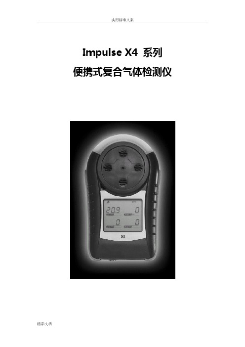
Impulse X4 系列便携式复合气体检测仪操作说明书!重要提示:!在首次使用仪器以前请认真阅读本手册,您将会掌握仪器正确的使用方法和了解仪器的功能,包括操作,维护,功能设置等容。
!为了使操作者更安全,请按照手册中的要求,定期对仪器进行标定。
!如果在使用过程中,遇到的故障或问题在本手册中没有提到,请直接联系制造商Zellweger Analytics,或联系当地的代理商/服务商。
!警告和注意:·更换任何元器件都有可能损坏仪器的本质安全结构。
·如果需要使用存储卡,请选用Zellweger Analytics 提供的存储卡(订货号2566-0435),使用其它的存储卡有可能损坏仪器的本质安全结构。
·在允许的储存期之后激活检测器,有可能影响仪器的使用性能和保质期。
·应使用许可的5号干电池,如劲量电池,不要使用质量低下的干电池,以免影响仪器的本质安全性能。
·在更换电池时,应同时更换2节型号相同的新电池。
·在电池欠压提示后,应尽快更换新电池,以免旧电池漏液损坏仪器。
·在低温环境下,电池的寿命会缩短。
·更换电池时,应该在安全环境下进行。
·当更换任何一个传感器的情况下,都需要对仪器进行标定。
·在每天使用以前,应完成仪器的自检过程。
·定期的对仪器用标气进行测试,检查声、光、振动报警是否正常。
·标定时应选用厂家或国家认证合格企业提供的标准气体。
·标定时应在良好通风的环境下进行,以避免污染。
·不要在仪器电量不足的情况下标定。
·不要在富氧的环境下使用本仪器。
·可燃气体传感器的灵敏度会受到高浓度硫化物,卤素化合物,含硅化合物,以及含铅气体或蒸汽的影响,也叫“中毒”,应避免在以上的环境中使用仪器,如果必须使用,则使用完后应对仪器进行检测和标定,以免影响以后的使用。
霍尼韦尔 S10010 S20010 A使用说明书

® U.S. Registered TrademarkEN0B-0463GE51 R0418Copyright © 2018 Honeywell Inc. • All rights reservedS10010 / S20010SPRING RETURN DIRECT-COUPLED DAMPER ACTUATORS10/20 Nm (88/177 lb-in) FOR MODULATING AND FLOATING CONTROLPRODUCT DATAGENERALThese direct-coupled damper actuators provide modulating / floating control for: ∙ air dampers, ∙ VAV units, ∙ air handlers, ∙ ventilation flaps, ∙ louvers, and∙ reliable control for air damper applications with up to1.5 m 2 / 16 sq.ft (10 Nm / 88 lb-in) or 4.6 m 2 / 50 sq.ft. (20 Nm / 177 lb-in) (seal-less dampers; air friction-dependent).FEATURES∙ Self-centering shaft adapter ∙ Removable access cover∙ Mechanical end limits (non-adjustable)∙Rotation direction selectable by choice of mounting orientation∙ Mountable in any orientation (IP54 only whenmounted on a horizontal shaft with access cover below the shaft)∙ Mechanical position indicatorSPECIFICATIONSSupply voltage S10010 / S20010 24 VAC ±20% / 24 VDC, 50/60 Hz Nominal voltage S10010 / S20010 24 VAC / 24 VDC, 50/60 Hz All values stated hereinafter apply to operation under nominal voltage conditions. Power consumption Holding Driving S10010 5 VA / 5 W 14 VA S20010 5 VA / 5 W 16 VA Ambient limitsAmbient operating limits -40...+60 ︒C Ambient storage limits -40...+70 ︒C Relative humidity 5...95%, non-condensing SafetyProtection standard IP54 Overvoltage category III Lifetime Full strokes 60000 Repositions 1.5 million Full stroke spring return 60000 MountingRound damper shaft 10...27 mm Square damper shaft 13...19 mm Shaft length 25 mm End switch (when included) Rating 5 A (resistive) / 3 A (induct.) Triggering points 7︒ / 85︒ Torque rating S10010 10 Nm (88 lb-in) S20010 20 Nm (177 lb-in) Runtime 90 sec (50 Hz) Spring return timing 20 sec (50 Hz) Rotation stroke 95︒ ± 3︒ Dimensions see Fig. 8 on page 6 Weight 3.2 kg Noise rating Driving 40 dB(A) Holding 20 dB(A) (no audible noise) Spring return 50 dB(A)SmartAct S10010, S20010 – PRODUCT DATAEN0B-0463GE51 R0418 2MODELSorder numbersupply voltage end switchespower consumption torque S1001024 VAC / 24 VDC-- 14 VA (driving) / 5 VA (holding) 10 Nm (88 lb-in) S10010-SW2 2 S20010-- 16 VA (driving) / 5 VA (holding)20 Nm (177 lb-in)S20010-SW2 2Product Identification SystemFig. 1. Product Identification SystemOPERATION / FUNCTIONSContents of Package1 Self-centering shaft adapter2 Retainer clip3 Rotational angle scales (0...90° / 90...0°)4 Mechanical end limits (non-adjustable)5 Hex wrench for manual adjustment6 Rotation direction switch7 Access coverRotary MovementThe actuators are designed to open a damper by driving the damper shaft in either a clockwise or counterclockwise direction.NOTE: Actuators are shipped in the fully-closed (springreturn) position.Position IndicationAn arrow molded into the hub points to tick marks on the label to indicate the hub rotary position.CCW to close (failsafe position)CW to open90°0°45°CW to close (failsafe position)CCW to open90°0°45°Fig. 2. Mounting orientationSmartAct S10010, S20010 – PRODUCT DATA3 EN0B-0463GE51 R0418Manual Adjustment IMPORTANTTo prevent equipment damage, before manual adjustment, you must remove power.The actuator can be operated with no power present. Use this feature during installation or to move and lock the damper or valve shaft position when there is no power.Operating the Manual PositioningTo operate the manual positioning with no power, proceed as follows:1. If the power is ON, turn it OFF.2. Insert the supplied hex wrench (key) as shown in Fig.3. 3. Rotate the key in the direction indicated on the cover.4. Once the desired position has been reached, hold the keyto prevent the spring return from moving the actuator. 5. With the key held in place, use a screwdriver to turn thegear train lock pin in the indicated direction until the detent is reached.NOTE: At the detent, the pin resists further rotation.6. Remove the key without rotating it further.Releasing the Manual PositioningTo release the manual positioning with no power present, proceed as follows:1. Insert the supplied key.2. Turn the key ¼ of a turn in the direction indicated on thecover.3. Remove the key without engaging the gear train lock pin.4. The spring will return the actuator to the failsafe position.NOTE: Once power is restored, the actuator will return tonormal automated control.Fig. 3. Manual positioningInternal End SwitchesNOTE: Only those actuators for which "-SW2" has beenspecified when ordering (e.g.: "S10010-SW2") feature internal end switches.The internal end switches are set to switch from "common" to "normally open" at angles of 7° (±3°) and 85° (±3°), respectively, from the totally counterclockwise position.Fig. 4. Internal end switch triggering pointsMechanical Stroke Limit ReductionFor applications requiring a span of less than 95°, a simple adjustment can be made. When the rotational mounting of the shaft coupling is changed, the actuator drives less than the full 95° stroke.The stroke is adjustable in 5° increments. Once adjusted, the actuator drives until the shaft coupling reaches themechanical stop (part of the housing). The stop causes the motor to discontinue driving, and the shaft coupling drives no farther. When the actuator returns, it stops at the fail-safe position.To set the fail-safe position, proceed as follows:1. Remove the retainer clip from the shaft coupling and set itaside for later use.2. Remove the shaft coupling from the actuator.3. Rotate the coupling to the desired fail-safe position,aligning it based on the stroke labeling. See Fig. 5.EXAMPLE: Setting the shaft coupling to an approx. fail-safeposition of 35° (as indicated on the housing) limits the stroke to 60° (see Fig. 5).4. Install the shaft coupling at this position.5. Replace the retainer clip on the shaft coupling using thegroove of the coupling.6. If necessary, replace the holder and position indicator onthe shaft coupling.SmartAct S10010, S20010 – PRODUCT DATAEN0B-0463GE51 R0418 4Fig. 5. Stroke reductionINSTALLATIONThese actuators are designed for single-point mounting.IMPORTANTTo prevent equipment damage, before manual operation, you must remove power.Mounting InstructionsAll information and steps are included in the Installation Instructions supplied with the actuator.Mounting PositionThe actuators can be mounted in any position (IP54 only when mounted on a horizontal shaft with access cover below the shaft). Choose a mounting position permitting easyaccess to the actuator's cables and controls. When stationing outdoors, equip with suitable cover to protect against UV and rain.Mounting Bracket and ScrewsIf the actuator is to be mounted directly on a damper shaft, use the mounting bracket included in the delivery package.Self-Centering Shaft AdapterThe self-centering shaft adapter can be used for shafts having various diameters and shapes (round: 10...27 mm; square: 13...19 mm).In the case of short shafts, the shaft adapter may be reversed and mounted on the duct side.StrokeThe stroke amounts to 95° ( 3°) and is mechanically limited by end limits (non-adjustable).WiringConnecting to the Power SupplyIn order to comply with protection class II, the power source of 24 V actuators must be reliably separated from the network power supply circuits as per DIN VDE 0106, part 101.Access CoverTo facilitate wiring the actuator to the controller, the access cover can be detached from the actuator.IMPORTANTRemove power before detaching the access cover. Once the access cover has been removed, please take care to avoid damaging any of the parts now accessible.Fig. 6. Access cover (S10010-SW2)Fig. 7. S10010-SW2 with access cover removedSmartAct S10010, S20010 – PRODUCT DATA5 EN0B-0463GE51 R0418Wiring DiagramsS10010 / S20010S10010-SW2 / S20010-SW2NOTE: Internal end switches S1 and S4 must be connected to the same power source.SmartAct S10010, S20010 – PRODUCT DATAManufactured for and on behalf of the Environmental & Energy Solutions Division of Honeywell Technologies Sàrl, Rolle, Z.A. La Pièce 16, Switzerland by its Authorized Representative:Home and Building Technologies Honeywell GmbH Böblinger Strasse 1771101 Schönaich, Germany Phone +49 (0) 7031 637 01 Fax +49 (0) 7031 637 740 EN0B-0463GE51 R0418Subject to change without noticeDIMENSIONS40M I N . 64247MIN. 76MIN. 76757ANTI-ROTATION BRACKET230 mm2 mm20 mm13 mm7 mm10 mmSHAFT ADAPTERALTERNATE POSITION1005050MIN. 15MIN. 155SHAFT ADAPTER SUITABLE FOR SHAFTS WITH LENGTH OF 25 ... 80 mmWHEN THE SHAFT ADAPTER IS INSTALLED IN ALTERNATE POSITION, THE POSITION INDICATOR IS NOT VISIBLE.170 (190)20...25 NmFig. 8. Dimensions (in mm)。
霍尼韦尔控制器S4966V2169电器说明书

故障代码 一
故障代码 二
维护编码
电Байду номын сангаас图纸
霍尼韦尔版面操作--版面
霍尼韦尔版面操作-供暖设置
霍尼韦尔版面操作--供暖设置
霍尼韦尔版面操作--假日设置
霍尼韦尔版面操作--语言设置
霍尼韦尔版面操作--语言设置
霍尼韦尔版面操作--日期设置
霍尼韦尔版面操作--工程人员设置
霍尼韦尔版面操作--工程人员设置
霍尼韦尔版面操作--工程人员设置
霍尼韦尔版面操作--系统设置
霍尼韦尔版面操作--系统设置
霍尼韦尔版面操作--诊断
霍尼韦尔版面操作-诊断设置
霍尼韦尔版面操作--恢复出厂设置
Honeywell TP系列手动开关 说明书

高出面板 齐平面板电气额定值(A)28 VDC115 VDC 250 VDC 115 V AC 60和400 Hz 230 V AC 电气额定值 代码电感 电阻 电灯电阻电阻电感电阻电灯电阻1 15 20 5 0.75 0.5 10 15 3 52 10 15 4 0.75 0.5 7 15 2 63 15 20 7 0.75 0.5 15 154 6 4 10 185 0.75 0.5 8 11 26 5 12 20 5 0.75 0.5 15 15 4 6 6 10 18 4 0.75 0.5 8 11 26特 点 • 两位和三位按钮动作 • 各种按钮颜色• 单极双极和四极电路布置 • 高出面板和齐平面板的安装 •温度范围自-65°F 至+160°F (-54°C 至+71°C) • UL CSA 认证结 构高出面板的安装具有特别的按钮外形齐平面板的安装具有低的按钮外形端子电路标识端子电路标识说明在订货指南中以指示在每个拨动位置上接通哪一些电路 (即:1-2是指通过端子1和2来闭合电路)UL/CSA 额定值代码 电气额定值L192 10A-125,250,277 V AC;1/4马力-125 V AC;1/2马力-250,277 V AC 3A-125V AC “L”L19115 A-125,250,277 V AC;1/4马力-125 V AC;1/2马力-250,277 V AC 5 A-125 V AC “L”应用注意事项:Honeywell MICRO SWITCH 不建议在无弧负载下采用银镉氧化物触头无弧负载一般加载到低于12V 和/或0.5A TP 开关采用银镉氧化物触头如您有什么特殊问题请打电话1-800-537-6945与Honeywell MICRO SWITCH 应用中心联系 键槽侧 共用(2,5,8,11)四极共用(2,5)键槽侧双极共用(2)键槽侧可拆塑料 按钮 标记片 单件管套和盖 封闭开关室模制铸入端子插入件弹性体密封件安装孔 盖密封件 锁紧装置高强度耐温无漏电塑料开关壳典型的双极与齐平面板 的半透明按钮开关典型的单极高出面板 的透明按钮开关按钮选项按钮是可拆卸的并可互换按钮尺寸为.87”×1.46”(22,1×37,1mm)透明(无色塑料)按钮允许使用 “表面下”用于识别工作站和功能的图标符号插件图标符号插件不予提供插件上标注图标符号可由您所在地的供应商制作半透明(白色塑料)按钮的外观清晰明亮彩色(不透明塑料)按钮特别适用于彩色代码开关装置图标符号的标注MICRO SWITCH 在按钮表面上提供热压印的图标符号标注使用TP 图标符号订货单FO-53730来规定您所要求的图标符号更多的复制件可从离您最近的MICRO SWITCH 销售办公处获取MICRO SWITCH 不提供标注图标符号插件的服务)半透明和不透明按钮也可由用户刻制和填写不带按钮的开关为订购不带按钮的开关要改变订货指南中所示的目录号用TP7来代替TP4和TP16型高出面板安装的开关;用TP8来代替TP201和TP12型齐平面板安装的开关至于按钮则按下表单独订购按钮订货指南*不透明TP2-位(开关)订货指南 同时供应按钮按钮在以下位置时电路接通:目录号齐平面板高出面板 极数标识片位置标识片对面UL/CSA 额定值代码电气额定值代码 半透明按钮 透明按钮 半透明按钮 透明 按钮 1 OFF *OFF* 1-2* 1-2* 1-2*2-3 2-3 OFF 2-3 2-3 L191 L192 L192 L191 L192 1 2 2 1 2 1TP201-2 1TP201-4 1TP201-6 1TP201-3 1TP201-8 1TP12-2 1TP12-4 1TP12-6 1TP12-3 1TP12-8 1TP216-2 1TP216-4 1TP216-6 1TP216-3 1TP216-8 1TP4-2 1TP4-4 1TP4-6 1TP4-3 1TP4-8 2 OFF *OFF* 1-2,4-5* 1-2,4-5* 1-2,4-5*2-3,5-6 2-3,5-6 OFF 2-3,5-6 2-3,5-6 L191 L192 L192 L191 L192 3 4 4 3 4 2TP201-2 2TP201-4 2TP201-6 2TP201-3 2TP201-8 2TP12-2 2TP12-4 2TP12-6 2TP12-3 2TP12-8 2TP216-2 2TP216-4 2TP216-6 2TP216-3 2TP216-82TP4-2 2TP4-4 2TP4-6 2TP4-3 2TP4-8 4 OFF *OFF* 1-2,4-5,7-8,10-11* 1-2,4-5,7-8,10-11* 1-2,4-5,7-8,10-11*2-3,5-6,8-9,11-12 2-3,5-6,8-9,11-12OFF 2-3,5-6,8-9,11-12 2-3,5-6,8-9,11-12L191 L192 L192 L191 L192 5 6 6 5 64TP201-1 4TP201-4 4TP201-6 4TP201-3 4TP201-84TP12-2 4TP12-4 4TP12-6 4TP12-3 4TP12-8- 4TP216-4- 4TP216-3 4TP216-84TP4-2 4TP4-4 - 4TP4-3 -颜 色 目录号 半透明 透明 白色* 黄色* 黑色* 绿色* 红色* 蓝色* 12PA6 12PA4 12PA5-W 12PA5-Y 12PA5-BK 12PA5-G 12PA5-R 12PA5-BLTP 3-位(开关)订货指南 同时供应按钮按钮在以下位置时接通电路极 数标识片 位置 中心位置 对面 标识片UL/CSA 额定值代码 电气额定值代码1 1-2 1-2* 1-2* 无* * 无**无**1-2*OFFOFFOFFOFF1-2 1-2 OFF 2-3 2-3 2-3* 2-3* 2-3 2-3* 无** L191 L192 L192 L191 L191 L192 L192 1 2 2 1 1 2 2 1TP201-11TP201-51TP201-71TP201-211TP201-311TP201-511TP201-611TP12-1 1TP12-5 1TP12-7 1TP12-21 1TP12-31 1TP12-51 1TP12-61 1TP216-11TP216-51TP216-7--1TP216-511TP216-611TP4-1 1TP4-5 1TP4-7 1TP4-21 1TP4-31 1TP4-51 1TP4-61 2 1-2,4-5 1-2,4-5* 1-2,4-5* 无**无**无**1-2,4-5*1-2,4-51-2,4-5*1-2,4-5*OFFOFFOFFOFF 1-2,4-5 1-2,4-5 OFF 1-2,5-6 1-2,5-6 1-2,5-6 2-3,5-6 2-3,5-6 2-3,5-6* 2-3,5-6 2-3,5-6 2-3,5-6* 无** 2-3,5-6 2-3,5-6 2-3,5-6* L191 L192 L192 L191 L191 L192 L192 L191 L192 L192 3 4 4 3 3 4 4 3 4 4 2TP201-12TP201-52TP201-72TP201-212TP201-312TP201-5122TP201-612TP201-10g 2TP201-50g 2TP201-70g 2TP12-1 2TP12-5 2TP12-7 2TP12-21 2TP12-31 2TP12-512 2TP12-61 2TP12-10g 2TP12-50g 2TP12-70g2TP216-12TP216-52TP216-72TP216-212TP216-312TP216-512 2TP216-612TP216-10g 2TP216-50g 2TP216-70g 2TP4-1 2TP4-5 2TP4-7 2TP4-21 2TP4-31 2TP4-5122TP4-61 2TP4-10g 2TP4-50g 2TP4-70g4 1-2,4-5, 7-8,10-111-2,4-57-8,10-11*1-2,4-5,7-8,10-11*无**无**无**1-2,4-5,7-8,10-11*1-2,4-5,7-8,10-111-2,4-5,7-8.10-11* 1-2,4-5,7-8,10-11*OFFOFF OFF OFF 1-2,4-5 7-8,10-11 1-2,4-5 7-8,10-11 OFF 2-3,4-5 2-3,4-5 7-8,11-12 2-3,4-5 2-3,5-6 8-9,11-12 2-3,5-6 8-9,11-12 2-3,5-6 8-9,11-12* 2-3,5-6 8-9,11-12 2-3,5-6 8-9,11-12 2-3,5-6 8-9,11-12* 无** 2-3,5-6 8-9,11-12 2-3,5-6 8-9,11-122-3,5-6 8-9,11-12* L191 L192 L192 L191 L191 L192 L192 L191 L192 L192 5 6 6 5 5 6 6 5 6 64TP201-14TP201-54TP201-74TP201-214TP201-314TP201-514TP201-614TP201-10g4TP201-50g4TP201-70g 4TP12-1 4TP12-5 4TP12-7 4TP12-21 - - 4TP12-61 4TP12-10g4TP12-50g4TP12-70g4TP216-1-4TP216-74TP216-214TP216-314TP216-514TP216-61-4TP216-50g4TP216-70g 4TP4-1 4TP4-5 4TP4-7 4TP4-21 4TP4-31 4TP4-51 4TP4-61 4TP4-10g 4TP4-50g4TP4-70g*这些位置仅是自复位的所有其它位置则是保持的**操作器被挡在这些位置上开关变成两位开关中心位置成为一个极端位置✝是特殊的on-on-on 电路系统安装尺寸(仅供参考)高出面板 齐平面板32°总行程4极有6-32 UNC-28螺纹的锁紧螺母面板开孔 单极直径双极四极埋头孔按需要钻出(2)0,0=mm 图例:0,00=in塑料按钮 (可拆卸)6-32 UNC-28螺纹 带锁定装置(2)6-32 UNC-28螺纹 带锁定装置(2)塑料按钮 (可拆卸)尺寸极 极极 极尺寸总行程接线用圆顶宽边接头螺钉和锁紧垫圈(SEMS)。
霍尼韦尔XI582手提操作终端使用说明

X I582手提操作终端X I582操作使用说明Operation Manual霍尼韦尔自动化控制系统集团广州办事处广州市海珠区滨江中路路308号海运大厦15层A座86-020-********郑仲华目录1.概述 (3)2. 菜单引进式说明 (3)3. 按键说明 (3)4. 菜单说明 (4)4.1 系统主菜单说明 (4)4.2 密码校验 (4)4.3 登录后的主菜单 (6)5、时间程序 (6)5.1 时间表定义 (8)5.2 日时间表的编辑 (8)5.3 周时间表编辑 (11)5.4 年时间表编辑 (12)6. 数据点的查看及控制 (12)7. 系统的时间及日期 (16)8. 系统数据配置 (16)8.1 通讯接口配置 (17)8.2 系统程序备份 (19)8.3 远程登录同一条CBUS的其它DDC (23)9. 注意事项 (25)10. 关于本手册 (25)1.概述XI582操作终端是作为附于XL5000系列控制器的操作界面,提供简单、多功能、菜单引进的显示形式,用来观察及修改数据,如设定值,控制状态及开关状态等。
键盘上的健功能放弃使用名称方法而使用符号来表示。
口令保护确保只有授权人士方可以访问数据。
提供报警处理功能以满足系统的完整性,显示屏提供当前报警的信号资料,有助于操作人员很快判别报警情况的优先次序。
2.菜单引进式说明采用LCD液晶显示屏幕,提供4行,每行17个字符显示。
3.按键说明提供有8个刻有明确符号,轻触式按键键盘。
--(取消键)中止操作过程并退回较高层次菜单。
--(左箭头)移动光标到本行的上一个相连区域,当光标退到前端,将跳至上一行的最后一个相连区域。
--(上箭头)移动光标到上一行的相连区域。
--(下箭头)移动光标到下一行的相连区域。
--(右箭头)移动光标到本行的上一个相连区域,当光标退到前端,将跳至上一行的最后一个相连区域。
--(回车确认键)从菜单中选择指令及功能,这个健可以用作界定需修改的区域及确认修改。