HC110111001 命令行基础
南方安华A100变频器说明书

南方安华A100变频器说明书南方安华A100 系列变频调速器使用手册 V1.9 深圳市南方安华电子科技有限公司SHENZHEN NOWFOREVER ELECTRONICS TECHNOLOGY CO.LTD. 目录开箱检查...................................................................... ................... 1软件更新说明...................................................................... ........... 21 安全注意事项 ..................................................................... ........ 4 1.1 安全事项...................................................................... ................... 4 1.2 注意事项...................................................................... ................... 62 概述...................................................................... ....................... 9 2.1 铭牌说明...................................................................... ................... 9 2.2 产品信息...................................................................... ................... 9 2.3 系列型号说明...................................................................... ......... 10 2.3.1 220V 系列说明.. (10)2.3.2 380V 系列说明 (11)2.4 技术规范.................................................................. ..................... 13 2.5 性能特点...................................................................... ................. 14 2.6 直流电抗器选件说明. (15)2.7 制动电阻选型指南.......................................................................16 2.8 制动电阻连接说明.......................................................................17 2.9 注塑机信号板的连接说明........................................................... 173 安装.................................................................. ......................... 19 3.1 安装环境...................................................................... ................. 19 3.2 安装方向与空间...................................................................... ..... 19 3.3 变频器的安装尺寸....................................................................... 204 接线.................................................................. ......................... 24 4.1 外围设备的连接........................................................................... 24 4.2 主回路端子说明...................................................................... ..... 25 4.2.1 接线方式...................................................................... .... 25 4.2.2 变频器主回路端子说明及配线...................................... 27 4.3 控制回路端子说明.................................................................. ..... 28 4.3.1 控制回路端子布局.......................................................... 29 4.3.2 控制回路端子说明..........................................................29 4.3.3 控制回路端子接线说明.................................................. 30 4.3.4 控制回路跳线及其他接口说明...................................... 325 操作.................................................................. ......................... 34 5.1 操作键盘说明...................................................................... ......... 34 5.1.1 操作键盘示意图.. (34)5.1.2 按键功能说明..................................................................34 5.1.3 指示灯说明.................................................................. .... 35 5.1.4 数码管显示......................................................................36 5.2 操作方法.................................................................. ..................... 37 5.2.1 快速监视...................................................................... .... 37 5.2.2 功能码设置.................................................................. .... 37 5.2.3 信息查询...................................................................... .... 38 5.2.4 故障报警复位 (38)5.2.5 键盘数字设定快速修改.................................................. 38 5.3 电机参数自学习.................................................................. ......... 39 5.4 快速调试...................................................................... ................. 396 详细功能码设置说明............................................................... 406.1 P0 功能组.................................................................. .................... 40 6.1.1 基本功能...................................................................... .... 40 6.1.2 电机参数.......................................................................... 45 6.1.3 V/F 曲线参数. (46)6.1.4 VVVF 控制参数 (47)6.1.5 矢量控制参数 (48)6.1.6 输入端子...................................................................... .... 49 6.1.7 输出端子...................................................................... .... 54 6.1.8 起停控制...................................................................... .... 56 6.1.9 加减速辅助......................................................................59 6.1.10 辅助功能...................................................................... .. 60 6.1.11 键盘设置...................................................................... .. 63 6.1.12 保护功能设置. (63)6.1.13 多段速和简易PLC......................................................... 67 6.1.14 PID 控制.................................................................. ....... 72 6.1.15 摆频设置...................................................................... .. 74 6.1.16 串行通讯设置. (75)6.1.17 计数、定时功能............................................................ 76 6.1.18 预留功能组....................................................................77 6.1.19 功能码修改设置............................................................ 79 6.2 P1 功能组(供应商设置).......................................................... 79 6.3 d 功能组(只读)..................................................................... ... 807 故障报警和对策 ..................................................................... .. 81 7.1 故障和报警...................................................................... ............. 81 7.1.1 故障指示及故障复位...................................................... 81 7.1.2 报警指示及报警复位 (81)7.2 故障报警及对策.................................................................. ......... 81 7.3 常见故障的处理方法. (83)7.3.1 上电无显示......................................................................83 7.3.2 变频器运行后电机不运转.............................................. 838 保养和维护 ................................................................. .............. 85 8.1 定期检查...................................................................... ................. 85 8.2 零部件更换年限...................................................................... ..... 85 8.3 保修说明...................................................................... ................. 869 功能码一览表 ................................................................. .......... 87 9.1 P0 功能组(用户设置功能码).................................................. 87 9.2 P1 功能组(供应商设置功能码)............................................ 104 9.3d0 功能组(历史故障信息).................................................... 105 9.4 d1功能组(变频器信息)........................................................ 105 9.5d2 功能组(变频器运行状态)................................................ 106 9.6 d3 功能组(用户接口状态).................................................... 10810 MODBUS 通讯协议.................................................................. 110 10.1 MODBUS 通信的构成 (110)10.2 信息格式.................................................................. ................. 110 10.3 MODBUS 信息示例...................................................................... 112 10.3.1 读取存储寄存器的内容.............................................. 112 10.3.2 回路测试.................................................................. .... 112 10.3.3 向多个存储寄存器的写入.......................................... 113 10.3.4 数据保存指令.. (114)10.3.5 广播式发送数据 (114)10.4 变频器为从站.................................................................. ......... 114 10.4.1 指令数据.................................................................. .... 114 10.4.2 监视数据.................................................................. .... 114 10.4.3 设置数据.................................................................. .... 115 10.4.4 测试数据.................................................................. .... 115 10.5 变频器为主站.................................................................. ......... 115 10.6 MODBUS 通讯错误代码.. (115)10.7 从机无响应故障检查............................................................... 116图表索引.................................................................. ................... 117南方安华变频器说明书详细功能码设置说明开箱检查开箱前请确认产品包装箱无运输中造成的破损现象。
HC110110003 IP编址

Copyright © 2014 Huawei Technologies Co., Ltd. All rights reserved.
Page 20
无类域间路由
10.24.0.0/24
通告路由 10.24.0.0/22
10.24.1.0/24
10.24.2.0/24
10.24.3.0/24
CIDR 增OGIES CO., LTD.
前言
网络层位于数据链路层与传输层之间。网络层中包含了许多协议,其中最
为重要的协议就是IP协议。网络层提供了IP路由功能。理解IP路由除了要
熟悉IP协议的工作机制之外,还必须理解IP编址以及如何合理地使用IP地 址来设计网络。
Copyright © 2014 Huawei Technologies Co., Ltd. All rights reserved.
192 128 126
.168
Copyright © 2014 Huawei Technologies Co., Ltd. All rights reserved.
Page 19
变长子网掩码举例
20个主机
30个主机 10个主机
现有一个C类网络地址段192.168.1.0/24,请使用变长子网掩码给三个子 网分别分配IP地址。
二进制、十进制和十六进制
进制 二进制 十进制 十六进制
字符范围 0—1 0—9 0 —9,A — F
基值 2 10 16
在IP网络中,二进制和十六进制是常用的编码方式。
Page 8
Copyright © 2014 Huawei Technologies Co., Ltd. All rights reserved.
P110C控制模块使用说明书

P110C 控制模块使用说明书一.一般介绍图1图2图3图41.由图1、图2可见P110C几乎每一个端口都是多功能的,用户可通过编程选用其中任何一项功能。
2. P110C可在2.4V-5.5V供电电压下工作,它自身的耗电可由用户通过编程设定(有4挡功耗模式选择)在0.5微安(μA)—3.5毫安(mA)之间,因此,即便是用电池供电也可长期稳定工作。
3. P110C 可在 -40℃— +75℃环境温度下长期稳定工作。
4.由图3可见P110C的外型尺寸为标准24脚DIP封装集成电路形式,因此,它可同标准插座配合。
5. 图4描述了P110C-B 的外观尺寸。
P110C-B就是带印刷电路板的P110C(它上面插了一个P110C模块),印刷电路板上接线端的排列与P110C管脚一一对应。
不想自己制做印刷电路板的用户可选用P110C-B。
二.P110C可编程控制模块外部端口介绍1.有二十个通用输出/输入(I/O)端口(P000---P019),每个端口即可做输入也可做输出。
在做输出时每个端口可输出至少10毫安(mA)电流(不论是高电平输出还是低电平输出),因此每个端口都可单独驱动LED发光二极管或光电耦合器。
2.有一路模拟比较输入端口(AN+/AN-)。
3.有七个模/数转换(ADC)输入端口(ADC0---ADC6),每个都具有10位的分辩精度,转换时间52微秒(μS),模拟参考电压为VCC 。
4.有六个脉冲宽度调制(PWM)输出端口(PWM0---PWM5),每路的输出脉冲宽度均可在0%--100%之间调整,脉冲输出极性可正向也可反向,脉冲输出频率可在15HZ—15KHZ之间调整,利用上述特性,可同时控制三台直流电动机的调速运行,或实现三路数/模转换(DAC)输出。
5.有三个频率输出端口(FRE0-FRE2),每路的输出频率均可在1HZ—15.686KHZ 间调整,可同时控制三台步进电机的调速运行,或实现三路频率输出。
西门子 S7-300和S7-400语句表(STL)编程 说明书
前言,目录 位逻辑指令 1 比较指令 2 转换指令 3 计数器指令 4 数据块指令 5 逻辑控制指令 6 整数运算指令 7 浮点数运算指令 8 装载和传送指令 9 程序控制指令 10 移位和循环移位指令 11 定时器指令 12 字逻辑指令 13 累加器指令 14附录所有语句表指令一览 A 编程举例 B 参数传递 CSIMATICS7-300和S7-400 语句表(STL )编程参考手册2006年3月版A5E00706960-01索引安全指南本手册包括应该遵守的注意事项,以保证人身安全及财产损失。
在本手册中,与人身安全有关的注意事项通过安全警告符号突出显示,而只与财产损失有关的注意事项则没有安全警告符号。
这些注意事项根据危险等级显示如下:危险表示若不采取适当的预防措施,将导致死亡或严重的人身伤害。
警告表示若不采取适当的预防措施,将可能导致死亡或严重的人身伤害。
小心带安全警告符号时,表示若不采取适当的预防措施,将导致轻微的人身伤害。
小心不带安全警告符号时,表示若不采取适当的预防措施,将造成财产损失。
注意如果不引起相应的重视,将会导致意外的结果或状态。
当出现多个安全等级时,应该采用最高危险等级的安全提示。
带安全警告符号的人员伤害警告也可能会导致财产损失。
合格人员只有合格人员才允许对设备/系统进行调试和操作。
合格人员规定为根据既定的安全惯例和标准,被授权对设备、系统和电路进行调试、接地和加装标签的人员。
正确使用请注意如下事项:警告该装置及其组件只能用于产品目录或技术说明书中所阐述的应用,并且只能与由西门子公司认可或推荐的第三方厂商提供的设备或组件一起使用。
本产品只有在正确的运输、贮存、设置和安装以及仔细地运行和维护的情况下,才能正确而安全地运行。
商标标有®的所有名称均为西门子公司的注册商标。
本文档中的其它一些标志也是注册商标,如果任何第三方出于个人目的而使用,都会侵犯商标所有者的权利。
郑重声明我们已核对过本手册的内容与所述硬件和软件相符。
HC防火墙命令行配置

H C防火墙命令行配置 Last updated on the afternoon of January 3, 2021配置防火墙网页登录1.配置防火墙缺省允许报文通过<telecom>system-view[telecom]firewallpacket-filterenable[telecom]firewallpacket-filterdefaultpermit为防火墙的以太网接口(GigabitEthernet0/0为例)配置IP地址,并将接口加入到安全域。
[telecom]interfaceGigabitEthernet0/0[telecom-GigabitEthernet0/0]ipaddress[telecom-GigabitEthernet0/0]quit[telecom]firewallzonetrust[telecom-zone-trust]addGigabitEthernet0/02.添加登录用户(建立一个账户名和密码都为admin的账户类型为telnet)[telecom]local-useradmin[telecom-luser-admin]passwordsimpleadmin[telecom-luser-admin]service-typetelnet3.在GigabitEthernet0/1接口上配置FTP及www内部服务器[telecom]interfaceGigabitEthernet0/1[telecom-GigabitEthernet0/1]ipaddress[telecom-GigabitEthernet0/1]natoutbound2000[telecom-GigabitEthernet0/1]natserverprotocoltcpglobalwwwinside[telecom-GigabitEthernet0/1]natserverprotocoltcpglobalftpinside [telecom-GigabitEthernet0/1]quit[telecom]aclnumber2000[telecom-acl-basic-2000]rule0permitsource[telecom-acl-basic-2000]rule1deny4.IPSecVPN配置VPN总公司端VPN配置步骤如下:[telecom]aclnumber3000[telecom-acl-adv-3000]rule0denyipsourcedestination [telecom-acl-adv-3000]rulepermitip[telecom-acl-adv-3000]quit[telecom]aclnumber3200[telecom-acl-adv-3200]rule0permitipsourcedestination [telecom-acl-adv-3200]quit第三步:配置本端设备名称为routera[telecom]ikelocal-nameroutera第四步:配置对等体peer[telecom]ikepeerpeer[telecom-ike-peer-peer]exchange-modeaggressive[telecom-ike-peer-peer]pre-shared-key123456[telecom-ike-peer-peer]id-typename[telecom-ike-peer-peer]remote-nametelecom[telecom-ike-peer-peer]nattraversal第五步:配置IPSec安全提议test[telecom]ipsecproposaltest[telecom-ipsec-proposal-test]encapsulation-modetunnel [telecom-ipsec-proposal-test]transformesp[telecom-ipsec-proposal-test]espencryption-algorithm3des [telecom-ipsec-proposal-test]espauthentication-algorithmmd5 [telecom-ipsec-proposal-test]quit第六步:创建安全策略test并指定通过IKE协商建立SA [telecom]ipsecpolicytest1isakmp第七步:配置安全策略test引用IKE对等体peer[telecom-ipsec-policy-isakmp-test-1]ike-peerpeer第八步:配置安全策略test引用访问控制列表3200 [telecom-ipsec-policy-isakmp-test-1]securityacl3200第九步:配置安全策略test引用IPSec安全提议test [telecom-ipsec-policy-isakmp-test-1]proposaltest[telecom-ipsec-policy-isakmp-test-1]quit第十步:配置上行接口IP地址/24,并在接口上应用IPSec策略[telecom]intGigabitEthernet0/0[telecom-GigabitEthernet0/0]ipaddress24[telecom-GigabitEthernet0/0]natoutbound3000[telecom-GigabitEthernet0/0]ipsecpolicytest第十一步:配置下行接口IP地址/24[telecom-GigabitEthernet0/1]ipaddress24第十二步:配置到分公司局域网的静态路由[telecom]iproute-static开启telnet服务并设置密码为123456命令:[telecom]telnetserverenable[telecom]user-interfacevty0[telecom-ui-vty0]authentication-modepassword[telecom-ui-vty0]setauthenticationpasswordsimple123465(cipher明文/simple 密文)[telecom-ui-vty0]userprivilegelevel3[telecom-ui-vty0]quit操作命令:displayversion显示系统版本信息vrbd显示详细的软件版本信息displayclock显示系统时钟clockdatetime14:56:0023/2/2017修改系统时钟为2017年2月23日14时56分0秒displayusers[all]显示终端用户reboot重启防火墙save保存当前配置resetsave清空当前配置displayinterfaceGigabitEtherneto/1查看某个端口信息displayinterface查看所有端口信息displaybriefinterfaceGigabitEtherneto/1查看端口简要配置displayport-security查看端口安全配置信息info-centerenable开启信息中心undoinfo-centerenable关闭信息中心displayarp显示arpdisplayloopback-detection用来测试环路测试是否开启displaysaved-configuration显示下次启动时加载的配置文件displaystartup显示系统本次启动使用的配置文件displaysaved-configuration显示起始配置信息displaycurrent-configuration显示当前配置信息displaymemory[limit]显示当前系统内存使用情况displaycpu-usage显示CPU占用率情况displaycpu-usagehistory统计系统cpu占用率历史信息displaydevice[slot-id]显示设备和插卡的信息displayiprouting-table显示当前路由表iproute-static目的地址掩码下一跳的地址[端口][管理距离] telnetserverenable开启telnet服务displayhistory-command查看保存的历史命令displayhotkey查看热键信息hotkey将某快捷键与某一命令行关联(格式为hotkey快捷键一段命令)superpasswordlevel3simple123456设置用户密码和级别(0-3级别)sysname设置防火墙的名称(格式为sysnamexxx)command-aliasenable开启用户别名功能command-aliasmapping[将要被定义的命令][命名的别名]例如:command-aliasmappingdisplayshowdisplaycommand-alias显示当前用户设置别名的情况schedulerebootat[hh:mm][月/日/年]定时重新启动(在用户模式下)schedulerebootdelay{小时|分钟}延时启动tracert跟踪地址。
华为CX110交换机模块V100R001C10白皮书说明书
Huawei CX110 Switch Module V100R001C10White PaperIssue06Date2017-03-27Copyright © Huawei Technologies Co., Ltd. 2017. All rights reserved.No part of this document may be reproduced or transmitted in any form or by any means without prior written consent of Huawei Technologies Co., Ltd.Trademarks and Permissionsand other Huawei trademarks are trademarks of Huawei Technologies Co., Ltd.All other trademarks and trade names mentioned in this document are the property of their respective holders.NoticeThe purchased products, services and features are stipulated by the contract made between Huawei and the customer. All or part of the products, services and features described in this document may not be within the purchase scope or the usage scope. Unless otherwise specified in the contract, all statements, information, and recommendations in this document are provided "AS IS" without warranties, guarantees or representations of any kind, either express or implied.The information in this document is subject to change without notice. Every effort has been made in the preparation of this document to ensure accuracy of the contents, but all statements, information, and recommendations in this document do not constitute a warranty of any kind, express or implied.Huawei Technologies Co., Ltd.Address:Huawei Industrial BaseBantian, LonggangShenzhen 518129People's Republic of ChinaWebsite:About This DocumentPurposeThis document describes the E9000 CX110 GE switch module (CX110 for short) in terms ofits functions, advantages, appearance, specifications, internal networking, standards andcertifications. You can learn about the CX110 by reading this document.The product features and commands for the ethernet switching plane of the switch modulesvary according to the software version. For details, see the documents listed in the followingtable.Intended AudienceThis document is intended for:l Huawei presales engineersl Channel partner presales engineersl Enterprise presales engineersSymbol ConventionsThe symbols that may be found in this document are defined as follows:Change HistoryIssue 06 (2017-03-17)This issue is the third official release.Issue 05 (2017-02-17)This issue is the fifth official release.Issue 04 (2016-11-22)This issue is the fourth official release.Issue 03 (2016-05-12)This issue is the third official release.Issue 02 (2015-07-17)This issue is the second official release.Issue 01 (2015-02-16)This issue is the first official release.White Paper ContentsContentsAbout This Document (ii)1 Introduction (1)1.1 Function (2)1.2 Advantages (8)1.3 Appearance (9)1.4 Ports (13)1.5 Indicator (17)1.6 Internal Chassis Networking (19)1.7 Software and Hardware Compatibility (21)1.8 Technical specifications (23)2 Standards and Certifications (26)2.1 Standards Compliance (27)2.2 Certifications (29)1 Introduction About This Chapter1.1 FunctionThis topic describes the functions, protocols, and ports of the CX110 GE switch module.1.2 AdvantagesThe CX110 provides various ports (GE/10GE/40GE) and high specifications, and supportslarge data center networks, high-performance stacking, and various data center features. Inaddition, the CX110 switch module can be easily deployed and maintained.1.3 AppearanceThis topic describes the CX110 in terms of its appearance, panel, and installation positions inthe chassis.1.4 PortsThis topic describes the features, number rules, names, types, quantities, subcard numbers,and port numbers of the CX110 ports.1.5 IndicatorThis topic describes the indicators on the CX110.1.6 Internal Chassis NetworkingThis topic describes connection relationships between the CX110 and mezz modules oncompute nodes.1.7 Software and Hardware CompatibilityThis topic describes mezz modules that can work with the CX110 and pluggable modules andcables supported by ports on the CX110 panel.1.8 Technical specificationsThis topic describes the physical, environmental, power, and network switching specificationsof the CX110.1.1 FunctionThis topic describes the functions, protocols, and ports of the CX110 GE switch module.The CX110 GE switch module (CX110 for short) is a switch control unit that provides dataswitching function for service slots in the system and centrally provides service andmanagement ports for external devices.The CX110 is installed in the rear slot of the E9000 chassis and connected to compute nodes,storage nodes, management modules through the E9000 midplane. The CX110 performsswitching of internal data packets and control management packets to provide high-speed datatransmission.Table 1-1 describes the functions of the CX110.Table 1-1 GE switching plane function description1.2 AdvantagesThe CX110 provides various ports (GE/10GE/40GE) and high specifications, and supportslarge data center networks, high-performance stacking, and various data center features. Inaddition, the CX110 switch module can be easily deployed and maintained.Various Ports (GE/10GE/40GE)Underpinned by the leading hardware platform, the CX110 provides high-density ports andand a line-speed forwarding capability.The CX110 provides four 10GE ports and 12 GE electrical ports for connecting upstream toconvergence/core switches, 34 GE ports for interconnecting with high-performance computenodes, and two 40GE ports for interconnecting with and stacking switch boards.High Specifications and Support for Large Data Center NetworksThe CX110 provides the highest specifications in the industry. It supports a maximum of131,072 MAC addresses, a maximum of 16,384 forwarding information bases (FIBs), and amaximum of 4,096 multicast prefix tables.High-Performance Stacking, Easy Deployment and MaintenanceThe CX110 supports stacking of four devices. It has the following advantages:l High performance: A single stacking system can provide eight 10GE and 24 GE uplink ports (two devices are stacked).l High bandwidth: The CX110 supports 80GE stacking bandwidth. The stacking system has no bandwidth bottlenecks.l Easy deployment and maintenance:–Pre-deployment and offline configuration are supported. The system can be pre-planned and pre-configured. Devices can be added as required, supporting plug andplay and Pay As You Grow.–The slot ID of a device is the ID in a stacking system, facilitating deviceidentification and maintenance.–Indicators on the front panel indicate the role and status of a stacking system. Thestacking system can be maintained without a terminal.l Simple upgrade operations: The stacking system supports quick and automatic software upgrades, simplifying upgrade operations and reducing upgrade workload.Various Data Center Featuresl Virtual/virtual machine (VM) access–Supports virtualized servers, improving data center utilization.–Supports virtual resource discovery. During migration of VMs, VM networkpolicies can be automatically migrated using the virtual resource discovery functionso that network resources can be allocated as required. Working with the large-scalelayer 2 network, VMs can be freely migrated inside the whole data center.l Transparent Interconnection of Lots of Links (TRILL) protocol–Complying with the Internet Engineering Task Force (IETF) standard, the TRILLprotocol supports ultra-large networks and flexible networking modes.–The TRILL protocol supports load balancing by paths, so that traffic can be sharedbetween multiple paths according to service requirements.–The TRILL protocol supports sub-second network convergence. Any changes onthe network can be quickly sensed and then fast convergence is performed.1.3 AppearanceThis topic describes the CX110 in terms of its appearance, panel, and installation positions inthe chassis.AppearanceFigure 1-1 shows the CX110.Figure 1-1 AppearanceInstallation PositionsThe CX110 can be installed in the four slots at the rear of the E9000 chassis. The four slots are 1E, 2X, 3X, and 4E, as shown in Figure 1-2.Figure 1-2 Installation positions and slot numberingPanelFigure 1-3 shows the CX110 panel.Figure 1-3 Panel1Product model 2Customization label (with an ESN label)3Stacking status indicator 4Health status indicator 5Offline button/indicator 6BMC serial port 7GE electrical port810GE optical port9Data transmission status indicator of the 10GE optical port 10Connection status indicator of the 10GE optical port 11GE electrical port indicator12SYS serial portThe numbers on the left side are port serial numbers. The arrow direction of a triangle indicates the direction of a port.ESNsAn Equipment Serial Number (ESN) is a string that uniquely identifies a server. An ESN is required when you apply for technical support from Huawei.Figure 1-4 shows the ESN format.Figure 1-4 ESN example1.4 PortsThis topic describes the features, number rules, names, types, quantities, subcard numbers,and port numbers of the CX110 ports.The CX110 Ethernet ports are numbered in Slot number/Subcard number/Port numberformat.l Slot number: indicates the slot number of the current switch module. The value ranges from 1 to 4, mapping to 1E, 2X, 3X, and 4E slot respectively from left to right on thepanel.l Subcard number: indicates the number of a subcard supported by service ports. Thevalue ranges from 1 to 20. Table 1-2 and Table 1-3 describe subcard numbers.l Port number: indicates the sequence number of a port on a subcard. Table 1-2 and Table 1-3 describe port numbers and subcards.For example, if the CX110 is in slot 2X, the first GE port on the upper right on the panel isnumbered as GE 2/17/12, as shown in Figure 1-5.Figure 1-5 Port naming rulesTable 1-2 describes the external ports on the CX110.Table 1-2 External portsTable 1-3 describes the internal ports on the CX110. Table 1-3 Internal ports1.5 IndicatorThis topic describes the indicators on the CX110.You can observe the indicators to determine the current operating status of the CX110. Table1-4 describes the indicators.Table 1-4 Indicator description1.6 Internal Chassis NetworkingThis topic describes connection relationships between the CX110 and mezz modules oncompute nodes.For details about the networking of the CX110 and Mezz cards on compute nodes, see E9000Blade Server Mezz Module-Switch Module Interface Mapping Tool.Figure 1-6 shows the internal chassis networking for the CX110 and compute nodes. Ports oncompute nodes for connecting to the CX110 are provided by two mezz modules as follows:l Mezz 1 connects to GE switching planes of the CX110s in slots 2X and 3X.l Mezz 2 connects to GE switching planes of the CX110s in slots 1E and 4E.Figure 1-6 Mapping between the CX110 and mezz modules on compute nodesThe following describes the mapping between the CX110s and mezz modules. For example,the CX110s are installed in slots 2X and 3X and connect to Mezz 1.Port Mapping Between a Switch Module and a Mezz ModuleMapping between the CX110 and ports on the MZ110The MZ110 provides four GE ports, including ports 1, 2, 3, and 4. Ports 1 and 2 map to theGE switching plane of the CX110 in slot 2X, and ports 3 and 4 map to the GE switching planeof the CX110 in slot 3X, as shown in Figure 1-7.Figure 1-7 Mapping between the CX110 and ports on the MZ110Mapping between the CX110 and ports on the MZ111The MZ111 provides four GE ports, including ports 1, 2, 3, and 4. Ports 1 and 3 map to theGE switching plane of the CX110 in slot 2X, and ports 2 and 4 map to the GE switching planeof the CX110 in slot 3X, as shown in Figure 1-8.Figure 1-8 Mapping between the CX110 and ports on the MZ1111.7 Software and Hardware CompatibilityThis topic describes mezz modules that can work with the CX110 and pluggable modules andcables supported by ports on the CX110 panel.For details about the software and hardware that are compatible with the CX110, see HuaweiServer Compatibility Checker.Supported Mezz ModulesThe CX110 connects to mezz modules of compute nodes. Table 1-5 describes models andspecifications of the supported mezz modules.Table 1-5 Supported mezz modulesSupported Pluggable Modules and CablesTable 1-6 Supported pluggable modules and cablesCX110 supports multiple pluggable optical modules, fibers, and network cables. You canchoose the modules and cables based on site requirements.l The CX110 provides the following functions for uplink GE applications:–Provides SFP+ optical ports and supports single-mode and multi-mode SFP opticalmodules.–Provides RJ45 ports, supports 10/100/1000 Mbit/s autonegotiation, and uses twistedpair cables for connection.l The CX110 provides the following functions for uplink 10GE applications:–Provides SFP+ optical ports and supports single-mode and multi-mode SFP+optical modules.–Supports SFP+ 10GE cables, which can be 7 m or 10 m active high-speed cables or1 m, 3 m, or 5 m passive high-speed cables.1.8 Technical specificationsThis topic describes the physical, environmental, power, and network switching specificationsof the CX110.Table 1-7 describes the technical specifications of the CX110, and Table 1-8 describes thenetwork switching specifications of the CX110.Table 1-7 Technical specificationsTable 1-8 Network switching specificationsWhite Paper 1 Introduction2 Standards and Certifications About This Chapter2.1 Standards ComplianceThis topic describes the international and industrial standards and communication protocolsthat the CX110 complies with.2.2 CertificationsThis topic describes the certifications that the E9000 has passed.2.1 Standards ComplianceThis topic describes the international and industrial standards and communication protocolsthat the CX110 complies with.International StandardsTable 2-1 lists the international standards.Table 2-1 Standards and protocol complianceIndustrial StandardsTable 2-2 lists the industrial standards.Table 2-2 Industrial standardsCommunication ProtocolsTable 2-3 lists the communication protocols.Table 2-3 Communication protocols2.2 CertificationsThis topic describes the certifications that the E9000 has passed.Table 2-4 lists the certifications.Table 2-4 Certifications。
单片机编程之汇编语言基础-常用指令和程序模式

单片机编程之汇编语言基础-常用指令和程序模式简要:单片机编程语言编写程序,即可使用单片机C语言编程,也可以使用单片机汇编语言。
C语言编程具有模块化管理特性、可移植性高,适合编写较大的程序。
但作为单片机高级程序设计,许多高级单片机ARM、很多新产品的单片机也是先需要经过汇编语言编译器之后才有C语言编辑器的。
所以学好单片机汇编语言也是很重要的编程语言课程。
此外,单片机有通用型和专用型之分。
专用型是厂家为固定程序专门开发的一种单片机,其程序在研发时已经写入,后期不可以修改。
通用型单片机则是我们可以平常自主学习与编织程序的单片机,其程序需要自己写入,可以更改。
单片机根据其基本操作处理位数不同,还可以分为:1位、4位、8位、16、32位单片机。
正文:在此我们主要讲解美国ATMEL公司的89C51单片机。
一、89C51单片机PDIP(双列直插式)封装引脚图:其引脚功能如下:P0口(p0.0p0.7):为双向三态口,可以作为输入/输出口。
但在实际应用中通常作为地址/数据总线口,即为低8位地址/数据总线分时复用。
低8位地址在ALE信号的负跳变锁存到外部地址锁存器中,而高8位地址由P2口输出。
P1口(p1.0p1.7):其每一位都能作为可编程的输入或输出线。
P2口(p2.0p2.7):每一位也都可作为输入或输出线用,当扩展系统外设时,可作为扩展系统的地址总线高8位,与P0口一起组成16位地址总线。
对89c51单片机来说,P2口一般只作为地址总线使用,而不作为I/O线直接与外设相连。
P3口(p3.0p3.7):其为双功能口,作为第一功能使用时,其功能与P1口相同。
当作为第二功能使用时,每一位功能如下表所示。
P3口第二功能Rst\Vpd:上电复位端和掉电保护端。
XTAL1(xtal2):外接晶振一脚,分别接晶振的一端。
Gnd:电源地。
Vcc:电源正级,接+5V。
PROG\ALE:地址锁存控制端PSEN:片外程序存储器读选通信号输出端,低电平有效。
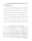
CC1110常用寄存器
位名
复位值
操作性
描述
7
EA
0
R/W
使能所有中断
0关闭所有中断
1每个中断源可以独立的通过与之相关的使能位打开或关闭
6
0
R/W
没有使用
5
STIE
0
R/W
定时器中断使能
0中断关闭
1中断使能
4
ENCIE
0
R/W
AES加密/解密中断使能
0中断关闭
1中断使能
3
URX1IE/
I2SRXIE
0
RW
USART1 RX中断使能/I2S RX中断使能
IRCON.UTX1IF
15
端口1输入
P1INT
0x7B
IEN2.P1IE
IRCON2.P1IF
16
RF通用中断
RF
0x83
IEN2.RFIE
S1CON.RFIF
17
看门狗在定时器模式溢出
WDT
0x8B
IEN2.WDTIE
IRCON2.WDTIF
中断综述
IEN0(0xA8)--Interrupt Enable 0 Register中断使能0寄存器
32kHZ时钟振荡器选择。当这个位被改变,系统时钟源(CLKCON.OSC)必须是HS RCOSC。
032.768kHz晶体振荡器
1低功耗RC振荡器(32-36kHz)
注意:在PM2和PM3模式时这个位将不被保留。从这个模式重新返回到激活模式,这个位将被复位1.
6
OSC
1
R/W
系统时钟振荡器选择
0高速晶体振荡器
所有的中断请求将清除这个位,CC1110Fx将进入到激活模式
- 1、下载文档前请自行甄别文档内容的完整性,平台不提供额外的编辑、内容补充、找答案等附加服务。
- 2、"仅部分预览"的文档,不可在线预览部分如存在完整性等问题,可反馈申请退款(可完整预览的文档不适用该条件!)。
- 3、如文档侵犯您的权益,请联系客服反馈,我们会尽快为您处理(人工客服工作时间:9:00-18:30)。
Copyright © 2014 Huawei Technologies Co., Ltd. All rights reserved.
Page 4
命令行视图
用户视图
系统视图
查看运行状态或其他参数
配置设备的系统参数等
接口视图
……
<Huawei> Warning: Auto-Config is working. Before configuring the device, stop Auto-Config. If you perform configurations when Auto-Config is
running, the DHCP, routing, DNS, and VTY configurations will be lost.
Page 9
配置系统时钟
命令 clock timezone clock datetime clock daylight-saving-time 功能 设置所在时区 设置当前时间和日期 设置采用夏时制
<Huawei>clock timezone BJ add 08:00:00 <Huawei>clock datetime 10:20:29 2013-04-11 <Huawei>display clock 2013-04-11 10:20:48 Thursday Time Zone(BJ) : UTC+08:00
Copyright © 2014 Huawei Technologies Co., Ltd. All rights reserved.
Page 5
命令行功能
命令 CTRL+A CTRL+C CTRL+Z CTRL+] 功能 把光标移动到当前命令行的最前端 停止当前命令的运行 回到用户视图 终止当前连接或切换连接
配置用户界面命令
命令 idle-timeout screen-length history-command max-size 功能 设置超时时间 设置指定终端屏幕的临时显示行数 设置历史命令缓冲区的大小
# Set the size of the history command buffer to 20. <Huawei>system-view [Huawei]user-interface console 0 [Huawei-ui-console0]history-command max-size 20 # Set the timeout duration to 1 minute and 30 seconds. [Huawei-ui-console0]idle-timeout 1 30
Copyright © 2014 Huawei Technologies Co., Ltd. All rights reserved.
Page 16
总结
华为网络设备支持多少个用户同时使用console口登录? 在使用命令interface loopback interface 0 之后,loopback 0接口的状 态是什么?
Copyright © 2014 Huawei Technologies Co., Ltd. All rights reserved.
Page 11
命令等级
用户等级 0 1 2 3-15 命令等级 0 0 and 1 0,1 and 2 0,1,2 and 3 名称 访问级 监控级 配置级 管理级
# Set the user level on the VTY0 user interface to 2. <Huawei>system-view [Huawei]user-interface vty 0 [Huawei-ui-vty0]user privilege level 2 [Huawei-ui-vty0-4]set authentication password cipher huawei
Page 8
基本配置步骤
命令 sysstem-view Enter system view, return user view with Ctrl+Z.
[Huawei]sysname RTA
[RTA]
Copyright © 2014 Huawei Technologies Co., Ltd. All rights reserved.
Page 6
命令行功能
命令 Backspace 功能 删除光标左边的第一个字符
← or Ctrl+B
→ or Ctrl+F TAB
光标左移一位
光标右移一位 输入一个不完整的命令并按TAB键,就可以补全该命令
[Huawei]inter
//TAB
[Huawei]interface
Copyright © 2014 Huawei Technologies Co., Ltd. All rights reserved.
Copyright © 2014 Huawei Technologies Co., Ltd. All rights reserved.
Page 10
配置标题消息
命令 header login header shell 功能 配置在用户登陆前显示的标题消息 配置在用户登陆后显示的标题消息
[Huawei]header login information "welcome to huawei certification!" [Huawei]header shell information "Please don't reboot the device!" …… welcome to huawei certification! Login authentication Password: Please don't reboot the device! <Huawei>
Copyright © 2014 Huawei Technologies Co., Ltd. All rights reserved. Page 14
配置登陆权限
命令 user privilege set authentication password 功能 配置指定用户界面下的用户级别 配置本地认证密码
学完本课程后,您应该能:
掌握VRP命令行的基础知识
利用VRP命令行进行基本的配置
Copyright © 2014 Huawei Technologies Co., Ltd. All rights reserved.
Page 3
设备初始化启动
BIOS Creation Date : Jan DDR DRAM init : OK Start Memory Test ? ('t' or 'T' is test):skip Copying Data : Done Uncompressing : Done …… Press Ctrl+B to break auto startup ... 1 Now boot from sd1:/, 5 2013, 18:00:24
Copyright © 2014 Huawei Technologies Co., Ltd. All rights reserved.
Page 15
配置接口IP地址
RTA 10.0.12.1/24 G0/0/0 G0/0/0
RTB 1.1.1.1/32
# Configure an IP address 10.0.12.1/24 and an IP address 1.1.1.1/32 for LoopBack0. <Huawei>system-view [Huawei]interface gigabitethernet 0/0/0 [Huawei-GigabitEthernet0/0/0]ip address 10.0.12.1 255.255.255.0 [Huawei-GigabitEthernet0/0/0]interface loopback 0 [Huawei-LoopBack0]ip address 1.1.1.1 32
Copyright © 2014 Huawei Technologies Co., Ltd. All rights reserved.
Page 17
谢谢
配置接口参数
协议视图
配置路由协议
<Huawei>system-view Enter system view, return user view with Ctrl+Z. [Huawei]interface GigabitEthernet 0/0/0 [Huawei-GigabitEthernet0/0/0]
<Huawei>system-view [Huawei]user-interface vty 0 4 [Huawei-ui-vty0-4]
VTY 接口最大可配范围为0-14。
Page 13
Copyright © 2014 Huawei Technologies Co., Ltd. All rights reserved.
命令行基础
HUAWEI TECHNOLOGIES CO., LTD.
前言
熟悉VRP命令行并且熟练掌握VRP配置是高效管理华为网络设备的必备基
础。
Copyright © 2014 Huawei Technologies Co., Ltd. All rights reserved.
Page 2
学习目标
<Huawei> system-view [Huawei]command-privilege level 3 view user save