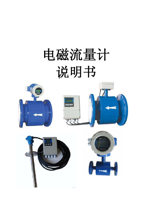
电磁流量计操作指南说明书
电磁流量计FMG90B系列操作手册说明书

FMG920B-SS-VO-NPTFMG90B Series- 2 -FMG90B SeriesTechnical changes reserved- 3 -Table of contents page0 About this operating manual ...................................................................................... 4 1 Device description ..................................................................................................... 5 1.1 Delivery, unpacking and accessories ...................................................................... 5 1.2 Intended use............................................................................................................ 6 1.3 Exclusion of liability ................................................................................................. 6 2 Safety instructions ..................................................................................................... 7 3 Construction and function .......................................................................................... 8 4 Installation of FMG90B .............................................................................................. 9 4.1 Installation instructions ............................................................................................ 9 4.2 Assembly ............................................................................................................... 10 5 Electrical connection ................................................................................................ 11 5.1 Wirings .................................................................................................................. 12 6 Commissioning and measuring operation ............................................................... 13 6.1 Commissioning ...................................................................................................... 13 6.2 Switching on and off .............................................................................................. 13 6.3 Measuring operation .............................................................................................. 13 7 Maintenance and cleaning ....................................................................................... 14 8 Disassembly and disposal ....................................................................................... 15 9 Technical data ......................................................................................................... 16 9.1 Characteristics FMG90B ....................................................................................... 16 9.2 Materials table ....................................................................................................... 17 9.3 Pressure drop ........................................................................................................ 18 9.4 Dimensions (20)Copyright notice:The reproduction, distribution and utilization of this operating manual as well as the communication of its contents to others without express authorization is prohibited. Offenders will be held liable for the payment of damages. All rights reserved in the event of the grant of a patent, utility model or design.About this operating manual Series FMG90B- 4 -0 About this operating manual• The operating manual is aimed at specialists and semi-skilled personnel.•Before each step, read through the relevant advice carefully and keep to the specified order.• Thoroughly read and understand the information in the section “Safety instructions”. If you have any problems or questions, please contact your supplier or contact us directly at:Tel: (203) 359-1660 e-mail:**************Hazard signs and other symbols used:WARNING! / CAUTION! Risk of injury!This sign indicates dangers that cause personal injuries that can lead to health defects or cause considerable damage to property.CAUTION! Electric current!This sign indicates dangers which could arise from handling of electric current.CAUTION! Material damage!This sign indicates actions which could lead to possible damage to material or environmental damage.ADHERE TO OPERATING MANUAL! NOTICE!This symbol indicates important notices, tips or information. NO DOMESTIC WASTE!The device must not be disposed of together with domestic waste.Pay attention to and comply withinformation that is marked with this symbol. Follow the specified instructions and steps.Adhere to the given order.❑ Check the specified points or notices.Reference to another section, document orsource. • Item.FMG90B Series Device descriptionTechnical changes reserved - 5 -1 Device descriptionThe FMG90B series from Omega is a flow sensor without moving parts. The measurement is performed using magnetic induction.The FMG90B is used for measuring or metering water and electrically conductive fluids. The compact design and independence from the intake and discharge sections allows the FMG90B to be used under a variety of conditions.Versions:The FMG90B is available in different inner diameters from 0.12 in to 0.98 in. Type plate:You can find the type plate on the back of the FMG90B. It contains the most important technical data.1.1 Delivery, unpacking and accessoriesAll units have been carefully checked for their operational reliability before shipment. ❒ Immediately after receipt, please check the outer packaging for damages or any signs ofimproper handling.❒ Report any possible damages to the forwarder and your responsible sales representative.In such a case, state a description of the defect, the type and the serial number of the device.Report any in-transit damage immediately. Damage reported at a later date shall not be recognized. Unpacking:Carefully unpack the unit to prevent any damage.Check the completeness of the delivery based on the delivery note. Scope of delivery:❒ 1x FMG90B according to the order data. ❒ 1x Operating manual.IMPORTANT!Use the type plate to check if the delivered unit corresponds to your order.In particular, for devices with electrical components, check to see if the correct power supply voltage is specified.Device descriptionFMG90B Series- 6 -Accessories:❒ Connection cable with molded M12x1 coupling socket. ❒ M12x1 coupling socket as component.1.2 Intended useThe magnetic inductive flow sensor FMG90B must only be used for measuring and metering liquids with a minimum conductivity of 20 μS/cm.WARNING! No safety component!The magnetic inductive flow sensor of the FMG90B series is no safety component in accordance with Directive 2006/42/EC (Machine Directive). Never use the FMG90B as a safety component.The operational safety of the device supplied is only guaranteed by intended use. The specified limits (♑ § 9 "Technical data") may under no circumstances be exceeded.Before installing the device, check that the wetted materials of the device are compatible with the media being used (♑ § 9 “Technical data”).Measuring tube empty (or partially filled). / Conductivity too low.The green LED may blink irregularly if the measuring tube of the FMG90B is empty or partially filled or if the conductivity of the fluid being used is too low. Random pulses will be present at the output, but they do not represent an actual flow.Ensure that the measuring tube of the FMG90B is always completely filled (♑ § 4.1 "Installation instructions").Ensure that the conductivity of the fluid is at least 20 μS/cm.1.3Exclusion of liabilityWe accept no liability for any damage or malfunctions resulting from incorrect installation, inappropriate use of the device or failure to follow the instructions in this operating manual.FMG90B Series Safety instructionsTechnical changes reserved - 7 -2Safety instructionsBefore you install the FMG90B, read through this operating manual carefully. If theinstructions contained within it are not followed, in particular the safety guidelines, this couldresult in danger for people, the environment, and the device and the system it is connected to.The FMG90B corresponds to the state-of-the-art technology. This concerns the accuracy, the operating mode and the safe operation of the device.In order to guarantee that the device operates safely, the operator must act competently andbe conscious of safety issues.OMEGA provides support for the use of its products either personally or via relevant literature. The customer verifies that our product is fit for purpose based on our technical information. The customer performs customer- and application-specific tests to ensure that the product is suitable for the intended use. With this verification all hazards and risks aretransferred to our customers; our warranty is not valid. Qualified personnel:The personnel who are charged for the installation, operation and maintenance of theFMG90B must hold a relevant qualification. This can be based on training or relevanttuition.The personnel must be aware of this operating manual and have access to it at all times.The electrical connection should only be carried out by a fully qualified electrician. General safety instructions:In all work, the existing national regulations for accident prevention and safety in theworkplace must be complied with. Any internal regulations of the operator must also becomplied with, even if these are not mentioned in this manual. Degree of protection according to EN 60529:Please ensure that the ambient conditions at the site of use does not exceed the requirements for the stated protection rating (§ 9 "Technical data"). Prevent freezing of the medium in the device with appropriate measures.Only use the FMG90B if it is in perfect condition. Damaged or faulty devices must be checked without delay and, if necessary, replaced.When fitting, connecting and removing use only suitable appropriate tools.Do not remove or obliterate type plates or other markings on the device, as otherwise thewarranty is rendered null and void. Special safety instructions:Crystallizing liquids:Liquids which crystallize when dried out can cause a malfunction of the FMG90B. Make sure that the FMG90B is not run dry.Prevent the crystallization of the fluid in the device by taking appropriate measures.Further warnings that are specifically relevant to individual operating procedures or activities can be found at the beginning of the relevant sections of this operating manual.Construction and function FMG90B Series- 8 -3 Construction and functionComponents:① Housing:The Housing consists of plastic and has the IP65 degree of protection.② Electrical connection:The electrical connection is made via 4-pin plug M12x1.③ Operation / flow indicator LED.④ Process connection:The process connections are available in different sizes.Construction:The measuring tube with its grounding sleeves and electrodes passes through the housing and forms the external process connection of the FMG90B.A magnetic field for the measurement process is generated inside the housing, which also contains the sensor and signal conditioning circuitry.The two stainless steel electrodes are located in the middle of the measuring tube between the grounding sleeves.The FMG90B does not need any moving parts to make measurements. The inside of the measuring tube is completely open, allowing the fluid to flow unhindered through the measuring tube.Function:The magnetic inductive flow sensor functions according to the induction principle. A DC voltage is generated by the movement of a conductor in a magnetic field:The measuring tube of the FMG90B is located in a magnetic field (B).An electrically conductive medium (V) flows through the measuring tube. The positive and negative charge carriers are oppositely deflected.A voltage (U) is generated at right angles to the magnetic field, which is picked up by the two electrodes.Thereby, the induced voltage is proportional to the average flow velocity of the liquid.The electronics of the FMG90B converts the induced voltage into a flow-proportional frequency signal.FMG90B Series Installation of FMG90BTechnical changes reserved - 9 -4 Installation of FMG90BBefore installing, check that❒ the wetted materials of the device are suitable for the media being used( § 9 “Technical data”).❒ the equipment is switched off and is in a safe and de-energized state. ❒ the equipment is depressurized and has cooled down.SUITABLE TOOLS:Use only suitable tools of the correct size.4.1 Installation instructionsCAUTION! Risk of malfunction due to external magnetic fields! Magnetic fields close to the device can cause malfunctions and should be avoided.Ensure that no external magnetic fields are present at theinstallation site of the FMG90B.•The FMG90B can always be installed anywhere along the pipeline. However, straight sections of piping are preferable.Bubble-formation / run empty possibleDirt deposits possibleRun empty possibleDirt deposits possibleInstallation of FMG90BFMG90B Series• Installation can occur in horizontal and vertical pipes. The flow sensor is only suitable for application in completely filled pipe systems.•As a matter of principle magnetic inductive flow sensors are widely independent from the flow profile. An inlet section is not absolutely necessary.To reach a most highly accuracy of the measurement, you should use straight inlet and outlet sections according to the inner diameter. The inlet section has to be at least10 x inner diameter; the outlet section 5 x inner diameter in order to achieve the specified accuracy.•The inlet and outlet sections and the gaskets must have the same or a slightly larger inside diameter than the measuring tube in order to achieve the specified accuracy.•If two or more FMG90B devices are used side by side, maintain a separation of at least 1.0 in between adjacent devices.If adjacent devices are too close together, operation of both devices may be impaired due to mutual interference.4.2 AssemblyThe FMG90B is installed directly into the pipeline. The compact design and light weight of the unit make wall-mounting unnecessary.IMPORTANT NOTICES:• Only use suitable gaskets for installation.• Observe the flow direction indicated on the type plate. • Observe the mounting dimensions (♑ § 9.3 “Dimensions”).Select an appropriate location for installation(♑ § 4.1 "Installation instructions").To ensure the best possible measuring accuracy, a vertical installation position with increasing flow is preferable (no collecting of dirt deposits).Wrap the FMG90B connections with 1 to 2 wraps of threadtape (e.g. Teflon ® tape). Wrap tape in a clockwise direction, viewed form the end, leaving the first two threads uncovered. Make sure the tape does not intrude into the flow path.Attach the FMG90B with arrow pointed in the direction of flow. The fittings should be screwed into FMG90B hand tight.CAUTION! Material damage! Maximum torque 3.7 ft lb.While tightening, counter the FMG90B only by hand!If you use an open-end or a pipe wrench, the FMG90B can be damaged.To tighten the FMG90B, use an open-end or a pipe wrenchfor the fittings and only the hand for the FMG90B.FMG90B Series Electrical connection 5 Electrical connectionThe electrical connection of the FMG90B is made via the 4-pin plug M12x1 at the top of the housing.The wiring of the FMG90B depends on the ordered version. A distinction is made between frequency output or analog output and frequency output.CAUTION! Electric current!The electrical connection should only be carried out by a fully qualified electrician.De-energize the electrical system before connecting the FMG90B.Connection cable:Suitable connection cables with molded coupling socket M12x1 are available in different lengths as OMEGA accessories. The maximum permissible cable length is 10 m. Connection 4-pin plug M12x1:Screw the coupling socket of the connection cable to the plug of the FMG90B.Tighten the knurled nut of the coupling socket with a maximum torque of 1 Nm.Electrical connection FMG90B Series5.1 WiringsPinout:The pinout differs according to the chosen configuration of the device. Pinout:M12x1Possible pinout: Pin 1: +U BPin 2: n. c. (not connected) / Analog U/I Pin 3: GNDPin 4: FrequencyConnect the connection cable according to your version and the pinout on the type plate.Supply voltage:FMG90B with frequency output:Push-Pull:NPN Open Collector:PNP Open Collector:*1: Push-Pull switching outputs of several FMG90B may not be connected in parallel. *2: Recommendation Pull-Up / Pull-Down resistance R L ~2.5 k Ω (12 V) or ~5 k Ω (24 V). Ensure that the maximum signal current of 25 mA is not exceeded.Use of frequency and analog outputRecommendation for resistance R L ~2.5 k Ω (12 V) or ~5 k Ensure that the maximum signal current of 25 mA is not exceeded.FMG90B Series Commissioning and measuring operation6 Commissioning and measuring operationBefore switching on the FMG90B for the first time, please follow the instructions in the following section.6.1 CommissioningCheck that❒ the FMG90B has been installed correctly and that all screw connections are sealed. ❒ the electrical wiring has been connected properly. ❒ the measuring system is vented by flushing.6.2 Switching on and offThe FMG90B has no switch and cannot be switched on or off on its own. Switching on and off is carried out by the applied supply voltage. Switch on the supply voltage.The green LED lights up. The FMG90B is ready and goes into measuring mode.6.3 Measuring operationIn the measuring mode, the green LED flashes proportional to the measured flow.For the human eye, the flashing is no longer visible from a frequency of ~30...40 Hz.The green LED then seems to light up permanently.FMG90B with frequency output:The FMG90B provides according to the version a flow proportional NPN, PNP or Push-Pull square wave signal.The frequency of the pulse output changes according to the flow ( Fig.).FMG90B with analog output:According to the configuration of the FMG90B, the analog output provides a voltage or current signal.This signal is proportional to the measured flow. You will find the scaling of the analog output on the type plate.Maintenance and cleaning FMG90B Series7 Maintenance and cleaningMaintenance:The FMG90B is maintenance-free and cannot be repaired by the user. In case of a defect, the device must be replaced or sent back the manufacturer for repair.CAUTION! Material damage!When opening the device, critical parts or components can be damage. Never open the device and perform any repair yourself.Cleaning:Clean the FMG90B with a dry or slightly damp lint-free cloth. Do not use sharp objects or aggressive agents for cleaning.FMG90B Series Disassembly and disposal 8 Disassembly and disposalCAUTION! Risk of injury!Never remove the device from a plant in operation.Make sure that the plant is shut down professionally.Before disassembly:Prior to disassembly, ensure that❒the equipment is switched off and is in a safe and de-energized state.❒the equipment is depressurized and has cooled down.Disassembly:Remove the electrical connectors.Removethe FMG90B using suitable tools.Disposal:NO HOUSEHOLD WASTE!The FMG90B consists of various different materials. It must not be disposed of with household waste.Take the FMG90B to your local recycling plant.Technical data FMG90B Series9 Technical dataThe technical data of customized versions may differ from the data in these instructions. Please observe the information specified on the type plate.9.1 Characteristics FMG90B** Voltage output 0.5…10 V only available with 16…24 VDCFMG90B Series Technical data 9.2 Materials table* Available for FMG93B, FMG96B, FMG98BTechnical data FMG90B Series9.3Pressure dropFMG93BFMG96BFMG98B0.00.51.01.52.02.53.00.10.20.30.40.50.6P r e s s u r e d r o p ∆p [p s i ]Flow rate Q [GPM]0.00.51.01.52.02.50.250.50.7511.251.5P r e s s u r e d r o p∆p [p s i ]Flow rate Q [GPM]0.000.501.001.50123456P r e s s u r e d r o p ∆p [p s i ]Flow rate Q [GPM]FMG90B Series Technical dataFMG915B FMG920B FMG925B0.0000.1250.2500.3750.500024******** Pressuredrop∆p[psi]Flow rate Q[GPM]0.00.51.01.52.0010********Pressuredrop∆p[psi]Flow rate Q[GPM]0.00.10.20.30.40.5010203040506070 Pressuredrop∆p[psi]Flow rate Q[GPM]Technical data FMG90B Series9.4 DimensionsFMG90B:FMG925B:FMG90B Series For your notes For your notesFor your notes FMG90B Series For your notesM5759/0220FMG920B-SS-VO-NPT。
电磁流量计说明书
电磁流量计说明书目录一、产品概述二、工作原理三、产品特点四、外形尺寸五、流量选型及安装六、流量计接线图七、按键说明与菜单调试八、故障分析与排除九、电磁流量计电极内衬选择表一、产品概述智能电磁流量计是我公司采用先进技术研制、开发与生产的液体流量测量仪表,具有高精度、高可靠性与使用寿命k等优点。
为确保产品质量,我公司在设计产品结构、选材、制定工艺、生产装配与出厂测试等过程中,对每个环节细致研究与控制,并配套完整的流量标定检测系统。
产品执行标准:JB/T 9428-1999。
二、工作原理智能电磁流量计测量原理是基于法拉第电磁感应定律。
即当导电液体流过电磁流量计时,导体液体中会产牛与平均流速V(体积流量)成正比的电压,其感应电压信号通过两个与液体接触的电极检测,通过电缆传至放大器,然后转换成统一的输出信号。
基于电磁流量计的测量原理,要求流动的液体具有最低限度的电导率。
图1:结构原理图E=KBDK:比例常数B:磁感应强度D:测量管内径V:测量管截面的平均流速图2:信号流程图三、产品特点★低频三值矩形波恒流励磁,不受工频及现场各种杂散干扰的影响,性能稳定可靠。
★采用非均匀磁场的新技术及特殊磁路结构,磁场稳定可靠,且缩小了体积,减轻了重量,使流量计具有小型轻量化的特点。
★具有空管自动检测与电路处理功能。
★可根据用户实际需求现场在线修改量程。
★测量管内无阻流件,因此无附加压力损失。
★测量结果与液体的压力、温度、密度、粘度、电导率(小小于最低电导率)等物理参数无关。
★直管段相对要求较短★使用方便,安装后只需接上电源,不需其它任何操作,即可输出标准信号,便于非专业人员使用。
性能数据衬里及公称通径DN(mm):橡胶衬电:40,50,65,80,100,125,150,200,250,300,350,400,450,500,600,700,800. 900. 1000. 1200. 1400, 1600. 1800. 2000. 2200四氟衬里:10,15,20,25,32,40,50,65,80,100,125,150,200,250,300,350,400, 450. 500. 600. 700. 800. 900. 1000. 1200, 1400. 1600, 1800. 2000. 2200 注:特殊规格可订制测量误差:±0.5%、±1.0%、±1.5.被测介质温度:氯橡胶衬咀:-20℃~+65℃,聚四氟乙烯:-30℃~+180℃,聚氯脂橡胶:-20℃~+80℃,聚丙烯:-20℃~ +100℃环境温度:-25 ~+45℃相对湿度:5% - 95%额定压力:DN10-DN80: 4.0MPa DN100-DN150: 1 .6MPa DN200-DN1000: 1 .0Mpa DN1200-DN2000: 0.6MPa DN2200:0.25MPa流速范围:0. 3-12m/s电导率:被测流体电导率不小于5us/cm输出信号及负载电阻:0-10mADC,0-1000nΩ输出频率上限:l~ 5000Hz没定4-20rnADC,0-500 Ω具有防雷击保护串行通讯:可选RS232C或RS485脉冲输出上限5000CP/S;脉冲当量为0.0001~1.0 m3/CP;脉冲宽度:自动设置20ms或方波电级材料:含不锈钢(M02Ti)、钛(Ti)、钽(Ta)、哈氏合金(HB)、铀(Pt)防护等级:标准IP65、IP67、可选IP68直管段长度:上游≥10DN,下游≥5DN连接方式:管道法兰连接,符合标准:GB9119-88功耗:<25W供电电源:220V AC±10%,50HZ±5%、24VDC直流供电产品分类:管道式电磁流量计分一体型和分体型一体型分体型四、外形尺寸4.1产品的外形图34.2产品安装尺寸4.2.1平法兰型电磁流量计(含传感器的)外形及连接尺寸:(见图4、表1)图4表1平法兰型传感器连接尺寸和连接法兰安装尺寸(mm)4.2.2凹凸环槽法兰型电磁流量计(含传感器的)外形及连接尺寸(表2)表2凹凸环槽法兰型与管道连接尺寸:(mm)4.2.3螺纹连接型电磁流量计(含传感器的)外形及连接尺寸(表3)表3螺纹连接型与管道连接尺寸(mm)五、流量选型及安装如何选型正确选用电磁流量计是保证用好电磁流量计的前提条件,选用什么种类的电磁流量计应根据被测液体介质的物理性质和化学性质而决定。
电磁流量计_说明书
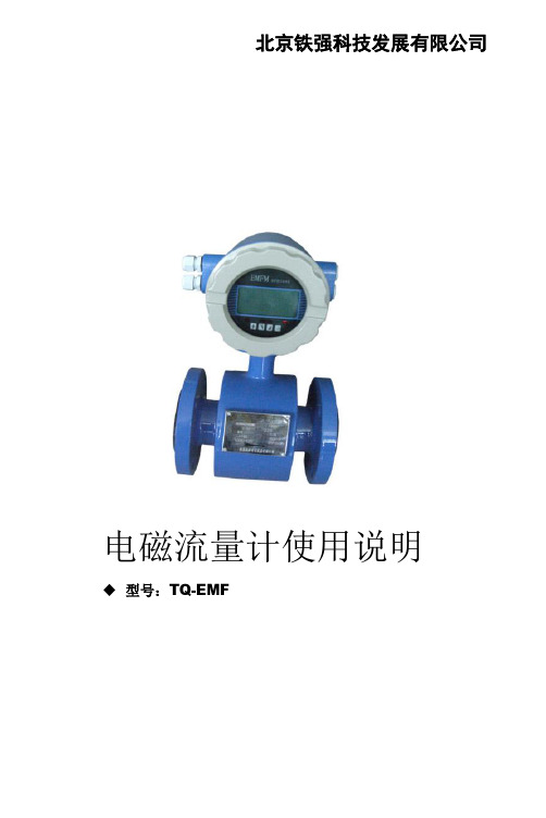
北京铁强科技发展有限公司电磁流量计使用说明型号:TQ-EMF→注重仪器仪表事业的繁荣与发展←工作原理工作原理基于法拉第电磁感应定律。
即当导电液体渡过电磁流量计时,导体中会产生感应电动势,其感应电动势与导电液体流速、磁感应强度、导体宽度(流量计内径)成正比。
该感应电动势由流量计管壁上的一对电极检测到,通过运算就可以得到流量。
感应电动势议程为:E=D·V·B其中:E:感应电动势 D:测量管内径 V:流速 B:磁感应强度为了获得满意的测量精度,必须满足以下条件:(一)被测液体必须具有导电性;(二)液体必须充满管道;(三)液体成分必须均匀;(四)如果液体导磁,流量计磁场将改变,必须对流量计进行修正。
1北京铁强科技发展有限公司2口径10-3200口径10-3200励磁方式 双向恒流方波励磁 励磁方式 双向恒流方波励磁 安装形式 一体型 安装形式 分体型 衬里 氯丁橡胶,PTFE衬里 氯丁橡胶,PTFE电极材料316L ,HC ,HB ,钛,钽,铂铱电极材料SVS316L ,HC ,HB ,钛,钽,铂铱接地 内置接地电极 接地 内置接地电极 介质 导电性液体 介质 导电性液体 精确度等级 0.2, 0.5, 1.0 精确度等级 0.2, 0.5, 1.0 介质电导率 >5μS/cm 介质电导率 >5μS/cm 防爆等级ExdIICT6防爆等级 ExdIICT6 管道连接法兰 GB9119-2000或GB9115-2000管道连接法兰GB9119-2000 或GB9115-2000 管道连接 法兰连接管道连接 法兰连接介质温度氯丁橡胶:-10℃~+60℃; PTPE:-10℃~+120℃介质温度氯丁橡胶:-10℃~+60℃; PTPE:-10℃~+120℃额定压力 4 MPa,1.6 MPa, 1.0 MPa 额定压力 4 MPa,1.6 MPa, 1.0 MPa 防护类别 IP65,IP68防护类别 IP65,IP68输出信号4-20mA 电流,脉冲,上下限报警输出信号4-20mA 电流,脉冲,上下限报警电缆接口 G1/2内螺纹 电缆接口 G1/2内螺纹 通讯 RS485通讯协议通讯 RS485通讯协议显示器显示瞬时流量,百分比,流速,正反向累积流量和总累积量显示器显示瞬时流量,百分比,流速,正反向累积流量和总累积量电源 220V AC ,24V DC 电源 220V AC ,24V DC 使用类型 一般型,防水型 使用类型 一般型,防水型 *高压定做*高压定做特点:● 提高了流量测量的稳定性 ● 快速响应和高稳定性,甚至对于高浓度浆和低电导率液体也如此→注重仪器仪表事业的繁荣与发展←●高可靠性电极结构●通径从10mm到3200mm●交、直流电源均可使用●多功能智能转换器●断电时,EEPROM可保护设定参数和累积值●高清晰度LCD背光显示技术指标电磁流量转换器部件技术指标输入信号:来自检测器的与流量成正比的信号输出信号:4-20mA DC(负载电阴0-750)通过参数设定选择肪冲/报警输出脉冲输出/报警输出:(额定值:30VDC,200mA)通信信号(选择功能)电脑通信信号(叠加在4-20mA DC信号上)负载电阴:205-600(包括电缆电阻)负载电容:最大0.22μF负载电感:最大3.3mH电缆线间距:≥15cm(以避免平行布线)接收仪表的输入的阴抗:≥10K(在2.4Hz时)最大电缆长度:2Km(使用“CEV”电缆时)量程范围设定功能:●通过设定体积单位,流量值和流量计通径来设定体积流量●体积单位:m³●速度单位:m/s●流量计通径:mm●瞬时流量显示功能:显示流量单位显示,也显示量程百分比●累积流量显示功能:可以显示正、反向累积值和总累积值●脉冲输出功能:通过设定一个脉冲系数就可以输出代表任何流量单位所表示的脉冲量●脉冲宽度:占空比50%或固定脉冲宽度供用户选择●输出速率:10-400(脉冲数/秒)(只有在选择脉冲输出方式时使用)3北京铁强科技发展有限公司●失电数据保护:由EEPROM贮存数据,无需备用电池●正、反流量测量功能:在正、反流向测量模式中,可以测量反向流量●上限报警:流量大于上限设定值●下限报警:流量小于下限设定值●阴尼功能:可设定范围从0.2秒-100秒(63%响应时间)正常工作条件:环境温度:-20~60℃电源电压的额定值:220VAC型:100V~240V ACDC型:24V DC安装和结构:安装:分离型:转换器,50mm管道或平面安装组合型:与传感器装成一体导线连接口:ISO M20×1.5内螺纹接线端子:M3螺钉壳体材料:铝合金结构:一般型:防护等级IP65防水型:(IP68)如何正确选型:流量计的选型是仪表应用中非常重要的工作,据有关资料表明,仪表在实际应用中有2/3的故障是仪表的错误选型和错误的安装而造成的,请特别注意。
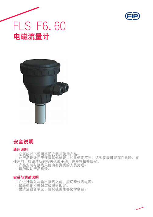
FLS F6.60电磁流量计安全说明说明书
FLS F6.60电磁流量计安全说明通用说明• 必须按以下说明手册安装并使用产品。
• 此产品设计用于连接其他仪表,如果使用不当,这些仪表可能存在危险。
在使用前,应阅读所有相关仪表手册,并遵守相关规定。
• 产品安装与接线只能由有资质的人员完成。
• 请勿改动产品构造。
安装与调试说明• 在进行输入与输出接线之前,应切断仪表电源。
• 仪表使用不得超过极限值规定。
• 要清洁设备单元,请只使用兼容化学制品。
包装清单请核实产品完整,并且没有任何损坏。
必须包含以下物品:• F6.60 电磁流量计• F6.60 电磁流量计说明手册• 带接口软件的 USB 笔式驱动器• 用于仪表/电脑接口的 USB 电缆说明新型 FLS F6.60 是一种无移动机械部件的流量计,可以用于测量具有导电性的匀质污染液体。
F6.60可以提供三种不同的选项:与FLS流量监视器相连的频率输出,长距离传输和PLC连接的4-20mA输出,以及新的可自由设置的体积脉冲输出。
F6.60插入型电磁流量计装有USB接口和完整专用软件(可从FLS网站免费下载),可以通过电脑按照特殊的安装要求轻松设置所有参数(例如满刻度和截止参数)。
此特定设计可以在DN15(0.5”) - DN600(24”)的宽范围管道尺寸内实现精确的流量测量。
技术数据通用• 管道尺寸范围:DN15 至 DN600(0.5”至 24”)• 最大流量范围:0.05 - 8m/s(0.15 - 26.24 ft./s)• 满量程:8 m/s (26.24 ft/s)• 线性:读数的± 1% + 1.0 cm/s• 可重复性:读数的± 0.5%• 外壳:IP65• 材料:- 箱体:PC/ABS- 垫片:EPDM• 焊接材料:- 传感器本体:316L SS/PVDF;316L SS/PEEK;CuNi合金/PVDF- O形圈:EPDM或FPM- 电极:316L SS 或 CuNi 合金电气• 电源:- 12 - 24VDC±10% 稳压(逆极性和短路保护)- 最大电流:消耗量:250 mA- 保护性接地:< 10 Ω• 电流输出:- 4-20 mA,隔离- 最大环路阻抗:800Ω(24VDC)- 250Ω(12VDC)- 正流量指示或负流量指示• 固态继电器输出:- 用户可选择:最小值警报、最大值警报、体积测定、脉冲输出、窗口警报、关闭- 光隔离,50mA最大漏电流,24VDC最大上拉电压- 最大脉冲/分钟:300- 迟滞:用户可选择• 开路集电极输出(频率):- 类型:开路集电极NPN- 频率:0 – 800 Hz- 最大上拉电压:24 VDC- 最大电流:50 mA,限流- 与FLS M9.02、M9.03、M9.50兼容• 开路集电极输出(方向):- 类型:开路集电极NPN- 最大上拉电压:24 VDC- 最大电流:50mA,限流- 电流方向:0 VDC 箭头方向+ VDC 箭头反向环境• 存储温度:-30°C - +80°C(-22°F - 176°F)• 环境温度:-20°C - +70°C(-4°F - 158°F)•相对湿度:0 - 95%(无结露)• 液体条件:- 均质液体、糊剂或料浆,还有固体成份- 最小电导率:20 μS- 温度:PVDF底部版本:-10°C - +60°C(14°F - 140°F)PEEK底部版本:-10°C - +150°C(14°F - 302°F)• 最大工作压力:- 16 bar @ 25°C (232 psi @ 77°F)- 8.6 bar @ 60°C (124 psi @ 140°F)标准和认证•按照ISO 9001要求制造•按照ISO 14001要求制造•CE•RoHS合规性•GOST R尺寸A 传感器本体B F6.60 电磁流量计1 O形圈(EPDM 或 FPM)2 传感器本体(316L SS 或 CuNi)3 隔离板(PVDF 或 PEEK)4 电极(316L SS 或 CuNi)5 电缆填料盖6 管件内安装使用的 ABS 端帽7 电子盒安装管道位置• 图1中显示的六个最普通的安装配置有助于在管道中为转轮式流量传感器和电磁流量传感器选择最佳位置。
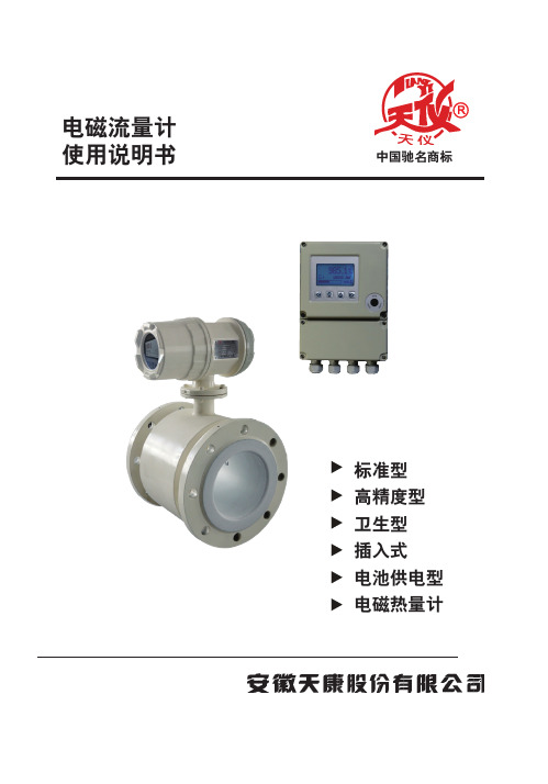
电磁流量计说明书

电磁流量计说明书目录一、产品概述二、工作原理三、产品特点四、外形尺寸五、流量选型及安装六、流量计接线图七、按键说明与菜单调试八、故障分析与排除九、电磁流量计电极内衬选择表一、产品概述智能电磁流量计是我公司采用先进技术研制、开发与生产的液体流量测量仪表,具有高精度、高可靠性与使用寿命k等优点。
为确保产品质量,我公司在设计产品结构、选材、制定工艺、生产装配与出厂测试等过程中,对每个环节细致研究与控制,并配套完整的流量标定检测系统。
产品执行标准:JB/T 9428-1999。
二、工作原理智能电磁流量计测量原理是基于法拉第电磁感应定律。
即当导电液体流过电磁流量计时,导体液体中会产牛与平均流速V(体积流量)成正比的电压,其感应电压信号通过两个与液体接触的电极检测,通过电缆传至放大器,然后转换成统一的输出信号。
基于电磁流量计的测量原理,要求流动的液体具有最低限度的电导率。
图1:结构原理图E=KBDK:比例常数B:磁感应强度D:测量管内径V:测量管截面的平均流速图2:信号流程图三、产品特点★低频三值矩形波恒流励磁,不受工频及现场各种杂散干扰的影响,性能稳定可靠。
★采用非均匀磁场的新技术及特殊磁路结构,磁场稳定可靠,且缩小了体积,减轻了重量,使流量计具有小型轻量化的特点。
★具有空管自动检测与电路处理功能。
★可根据用户实际需求现场在线修改量程。
★测量管内无阻流件,因此无附加压力损失。
★测量结果与液体的压力、温度、密度、粘度、电导率(小小于最低电导率)等物理参数无关。
★直管段相对要求较短★使用方便,安装后只需接上电源,不需其它任何操作,即可输出标准信号,便于非专业人员使用。
性能数据衬里及公称通径DN(mm):橡胶衬电:40,50,65,80,100,125,150,200,250,300,350,400,450,500,600,700,800. 900. 1000. 1200. 1400, 1600. 1800. 2000. 2200四氟衬里:10,15,20,25,32,40,50,65,80,100,125,150,200,250,300,350,400, 450. 500. 600. 700. 800. 900. 1000. 1200, 1400. 1600, 1800. 2000. 2200 注:特殊规格可订制测量误差:±0.5%、±1.0%、±1.5.被测介质温度:氯橡胶衬咀:-20℃~+65℃,聚四氟乙烯:-30℃~+180℃,聚氯脂橡胶:-20℃~+80℃,聚丙烯:-20℃~ +100℃环境温度:-25 ~+45℃相对湿度:5% - 95%额定压力:DN10-DN80: 4.0MPa DN100-DN150: 1 .6MPa DN200-DN1000: 1 .0Mpa DN1200-DN2000: 0.6MPa DN2200:0.25MPa流速范围:0. 3-12m/s电导率:被测流体电导率不小于5us/cm输出信号及负载电阻:0-10mADC,0-1000nΩ输出频率上限:l~ 5000Hz没定4-20rnADC,0-500 Ω具有防雷击保护串行通讯:可选RS232C或RS485脉冲输出上限5000CP/S;脉冲当量为0.0001~1.0 m3/CP;脉冲宽度:自动设置20ms或方波电级材料:含不锈钢(M02Ti)、钛(Ti)、钽(Ta)、哈氏合金(HB)、铀(Pt)防护等级:标准IP65、IP67、可选IP68直管段长度:上游≥10DN,下游≥5DN连接方式:管道法兰连接,符合标准:GB9119-88功耗:<25W供电电源:220V AC±10%,50HZ±5%、24VDC直流供电产品分类:管道式电磁流量计分一体型和分体型一体型分体型四、外形尺寸4.1产品的外形图34.2产品安装尺寸4.2.1平法兰型电磁流量计(含传感器的)外形及连接尺寸:(见图4、表1)图4表1平法兰型传感器连接尺寸和连接法兰安装尺寸(mm)4.2.2凹凸环槽法兰型电磁流量计(含传感器的)外形及连接尺寸(表2)表2凹凸环槽法兰型与管道连接尺寸:(mm)4.2.3螺纹连接型电磁流量计(含传感器的)外形及连接尺寸(表3)表3螺纹连接型与管道连接尺寸(mm)五、流量选型及安装如何选型正确选用电磁流量计是保证用好电磁流量计的前提条件,选用什么种类的电磁流量计应根据被测液体介质的物理性质和化学性质而决定。
电磁流量计说明书

电磁流量计操作使用说明书目录一、操作指南1.基本设置 (5)1.1 流量单位 (5)1.2 流量显示分辨率 (5)1.3 总量单位 (5)1.4 总量显示分辨率 (5)1.5 阻尼时间(s) (5)2.信号处理设置 (6)2.1 刻度流量 (6)2.2 小信号切除% (6)3.脉冲输出设置 (7)3.1 频率上限 (7)3.2 脉冲当量 (7)3.3 脉冲宽度 (7)3.4 脉冲电平 (8)3.5 频率/脉冲输出选择 (8)4.RS485输出设置 (8)4.1 通讯协议选择 (8)4.2 波特率 (8)4.3 数据位 (9)4.4 校验方式 (9)4.5 设备地址 (9)5.累计管理 (9)5.1 清累计 (9)5.2 预置累计 (9)6.仪表校准 (10)6.1 4mA校准 (10)6.2 20mA校准 (10)6.3 零点校准 (10)7.工厂设置 (11)7.1 传感器口径 (11)7.2 转换器系数 (11)7.3 传感器系数 (12)7.4 励磁频率 (12)7.5 低流量报警开关 (12)7.6 高流量报警开关 (12)7.7 空满管检测开关 (12)7.8 高流量报警点% (13)7.9 低流量报警点% (13)7.10 RS485功能开关 (13)7.11 非稳态时间 (13)7.12 响应极限........................................................................................ 1错误!未定义书签。
7.13 响应时间........................................................................................ 1错误!未定义书签。
7.14 保存设置........................................................................................ 1错误!未定义书签。
电磁流量计操作说明书

电磁流量计操作说明书第一章引言电磁流量计是一种用于测量导电液体流量的仪器,其原理基于法拉第电磁感应定律。
本操作说明书旨在帮助用户正确操作电磁流量计,确保其正常运行并获得准确的流量测量结果。
在使用本仪器之前,请仔细阅读本说明书并按照其中的操作步骤进行操作。
第二章仪器概述2.1 外观与结构电磁流量计主体由流量传感器和转换器组成。
流量传感器通常由两个平行的电极和一对辅助电极构成,其中两个平行电极用于产生磁场,辅助电极用于测量电导率。
转换器则负责接收传感器信号并进行处理,最终将流量值输出到显示屏或其他记录设备。
2.2 规格与参数根据不同型号的电磁流量计,规格和参数会有所差异。
在使用前,请查看所购买的电磁流量计的技术手册,了解其具体规格和参数。
第三章安装与调试3.1 安装3.1.1 安装环境电磁流量计的安装环境应满足以下条件:- 温度范围:XX℃至XX℃- 相对湿度:不大于XX%- 安装位置:远离磁场干扰和强电磁波辐射源- 安装方向:尽量保持垂直安装3.1.2 安装步骤根据安装环境特点和流量计型号的不同,具体的安装步骤可能会有所差异。
请按照以下一般步骤进行操作:1) 确保安装环境符合要求。
2) 将流量计与管道连接,确保连接牢固并无泄漏。
3) 连接电磁流量计的电缆至转换器。
4) 检查安装是否正确,确保传感器与管道之间没有间隙或阻塞物。
5) 安装完成后,检查各连接部位是否紧固。
3.2 调试完成安装后,进行如下调试步骤:1) 检查电源线是否连接正确并插入可靠。
2) 按照转换器说明书设置各参数。
3) 打开阀门,使介质流经流量计。
4) 根据需要进行校准,并记录相关参数。
5) 检查转换器显示的流量值是否与实际值一致。
第四章使用与维护4.1 使用注意事项在正常使用电磁流量计时,需注意以下事项:1) 请勿撞击仪器或使用硬物敲打仪器外壳。
2) 请勿让电磁流量计接触强酸、强碱等腐蚀性物质。
3) 请勿将电磁流量计放置在温度过高或过低的环境中。
电磁流量计安装使用说明书
1 安全指南
1 安全指南
1.1 用途
• 本测量设备仅用于测量密闭管道中导电介质的流量。测量去离子水时,介 质的最小电导率为 20 μS/cm。对于大部分液体,测量时需要的最小电导率 可为 5 μS/cm。 • 除本文指定用途外,其它任何用途均会对人员和整个测量系统的安全造成 威胁,禁止使用。 • 制造商对由于不恰当使用或用于非指定用途而引起的损坏不承担责任。
-4-
1000系列电磁流量计 1000系列电磁流量计 2.1工作原理
法拉第感应定律(指的是当导体通过磁场时会在导体内部产生感应电势)即 为电磁流量计测量的基础原理。这种测量原理可应用于具有导电性的流体,该 流体流入磁场垂直于流体方向的管道,在流体中感应生成的电势可利用对称布 置的两个电极进行测量。信号电压UE与磁感应强度B,电极间距D以及流体平均 速度v成正比。由于磁感应强度B与电极间距D为常量,所以信号电压UE与平均 流速v成正比。用于计算体积流速的等式表明信号电压UE与体积流量成线性正 比。
-6-
1000系列电磁流量计 2.4电磁流量计的主要技术参数 2.4.1 标准型和高精度型技术参数
型号
TK1100标准型系列
TK1200高精度系列
口径
DN3-DN2200
DN10-DN1200
精度
0.5%
0.2%,0.3%
安装方式
夹持,法兰
夹持,法兰
重复性 测量范围
0.1% 0-12m/s(流量单位可改变)
-7-
1000系列电磁流量计
2.4.2 卫生型和电池供电型技术参数
型号 口径 精度
TK1300卫生型系列 DN3-DN150 0.2%,0.5%
TK1500电池供电系列 DN10-DN1200 0.5%
- 1、下载文档前请自行甄别文档内容的完整性,平台不提供额外的编辑、内容补充、找答案等附加服务。
- 2、"仅部分预览"的文档,不可在线预览部分如存在完整性等问题,可反馈申请退款(可完整预览的文档不适用该条件!)。
- 3、如文档侵犯您的权益,请联系客服反馈,我们会尽快为您处理(人工客服工作时间:9:00-18:30)。
电磁流量计操作指南说明书
1. 引言
电磁流量计是一种常用的流量测量仪表,广泛应用于工业生产、水处理、石油化工等领域。
本操作指南旨在帮助用户正确操作电磁流量计,提高测量准确性和工作效率。
2. 安装与连接
2.1 安装
根据现场实际情况选择合适的安装位置,确保电磁流量计与被测介质流向一致,并确保安装位置平整、无振动。
安装时应注意保持流量计的垂直放置,并留出足够的空间以便于维修和更换。
2.2 连接
将电磁流量计与管道系统连接,确保连接口紧固可靠,避免泄漏。
请按照电磁流量计与管道连接口的规格选用适当的密封件。
连接完成后,检查连接口是否有松动,若有松动应及时进行重新紧固。
3. 参数设定
在开始测量之前,需进行相关参数的设定,以确保电磁流量计的准确度。
3.1 测量范围
根据被测介质的流量范围,设置电磁流量计的测量范围。
请确保所设置的测量范围能够满足实际测量需求,并预留一定的余量,以防止超量程的发生。
3.2 温度和压力补偿
根据被测介质的实际温度和压力情况,设置电磁流量计的温度和压力补偿参数。
温度和压力补偿能够有效提高测量的准确性,确保测量结果的可靠性。
4. 运行操作
4.1 供电与启动
将电磁流量计与电源进行连接,并确保电源正常供电。
在供电后,按照操作面板上的启动指示进行操作,启动电磁流量计。
4.2 测量显示与记录
在启动后,电磁流量计将实时显示被测介质的流量值。
可以根据需要选择记录仪表或计算机系统进行流量数据的记录与存储,便于后期数据分析和处理。
4.3 异常处理与维护
在日常使用中,若发现电磁流量计的显示异常或其他问题,请及时进行检查和维护。
遇到故障时,应按照设备说明书进行相应的维修操作,或联系售后服务人员进行维修。
5. 注意事项
5.1 防护措施
在安装和操作电磁流量计时,应注意避免其接触任何化学物质,以
防损坏仪表。
同时,应做好防护措施,避免流量计受到外部环境的影响。
5.2 清洁与维护
定期对电磁流量计进行清洁和维护,以保持仪表的良好工作状态。
请使用干净柔软的布进行擦拭,避免使用有腐蚀性或磨损性的清洁剂。
5.3 定期校验
为确保电磁流量计的准确性,建议定期进行校验。
请参考设备说明
书中的校验程序,并按照相关要求进行操作。
6. 常见问题解答
在使用电磁流量计的过程中,常会遇到一些问题。
以下是一些常见
问题的解答,供用户参考:
6.1 为什么电磁流量计的测量结果与实际流量不符?
可能是参数设置不准确,建议重新设置参数。
如果问题依然存在,
可能是仪表故障,建议联系售后服务人员进行维修。
6.2 电磁流量计显示异常怎么办?
可以尝试重新启动电磁流量计,如果问题依然存在,建议检查电源
和连接线路是否正常,或联系售后服务人员进行维修。
7. 结语
本操作指南主要介绍了电磁流量计的操作指南与注意事项。
准确的操作和维护可以确保电磁流量计的工作准确性和使用寿命,希望本指南对用户在使用电磁流量计时有所帮助。
总字数:737字。