SMC真空系统参考文档
SMC气动第三册(真空元件)
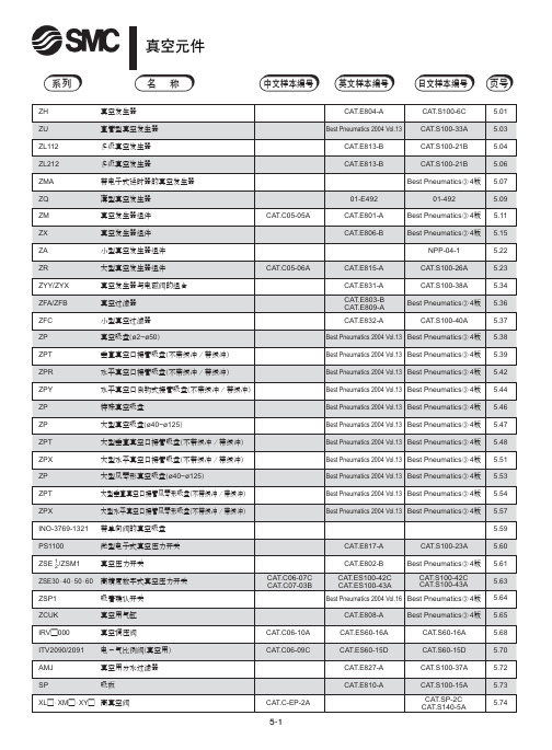
记号 06 08 10 12 01 02 03
尺寸 ø6 ø8 ø10 ø12 Rc 1 8 Rc 1 4 Rc 3 8
形式 快换接头 快换接头 快换接头 快换接头 螺纹拧入 螺纹拧入 螺纹拧入
表① 连接形式的组合
主体形式 盒型 (内置消声器) 直接配管型 (无消声器) ① ② ③ ① ② ③ SUP 快换接头 快换接头 螺纹拧入 快换接头 快换接头 螺纹拧入 VAC 快换接头 螺纹拧入 螺纹拧入 快换接头 螺纹拧入 螺纹拧入 EXH — — — 快换接头 快换接头 螺纹拧入
页号
5.01 5.03 5.04 5.06 5.07 5.09 5.11 5.15 5.22 5.23 5.34 5.36 5.37 5.38 5.39 5.42 5.44 5.46 5.47 5.48 5.51 5.53 5.54 5.57 5.59 5.60 5.61 5.63 5.64 5.65 5.68 5.70 5.72 5.73 5.74
注意
1 配管不能是螺旋状。
真空侧和供给侧都不能出现螺旋状配管, 应尽量短而直。 配管容积增 大则响应时间变长。
2 真空发生器排气侧的配管有效截面积应大。
排气一旦节流,真空发生器的性能就变差。
4 吸入流量过大,则真空开关的设定困难。
几 mm大小的小工件, 一旦选定吸入流量过大的真空发生器, 和未吸 着时的真空压力之差太小, 会使真空压力开关的设定变困难, 故要选 定合适的真空发生器。
注意
1 方向控制阀,速度控制阀等相关元件应参见各自样本的注意 事项。
维护
警告
1 要定期对真空过滤器和消声器进行清洗。
过滤器及消声器的孔眼被堵, 真空发生器的性能便降低。 在粉尘多的 场合,应使用处理流量大的真空过滤器。
ZH ZX 系例SMC真空阀资料

喷嘴直径 05 07 10 13 15 18 20 0.5mm 0.7mm 1.0mm 1.3mm 1.5mm 1.8mm 2.0mm 最高真空度 S L +88kPa +48kPa
构造图
排气口 主体 扩压管
外形尺寸图 (毫米) ZU05S, ZU05L
进口
真空口
ZU07S, ZU07L
快换接头 快换接头
排气特性/流量特性图表 ZU05S
排气特性
( 供给压力在 0.45MPa 的情况下 )
最高真空度: 85kPa
ZU05L
排气特性
空气消耗量
最高真空度: 48kPa
流量特性
流量特性
真空用数字式压力开关规格(可选项)
型号 ZSE4-00-□□-□-X105 ZSE4B-00-□□-□-X105 ZSE4E-00-□□-□-X105 带辅助照明LCD 显示 LCD LED -101~10kPa 压力设定范围 -101~0kPa -101~10kPa 200kPa 最高使用压力 动作指示灯 OUT1:绿色 绿色 (ON时亮) OUT2:红色 200Hz(5ms) 响应频率 可变(3digit以上) 可变(可从0设定) 迟 迟滞模式 固定(3digit) 滞 上下限比较模式 空气·非腐蚀性气体 使用流体 ±3%F.S.以下 温度特性 ±1%F.S.以下 重复精度 DC12~24V(波动±10%以内) 使用电压 -26、-27:50mA以下 25mA以下 45mA以下 消耗电流 -67:60mA以下 31 2位数(文字高8mm) 压力指示 过电流*、过压力、数值错误、置0时的压力的有无 自己诊断功能 0~50℃(但未结露) 使用温度范围 50V P-P 脉冲宽1µs 能持续1ns(毫微秒) 耐噪声 外部端子一起与外壳间AC1000V 1分钟 耐电压 外部端子一起与外壳间2M‰(DC500V兆欧表) 绝缘阻抗 10~500Hz振幅1.5mm和加速度10G中的小者在X、Y、Z方向各2小时 耐振动 100G X、Y、Z 方向各3次 耐冲击 *模拟输出型没有
SMC真空系统
T
1.0
V:真空发生器或真空切换阀至吸盘的配容积
v d 2l
4000
d:配管的内径(mm)
L:配管的长度(m)
T:真空到达时间
39
真空系统
真空系统案例选型
响应时间
T1
60v Q
T2 3T1
供给阀 (切换阀)
的动作
ON OFF
Pv
真 空
Pvx95%
压力
Pvx63%
P
T1
2T1
3T1
T1 达到时间(sec) T2
1.13 2.01 3.14 5.32
8.04
12.6
19.6
32.2
50.4
78.4 38
真空系统
真空系统案例选型
2.选用标准型发生器,其最大真空度PV=88kpa,因P/PV=0.757,由图1-1 查得到达时间T=1.41T,算出平均吸入流量Q1;
Q 1.4160v 1.41 60 0.1 8.5L / min
48
真空扩展产品
工作原理
49
真空扩展产品
规格
50
真空扩展产品
型号表示
51
真空系统案例选型
• 例:水平上吊20kg平板玻璃,已知吸附容积V=0.1L,连接管长L=1m,要求 吸着响应时间T≤1.0s,选吸盘及真空发生器.
解:1.工件重W=20X9.8=196N,因板玻璃面积较大,预选6个直径为 50 mm的吸盘,选安全率t=4,求出吸吊所需的真空度
p
4wt D2n
4196 4 502 6
11
12
真空发生器系统----组件
13
真空发生器系统----组件
SMC ZB真空发生器组件中文使用说明书
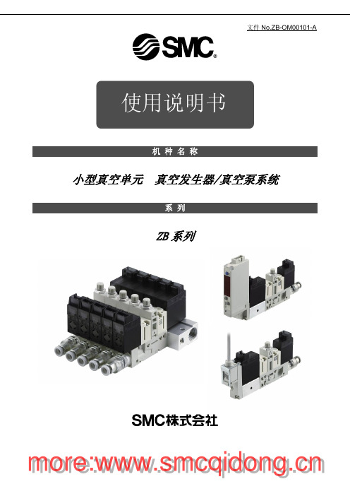
机 种 名 称小型真空单元 真空发生器/真空泵系统系 列ZB系列使用说明书目录安全注意事项 2 型号表示・型号体系 9 产品各部分名称 12 安装・设置 13 空气源 15 使用供给压力 16 配管 16 V通口Ass’y品的使用 17 关于电磁阀 21 构造图・零件构成 25 维护・保养 26 滤芯更换要领 28 吸音材更换要领 28 电磁阀(供给阀・破坏阀)更换要领 29 关于集装式产品 30 关于过滤罩 30 关于破坏流量调整针阀 31 关于真空发生器的排气 31 规格 32 回路图 35 重量 37 真空发生器的排气特性・流量特性 38 真空泵系统流量特性 39 关于流量特性表 40 关于压力传感器Ass’y品 40 关于真空用压力开关Ass’y品 41 故障一览表 42安全注意事项此处所示的注意事项是为了能安全正确的使用本产品,预先防止对您和他人造成危害或损失而定。
为了表示这些事项的危险程度,将注意事项分成「注意」「警告」和「危险」三个等级。
不论哪个等级,都是与安全相关的重要内容,除了必须遵守国际规格(ISO/IEC)、日本工业规格(JIS)※1)以及其他安全规则※2以外,这些内容也请务必遵守。
*1) ISO 4414: Pneumatic fluid power -- General rules relating to systems.ISO 4413: Hydraulic fluid power -- General rules relating to systems.IEC 60204-1: Safety of machinery --Electrical equipment of machines. (Part1: General requirements)ISO 10218-1992: Manipulating industrial robots -Safety.JIS B 8370: 空气压系统通则JIS B 8361: 油压系统通则JIS B 9960-1: 机械类的安全性-机械的电气装置((第1部:一般要求事项)JIS B 8433-1993: 键控工业机器人-安全性等*2) 劳动安全卫生法 等注意: 误使用时,有可能对人和物品造成损害。
SMC高真空角阀 直阀产品说明书-XMA XYA系列

Doc. no.XM-OMP0001-AHigh Vacuum Angle Valve / Straight ValveXMA/XYA SeriesThank you for purchasing SMC product.For appropriate operation of this product, please read this operation manual thoroughly to understand.Also, refer to the drawing, product information for structure and specification of this product, Confirm operating environment is within specifications.Keep this operation manual with care so that it can be usedat any time.Contents of this operation manual is subject to change without notice.Safety Instructions - - - - - - - - - - - - - - - - - - - - - - - - - - - - 2 1. Product Specific Precautions 1 - - - - - - - - - - - - - - - - - - - - - - - - - - - - 4(Precautions on Design, Selection, Mounting, Piping, Maintenance)2. Product Specific Precautions 2 - - - - - - - - - - - - - - - - - - - - - - - - - - - - 6(Maintenance parts)3. Specifications - - - - - - - - - - - - - - - - - - - - - - - - - - - - 74. Construction / Dimensions - - - - - - - - - - - - - - - - - - - - - - - - - - - - 85. Warranty period and guaranteed range - - - - - - - - - - - - - - - - - - - - - - - - - - - - 106.Parts replacement procedure - - - - - - - - - - - - - - - - - - - - - - - - - - - - 11Safety InstructionsThese safety instructions are intended to prevent hazardous situations and/or equipment damage. These instructions indicate the level of potential hazard with the labels of “Caution,” “Warning” or “Danger.”They are all important notes for safety and must be followed in addition to International Standards (ISO/IEC)*1), and other safety regulations.*1) ISO 4414: Pneumatic fluid power -- General rules relating to systems ISO 4413: Hydraulic fluid power -- General rules relating to systemsIEC 60204-1: Safety of machinery -- Electrical equipment of machines (Part 1: General requirements) ISO 10218-1992: Manipulating industrial robots -- SafetyCaution Caution indicates a hazard with a low level of risk which, if not avoided, could resultin minor or moderate injury.Warning Warning indicates a hazard with a medium level of risk which, if not avoided, could result in death or serious injury. DangerDanger indicates a hazard with a high level of risk which, if not avoided, will resultin death or serious injury .Safety InstructionsLimited warranty and Disclaimer/Compliance RequirementsThe product used is subject to the following “Limited warranty and Disclaimer” and “Compliance Requirements”.Read and accept them before using the product.Common Specific Precautions 1 Be sure to read before handling.●All models1. T he body material is SCS13, the bellows is SUS316L, and other metal seal material isSUS304. Standard seal material in the vacuum section is FKM that can be changed to the other materials (please refer “How to Order”). Use fluids those are compatible with using materials after confirming.2. S elect materials for the actuation pressure piping, and heat resistance for fittings that aresuitable for the applicable operating temperatures.●Models with auto switch1. T he switch section should be kept at the temperature no greater than 60 o C.●All models1. W hen controlling valve responsiveness, take note of the size and length of piping, as well asthe flow rate characteristics of the actuating solenoid valve.2. A ctuating press should be kept within the specified range. 0.4MPa to 0.5MPa is recommended.3. U se within the limits of the operating pressure range.●High temperature types1. I n the case of gases which cause a large amount of deposits, heat the valve body to preventdeposits in the valve.● All models1. I n high humidity environments, keep valves packed until the time of installation.2. I n case with switches, secure the lead wires so that they have sufficient slack, without anyunreasonable force applied to them.3. P erform piping so that excessive force is not applied to the flange sections. In case there isvibration of heavy objects or attachments, secure them so that torque is not applied directly to the flanges.4. V ibration resistance allows for normal operation of up to 30 m/s2(45 to 250Hz), butcontinuous vibration may cause a decline in durability.Arrange piping to avoid excessive vibration or impacts.● High temperature types; (Temperature specifications/H0)1. W hen a valve is to be heated, only the body section should be heated, excluding the bonnetsection.1. B efore mounting, clean the surface of the flange seal and the O-ring with ethanol, etc.2. T here is an indentation of 0.1 to 0.2mm in order to protect the flange seal surface, and itshould be handled so that the seal surface is not damaged in any way.If the fluid or reaction product (deposit) may cause the valve to become unsafe, the valve should be disassembled, cleaned and re-assembled by an operator who has sufficient knowledge and experience (e.g. a specialist).Caution1. When removing deposits from the a valve, take care not to damage any part of its parts.2. Replace the bonnet assembly and the O-ring when the end of its service life is approached. *For details regarding endurance cycles, please reference Section 5 of this Operation manual titled Period and scope of warranty . ( pages 10 )3. If damage is suspected prior to the end of the service life, perform early maintenance.4. SMC specified parts should be used for service. Refer to the Construction / Maintenance parts table.5. When removing the valve seal and external seal, take care not to damage the sealing surfaces. When installing the valve seal and external seal, be sure that the O-ring is not twisted. (Refer to Section 6 Parts Replacement Procedure (pages 11 to 13) for details.)Common Specific Precautions 2 Be sure to read before handlingOnly SMC specified parts should be used. Please refer to operation manual.The bonnet assembly should also be replaced when changing the seal material. Due to the different materials used, changing only the seal may prove inadequate.the magnet for auto switch is necessary, add “-M9//” a t the suffix of the part number. (Not available for hightemperature models)Note2) An auto switch for high temperature is available with a different part number.Note3) List the optional seal material symbol after the model number, except for the standard seal material (FKM: compound No. 1349-80).Note4) The bonnet assembly includes the valve seal.number, except for the standard seal material (FKM: compound no. 1349-80).Note2) Refer to the Construction on the page 9 for the construction numbers.Note3) Please contact SMC if you would like to change the material of the valve seal from ULTIC ARMOR to another material, or from another material to ULTIC ARMOR.Note1) Due to the different materials used, changing only the seal may prove inadequate.Note2) Barrel Perfluoro R is a registered trademark of MATSUMURA OIL Co.,Ltd.Kalrez R is a registered trademark of Dupont Co.,Ltd.Chemraz R is a registered trademark of Greene, Tweed & Co.,ULTIC ARMOR R is a registered trademark of NIPPON VALQUA INDUSTRIES, LTD.Note3) MITSUBISHI CABLE INDUSTRIES, LTD.3. SpecificationsNote1) XYA-16 is not available due to the interference of the flange shapeNote2) The conductance is “molecular flow” measured with an elbow pipe which has the same dimension with each flange.Note3) Air consumed by a reciprocating motion of a cylinder.Note4) Figures in ( ) indicates the weight of CF , conflate fittings.4-1. Construction))(保守部品))AAφGHBCCDφGHBEAφFd(K Flange )φFn (KF Flange )45°XMA Series /Angle ValveXYA Series / Straight ValveThe guaranteed period covers the period which finishes the earliest among 2 million operating cycles [with our durability test conditions], 18 months after shipping from us, and 12 months after starting the use of the product at your place or your c ustomer’s place.If the specification is not kept, or any non-conformance derived from mounting or replace of a device, an assembly, or an O-ring at your place occurs, the guarantee cannot be applied.Note)) The product durability is varied depending on the operating conditions (such as a use with large flow rate).If any failure occurs due to our fault during the guaranteed period, we will guarantee the non-conformance by delivering a substitute in the worst case. However, responsibility of any damage which is led by the product failure is not taken by us.Result of durability test (with the circuit shown on the right)Internal/ external leakage and operation were checked by opening and closing a valve in internally evacuated condition at ordinary temperature (room temperature).It was confirmed that this product satisfied the specification up to 2 million cycles.The test was performed with FKM, the standard sealing material.<Reference>The pumping direction is not limited, but if the pumping creates a flow stream, the durability of the product could be impaired.Therefore, the pumping direction shown on the right figure (bellows side pumping) is recommended. Also, the operating conditions should be checked beforehand because it affects the life.Vacuum pumpBellows side Valve sideChamberRecommended direction of exhaust6-1. PrecautionsBe sure to follow [1. Precautions 1] when disassembling the product for maintenance. Along with the precautions above, comply with the following precautions too.Warning∙If it is expected that product materials may get stuck to the product, ensure safety isassured before handling. It is recommended to wear gloves and a mask.∙Pay attention to the handling of components according to the procedure in the next itemonwards. Do not apply excessive force or impact. This will not only damage the productbut also decrease its performance and life expectancy.∙It is not possible to disassemble the bonnet assembly of this product. If the componentsand assembly are damaged, or damage is expected, exchange the bonnet assemblyitself.∙Do not disassemble the parts that are not explained in this operation manual. Theperformance and life may decrease. Also, it may cause danger.3Bolt124Bottomofdischarge gas.Mounting surface ofO ringBodyO ringO ringBodyBellows holder 1Pilot portBodyBonnet assembly234ValvesSizeX*A-251st Printing :PV 4-14-1, Sotokanda, Chiyoda-ku, Tokyo 101-0021 JAPANTel: + 81 3 5207 8249 Fax: +81 3 5298 5362URL Note: Specifications are subject to change without prior notice and any obligation on the part of the manufacturer.© 2012 SMC Corporation All Rights Reserved。
SMC-真空系统

27
SMCGZ Pneumatics Ltd.
真空系统
•从吸盘直径、真空度求不含安全率的理论吸吊力。 •然后,理论吸吊力除以安全率,求吸吊力。 •吸吊力=理论吸吊力×1/t
INTERNATIONAL TRAINING
10
SMCGZ Pneumatics Ltd.
真空泵系统
INTERNATIONAL TRAINING
11
SMCGZ Pneumatics Ltd.
切换阀:接通或断开真空压力源。 一般使用二位二通阀。
破坏阀:可控制吸盘对工件的吸着和脱离, 一般使用二位三通阀。
INTERNATIONAL TRAINING
28
SMCGZ Pneumatics Ltd.
真空系统
INTERNATIONAL TRAINING
29
SMCGZ Pneumatics Ltd.
真空系统
INTERNATIONAL TRAINING
30
SMCGZ Pneumatics Ltd.
真空系统
橡胶的材质和特性
INTERNATIONAL TRAINING
p 4wt 4196 4 0.0665Mpa D2n 502 6
W:负载的重力(N) t:安全系数;水平吸为4以上,垂直吸为8以上;
D:吸盘直径(mm); n:吸盘个数。
38
SMCGZ Pneumatics Ltd.
真空系统
真空系统案例选型
INTERNATIONAL TRAINING
INTERNATIONAL TRAINING
SMC ZQ A系列紧凑型真空单元说明书
Instruction ManualSpace Saving Vacuum UnitSeries ZQ□AThe intended use of the vacuum unit is to generate vacuum and controlthe operation of suction and release.These safety instructions are intended to prevent hazardous situations and/or equipment damage. These instructions indicate the level of potential hazard with the labels of “Caution,” “Warning” or “Danger.”They are all important notes for safety and must be followed in additionto International Standards (ISO/IEC) *1), and other safety regulations.*1) ISO 4414: Pneumatic fluid power - General rules relating to systems.ISO 4413: Hydraulic fluid power - General rules relating to systems.IEC 60204-1: Safety of machinery - Electrical equipment of machines. (Part 1: General requirements)ISO 10218-1: Manipulating industrial robots -Safety. etc.•Refer to product catalogue, Operation Manual and Handling Precautions for SMC Products for additional information.• Keep this manual in a safe place for future reference.Warning•Always ensure compliance with relevant safety laws and standards.•All work must be carried out in a safe manner by a qualified person in compliance with applicable national regulations. 2 SpecificationsNote *1) 10 to 150 Hz for 2 hours in each direction of X, Y and Z (De-energized, Initial valve).Note *2) 3 times in each direction of X, Y and Z (De-energized, Initial valve).measurement standards. They depend on atmospheric pressure (weather, altitude, etc.) and measurement method.Note *2) Must be 0.05MPa or more, lower than P Port pressure.Port Types: P: Air supply port, PD: Vacuum release port, PV: Common vacuum supply pressure port, PS: Common pilot pressure supply portNote *1) When needle is fully open.Note *2) Must be 0.05MPa or more, lower than PS Port pressure.3 Installation3.1 InstallationWarning•Do not install the product unless the safety instructions have been readand understood.•When mounting the product, tighten it with the recommendedtightening torque (0.54 to 0.66 N•m).•When mounting the manifold product, use the attached washers.•When installing the product, secure the space required formaintenance and inspection of the product•Do not drop, hit, or apply excessive impact to the product. 3.2 EnvironmentWarning•Do not use in an environment where corrosive gases, chemicals, salt water or steam are present.•Do not use in an explosive atmosphere.•Do not expose to direct sunlight. Use a suitable protective cover. •Do not install in a location subject to vibration or impact in excess of the product’s specifications.•Do not mount in a location exposed to radiant heat that would result in temperatures in excess of the product’s specifications•The suction filter used in this product is a simple one. If there is a lot of dust in the usage environment, please consider using a suction filter (ZFC series, etc.).•Do not use in place where static electricity build-up can occur.•Do not use in an environment where surges occur.3.3 Air SupplyCaution•Do not use air containing chemicals, synthetic oils containing organic solvents, salts, or corrosive gases.•Recommended quality of the supplied air be equivalent to the compressed air cleanliness grade "2: 6: 3" according to ISO8573-1: 2010.•Do not supply the pressure in excess of the product’s specificatio ns.3.4 PipingCaution•Before connecting piping make sure to clean up chips, cutting oil, dust, etc.•When piping pipe fittings to the pilot pressure exhaust (PE) port (M3) of the single specification, fix the parts where the port is installed, tighten by hand, and then use an appropriate tool to make about 1/4 turn. (Recommended tightening torque: 0.4 to 0.5 Nm)•When piping pipe fittings to the pilot pressure exhaust (P) port, etc. (M5) of the single specification, fix the parts where the port is installed, tighten by hand, and then use an appropriate tool to make about 1/6 to1/4 turn. (Recommended tightening torque: 1.0 to 1.5 Nm)•When piping the tube to the one-touch fitting, grasp the tube, slowly insert it into the one-touch fitting, and insert it all the way in. After inserting it all the way, pull the tube lightly and check that it does not come off.3.5 Wiring to the solenoid valve and pressure switchesRefer to the operation manual of solenoid valve (V100 series) and pressure switch (ZSE10 series). Manuals can be found by the links below:ZSE10: https:///manual/en-jp/?k=zse10V100: https:///manual/en-jp/?k=V1004 Settings4.1 Manual Override (With supply valve and release valve)Refer to the operation manual of the solenoid valve V100 series for the manual operation method.ORIGINAL INSTRUCTIONSManifoldSingle UnitManual of supply valveManual of release valve4.2 Release flow adjusting needleWhen the release valve is turned on, vacuum release air is let out.The release flow adjusting needle allows to control the vacuum break air flow rate.Loosen the lock nut and use a flat-blade screwdriver to adjust the release flow rate adjustment needle at the back of the lock nut.The breaking flow rate adjustment needle can be turned clockwise to reduce the release flow rate, and counterclockwise to increase the release flow rate.After adjusting the release flow rate adjustment needle, tighten the lock nut to fix the adjustment position.Refer to the catalogue for ‘How to Order’.Refer to the catalogue for outline dimensions.7.1 General MaintenanceCaution•Not following proper maintenance procedures could cause the product to malfunction and lead to equipment damage.• If handled improperly, compressed air can be dangerous.• Maintenanceofpneumatic systems should be performed only by qualified personnel.• Before performing maintenance, turn off the power supply and be sure to cut off the supplypressure. Confirm thattheair is released toatmosphere.• After installation and maintenance, apply operating pressure and power to the equipment and perform appropriate functional and leakage tests to make sure the equipment is installed correctly.• If any electrical connections are disturbed during maintenance, ensure they are reconnected correctly, and safety checks are carried out as required to ensure continued compliance with applicable national regulations.• Do not make any modification to the product.• Do not disassemble the product, unless required by installation or maintenance instructions • Implement the maintenance and check shown below to use the space saving vacuum unit safely and in an appropriate way for a long period of time.• Drain the air filter and mist separator regularly• Replace the sound absorbing material (silencer) built into the ejector regularly• Refer to the online operation manual for replacement parts. • Do not use benzene or thinner for cleaning7.2 Sound absorbing material replacement method • Single Unit− Loosen the assembly screws (2 pieces) of the silencer plate and remove the silencer plate (2 pieces) and the sound absorbing material.− Replace the silencer plate (2 sheets) and the sound absorbing material.− Assemble the silencer plate with the assembly screws (recommended tightening torque: 0.028 to 0.032 Nm).• Manifold− Loosen the two assembly screws of the silencer block and remove the silencer block.− Replace the sound absorbing material built into the silencer block. − Assemble the silencer block with the assembly screws (recommended tightening torque: 0.25 to 0.31 Nm).7.3 Filter element replacement method• Loosen the tension bolt and remove the filter case. • Replace the filter element built into the filter case.• Assemble the filter case with tension bolts (recommended tightening torque: 0.12 to 0.18 Nm).8.1 Limited warranty and Disclaimer/Compliance Requirements Refer to Handling Precautions for SMC Products.Caution• Exhaust from Space saving vacuum unit (ejector system)− For the silencer exhaust type, make sure that there is no obstruction around the exhaust port.− In the case of port exhaust type, exhaust resistance may be affected depending on the pipe diameter and length, so make sure that the back pressure is 1 kPa or less.− Do not block the exhaust port. • Ejector exhaust noiseWhen the vacuum ejector generates a vacuum, an intermittent noise (abnormal noise) may be generated from the exhaust section near the standard supply pressure where the vacuum pressure peaks, and the vacuum pressure may not be constant. There is no problem in use as long as the vacuum pressure range is sufficient for adsorption, but if you are concerned about the sound or affect the setting of the pressure switch, slightly change the supply pressure and reduce the range of the intermittent sound. Please avoid it.• About the release flow rate adjusting needle− Leakage cannot be reduced to zero when the needle is fully closed. − Since the release flow rate adjustment needle has a retaining mechanism, it will not rotate beyond the rotation stop position. If you try to turn the needle any further, it may be damaged.− When tightening the lock nut, tighten it by hand to about 15 to 30 degrees, and be careful not to damage it due to overtightening. • About solenoid valve and pressure switchFor the solenoid valve (V100 series) and pressure switch (ZSE10 series), refer to each instruction manual.9 Product disposalThis product should not be disposed of as municipal waste. Check your local regulations and guidelines to dispose this product correctly, in order to reduce the impact on human health and the environment.10 ContactsRefer to or www.smc.eu for your local distributor/importer.URL : https:// (Global) https:// www.smc.eu (Europe) SMC Corporation, 4-14-1, Sotokanda, Chiyoda-ku, Tokyo 101-0021, JapanSpecifications are subject to change without prior notice from the manufacturer. © 2021 SMC Corporation All Rights Reserved. Template DKP50047-F-085MTension bolt Filter case Filter element。
SMC-真空发生器
!"#$
ZL112 *采用3级扩压管,吸入流量可
**AC的场合,用整流器防止过电压的 发生,故无“S”。
真
空
压
力
吸入流量增加250%
吸入流量1
级
性
能
2级性
能
2级性能
ZL112
通口排气
ZL112P
带真空压力表
ZL112-G
带真空用接头
ZL112-GN
带数字式真空压力开关
ZL112-E
2-ø5.4
带供给阀、破坏阀
ZL112-K1□L□□-E25(L)-M带供给阀
!
通口排气
ZL212P
带真空压力表
ZL212-G
带真空接头
ZL212-GN
带真空用数字式压力开关
ZL212-E
标准型
带真空压力表
带真空用数字式压力开关
带真空接头
通口排气
*采用上下重叠两个3级扩压管,
节省流量和吸入流量都是
ZL112的2倍
*可带真空压力表或压力开关
*可内置消声器
*可两个方向安装(底、侧)
型号表示方法
*无记号、真空用接头(GN)、带真空压
(G)的场合无此项。
外形尺寸图(毫米)
!"#$
ZL212。
SMC 真空系统
SMC 真空系统一、引言本文档旨在介绍和说明使用和维护SMC真空系统的相关信息。
SMC真空系统是一套先进的真空设备,广泛应用于工业生产和实验研究领域。
本文档将按照以下章节对SMC真空系统进行详细描述。
二、系统概述本章节介绍SMC真空系统的总体结构和主要组成部分。
包括真空泵、真空压力控制器、真空传感器和其他相关设备。
详细描述每个组件的功能和特点。
三、安装与调试本章节详细说明SMC真空系统的安装和调试流程。
包括安装位置的选择、管道连接、电源接线等。
同时提供调试方法和常见故障排除步骤。
四、操作指南本章节提供SMC真空系统的操作指南。
包括系统启动和关闭、真空泵开启和停止、真空度调节、压力控制器的设置等操作步骤。
同时针对不同实际应用场景给出操作注意事项和优化建议。
五、维护与保养本章节介绍SMC真空系统的日常维护和保养要点。
包括定期清洁、润滑和更换部件、维护记录的保存等。
同时提供常见故障的排查和解决方法。
六、安全注意事项本章节列出使用SMC真空系统时需要注意的安全事项。
包括高压风险、电气安全、防止污染等方面的指导。
同时提供应急处理措施和紧急停机程序。
七、附件1、SMC真空系统安装图纸2、SMC真空系统维护记录表格3、SMC真空系统产品说明书八、法律名词及注释1、涉及的法律名词:a:真空设备:指用来创造和维持一定低压环境的设备,以进行各种实验和工业生产过程。
b:压力控制器:指用来控制和调节真空系统压力的设备,以满足各种工艺需求。
c:安全事项:指使用真空系统时需要遵守和注意的各种安全原则和规定。
2、注释:a: SMC真空系统:SMC公司生产的一套完整的真空设备解决方案。
b:维护记录表格:用于记录每次维护和保养工作的表格,以便开展合理的设备维护管理。
SMC气动第三册(真空元件)
注意
1 方向控制阀,速度控制阀等相关元件应参见各自样本的注意 事项。
维护
警告
1 要定期对真空过滤器和消声器进行清洗。
过滤器及消声器的孔眼被堵, 真空发生器的性能便降低。 在粉尘多的 场合,应使用处理流量大的真空过滤器。
前附5-1
!"
!
ZH
型号 · 规格 · 最大吸入流量/空气消耗量
型号 ZH05B□ ZH07B□ ZH10B□ ZH13B□ ZH05D□ ZH07D□ ZH10D□ ZH13D□ ZH15D□ ZH18D□ ZH20D□ 喷嘴 直径 ømm 0.5 0.7 1.0 1.3 0.5 0.7 1.0 1.3 1.5 1.8 2.0 主体形式 *最高真空度 kPa S型 L型 最大吸入流量 /min(ANR) S型 L型 5 8 12 20 24 34 40 70 5 8 12 20 24 34 40 70 55 75 65 110 85 135 空气消耗量 /min(ANR) S型 · L型 13 23 46 78 13 23 46 78 95 150 185
catc0505acatc0506acatc0610acatc0609ccatcep2acate804abestpneumatics2004vol13cate813bcate813b01e492cate801acate806bcate815acate831acate832abestpneumatics2004vol13bestpneumatics2004vol13bestpneumatics2004vol13bestpneumatics2004vol13bestpneumatics2004vol13bestpneumatics2004vol13bestpneumatics2004vol13bestpneumatics2004vol13bestpneumatics2004vol13bestpneumatics2004vol13bestpneumatics2004vol13cate817acate802bbestpneumatics2004vol16cate808acates6016acates6015dcate827acate810acate803bcate809acatc0607ccatc0703bcates10042ccates10043acats10042ccats10043acatsp2ccats1405a501503504506507509511515522523534536537538539542544546547548551553554557559560561563564565568570572573574真空发生器直管型真空发生器多级真空发生器多级真空发生器带电子式延时器的真空发生器薄型真空发生器真空发生器组件真空发生器组件小型真空发生器组件大型真空发生器组件真空发生器与电磁阀的组合真空过滤器小型真空过滤器真空吸盘250垂直真空口接管吸盘不带缓冲带缓冲水平真空口接管吸盘不带缓冲带缓冲水平真空口倒钩式接管吸盘不带缓冲带缓冲特殊真空吸盘大型真空吸盘40125大型垂直真空口接管吸盘不带缓冲带缓冲大型水平真空口接管吸盘不带缓冲带缓冲大型风琴形真空吸盘40125大型垂直真空口接管风琴形吸盘不带缓冲带缓冲大型水平真空口接管风琴形吸盘不带缓冲带缓冲带单向阀的真空吸盘微型电子式真空压力开关真空压力开关高精度数字式真空压力开关吸着确认开关真空用气缸真空调压阀电气比例阀真空用真空用分水过滤器高真空阀cats1006cc
- 1、下载文档前请自行甄别文档内容的完整性,平台不提供额外的编辑、内容补充、找答案等附加服务。
- 2、"仅部分预览"的文档,不可在线预览部分如存在完整性等问题,可反馈申请退款(可完整预览的文档不适用该条件!)。
- 3、如文档侵犯您的权益,请联系客服反馈,我们会尽快为您处理(人工客服工作时间:9:00-18:30)。
INTERNATIONAL TRAINING
23
SMCGZ Pneumatics Ltd.
真空系统选型
INTERNATIONAL TRAINING
24
SMCGZ Pneumatics Ltd.
真空系统选型
INTERNATIONAL TRAINING
25
SMCGZ Pneumatics Ltd.
真空系统选型
•还要考虑到吸盘的个数及配置情况给予裕量。 •求理论吸吊力的方法:吸盘的吸吊,可由计算式或表①理论吸吊力表求得。
27
SMCGZ Pneumatics Ltd.
12
SMCGZ Pneumatics Ltd.
INTERNATIONAL TRAINING
13
SMCGZ Pneumatics Ltd.
真空发生器系统----组件
INTERNATIONAL TRAINING
14
SMCGZ Pneumatics Ltd.
真空发生器系统----组件
供给阀:供给真空发生器压缩空气的阀。 破坏阀:破坏吸盘内的真空状态,使工件脱离吸盘。
17
SMCGZ Pneumatics Ltd.
真空系统
真空系统组成
真空压力开关
INTERNATIONAL TRAINING
确保安全吸住工件的真空压力,输出电信号给真空控制系统。
ZSP1
ZSE2
ZSE3
PSE1100
ZSE30A
18
SMCGZ Pneumatics Ltd.
真空系统
真空系统组成
INTERNATIONAL TRAINING
真空系统
真空发生器工作原理
INTERNATIONAL TRAINING
8
SMCGZ Pneumatics Ltd.
真空系统
INTERNATIONAL TRAINING
•不仅有单段式真空发生器,还有由多个真空发生器组成的多段式真空发生器。 •多段式真空发生器,可以增加吸入流量,比单段式真空发生器的吸入流量大。
INTERNATIONAL TRAINING
26
SMCGZ Pneumatics Ltd.
真空系统
INTERNATIONAL TRAINING
•根据算出的吸盘的吸吊力求吸盘的直径。 •有时,计算值作为参考值,还要进行必要的吸着试验来确认。 •吸吊力的计算要根据工件的重量及移动时(上升、停止、回转等)的加速度 产生的惯性力,给予充分的裕量。
一般使用二位二通阀。
INTERNATIONAL TRAINING
15
SMCGZ Pneumatics Ltd.
INTERNATIONAL TRAINING
16
SMCGZ Pneumatics Ltd.
真空系统
真空系统组成
真空调压阀
INTERNATIONAL TRAINING
调节真空系统压力并保持其稳定,通用于真空泵系统中。
INTERNATIONAL TRAINING
单向阀 ✓ 当供给阀停止供气时,保持吸盘内的真空压力。
✓ 安全考虑,可延缓被吸吊工件脱落的时间。应选用流通能力大、开启压力 低(0.01Mpa)的单向阀,SMC公司有AK系列的单向阀可选用。
节流阀 用于控制真空破坏的快慢,节流阀出口压力不得高于0.5Mpa,可使用AS
活塞式
螺杆式
离心式
6
SMCGZ Pneumatics Ltd.
真空系统
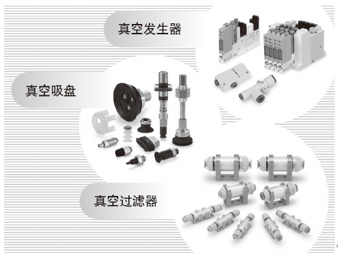
产生真空的设备
INTERNATIONAL TRAINING
真空发生器
利用压缩空气的流动而形成一定真空度的气动元件.最大 真空可达-88kpa.
盒式真空发生器ZH系列
管式真空发生器ZU系列
7
SMCGZ Pneumatics Ltd.
1
SMCGZ Pneumatics Ltd.
2
SMCGZ Pneumatics Ltd.
真空系统
什么是真空?
INTERNATIONAL TRAINING
3
SMCGZ Pneumatics Ltd.
真空系统
什么是真空?
真空吸附和气缸的动作原理基本上是一样的, 即为利用压力差来实现动作。
INTERNATIONAL TRAINING
复杂
大
重
有可动件,寿命较长
较大
高
不便
需要
困难
慢
有脉动,需设真空罐
真空发生器
可达88kPa 不大
}不能同时获得大值
简单Байду номын сангаас
很小
很轻
无可动件,寿命长
较大
低
方便
不需要
容易
快
无脉冲,不需真空罐
适合连续.大流量工作,不宜频繁启停,适合集 需供应压缩空气,宜从事流量不大的间歇工作,
中使用
适合分散使用.改变材质,可实现耐热.耐腐蚀.
9
SMCGZ Pneumatics Ltd.
真空系统
INTERNATIONAL TRAINING
项目 最大真空度 吸入流量
结构 体积 重量 寿命 消耗功率 价格 安装 维护 与配套件复合化 真空的产生及解除 真空压力脉冲
应用场合
两种真空发生装置特点
真空泵
可达101.3kPa 可很大
}能同时获得大值
4
SMCGZ Pneumatics Ltd.
真空系统
真空的应用
集成电路的接合
拾取及传送
INTERNATIONAL TRAINING
电路元件安装
传送印刷纸张
5
SMCGZ Pneumatics Ltd.
真空系统
产生真空的设备
INTERNATIONAL TRAINING
真空泵
吸入口形成负压,排气口直接通大气,两端压力比很 大的抽除气体的机械;最大真空可达-101.33kpa.
系列弯头型带快换接头的速度控制阀。
20
SMCGZ Pneumatics Ltd.
真空系统选型
INTERNATIONAL TRAINING
21
SMCGZ Pneumatics Ltd.
真空系统选型
INTERNATIONAL TRAINING
22
SMCGZ Pneumatics Ltd.
真空系统选型
真空过滤器
将由真空吸盘从大气中吸的的污染物(主要为尘埃)进行隔离排除, 确保真空发生器不会堵塞,正常工作。
不能用AF系列过滤器取代ZF系列过滤器(负压段)。当过滤器两 端压降大于0.02Mpa时,滤芯应卸下清洗或更换。
19
SMCGZ Pneumatics Ltd.
真空系统
真空系统组成
真空系统中常应用到节流阀和单向阀
10
SMCGZ Pneumatics Ltd.
真空泵系统
INTERNATIONAL TRAINING
11
SMCGZ Pneumatics Ltd.
切换阀:接通或断开真空压力源。 一般使用二位二通阀。
破坏阀:可控制吸盘对工件的吸着和脱离, 一般使用二位三通阀。
INTERNATIONAL TRAINING