Microphone Array and Beamforming - Forward麦克风阵列波束形成了
ADMP504ACEZ-RL7 超低噪声麦克风数据手册说明书

ADMP504ACEZ-RL7Ultralow Noise Microphone with Bottom Port and Analog OutputData SheetADMP504Rev. AInformation furnished by Analog Devices is believed to be accurate and reliable. However , no responsibility is assumed by Analog Devices for its use, nor for any infringements of patents or other rights of third parties that may result from its use. Specifications subject to change without notice. No license is granted by implication or otherwise under any patent or patent rights of Analog Devices. T rademarks and registered trademarks are the property of their respective owners.O ne Technology Way, P.O. Box 9106, Norwood, MA 02062-9106, U.S.A. Tel: 781.329.4700 Fax: 781.461.3113 ©2011–2012 Analog Devices, Inc. All rights reserved.FEATURESTiny, 3.35 mm × 2.50 mm × 0.88 mm surface-mount package Omnidirectional response Very high SNR of 65 dBA Sensitivity of −38 dBVExtended frequency response from 100 Hz to 20 kHz Low current consumption: 180 µA Single-ended analog output 120 dB maximum SPL High PSR of 70 dBVCompatible with Sn/Pb and Pb-free solder processes RoHS/WEEE compliantAPPLICATIONSSmartphones and feature phones Tablet computersTeleconferencing systems Digital still and video cameras Bluetooth headsets Notebook PCsSecurity and surveillanceFUNCTIONAL BLOCK DIAGRAM10140-001DDOUTPUTFigure 1.10140-011Figure 2. Isometric Views of ADMP504 Microphone PackageGENERAL DESCRIPTIONThe ADMP5041 is a high performance, very low noise, low power, analog output, bottom-ported omnidirectional MEMS microphone. The ADMP504 consists of a MEMS microphone element, an impedance converter and an output amplifier. The ADMP504 sensitivity specification makes it an excellent choice for both near field and far field applications. The ADMP504 is function- and pin-compatible with the ADMP404 microphone, providing an easy upgrade path.The ADMP504 has very high SNR and extended wideband frequency response, resulting in natural sound with highintelligibility. Low current consumption enables long battery life for portable applications. The ADMP504 complies with the TIA-920 Telecommunications Telephone Terminal Equipment Transmission Requirements for Wideband Digital Wireline Telephones standard.The ADMP504 is available in an ultraminiature 3.35 mm × 2.5 mm × 0.88 mm surface-mount package. It is reflow solder compatible with no sensitivity degradation. The ADMP504 is halide free.1Protected by U.S. Patents 7,449,356; 7,825,484; 7,885,423; 7,961,897. Other patents are pending.OBS OEADMP504Data SheetRev. A | Page 2 of 12TABLE OF CONTENTSFeatures .............................................................................................. 1 Applications ....................................................................................... 1 Functional Block Diagram .............................................................. 1 General Description ......................................................................... 1 Revision History ............................................................................... 2 Specifications ..................................................................................... 3 Absolute Maximum Ratings ............................................................ 4 ESD Caution .................................................................................. 4 Pin Configuration and Function Descriptions ............................. 5 Typical Performance Characteristics ............................................. 6 Applications Information ................................................................ 7 Supporting Documents ................................................................7 Handling Instructions .......................................................................8 Pick-and-Place Equipment ..........................................................8 Reflow Solder .................................................................................8 Board Wash ....................................................................................8 PCB Land Pattern Layout .................................................................9 Reliability Specifications ................................................................ 10 Outline Dimensions ....................................................................... 11 Ordering Guide .. (11)REVISION HISTORY6/12—Rev. 0 to Rev. AChanges to Figure 2 .......................................................................... 1 Changes to General Description Section ...................................... 1 Change to Power Supply Rejection Parameter, Table 1 ............... 3 Changes to Supporting Documents Section ................................. 7 Changes to Reflow Solder Section .. (8)10/11—Revision 0: Initial VersionOBS OL E T EData SheetADMP504Rev. A | Page 3 of 12SPECIFICATIONST A = 25°C, V DD = 1.8 V , unless otherwise noted. All minimum and maximum specifications are guaranteed. Typical specifications are not guaranteed. Table 1.Parameter Symbol Test Conditions/Comments Min Typ Max Unit PERFORMANCEDirectionalityOmni Sensitivity1 kHz, 94 dB SPL−41 −38 −35 dBV Signal-to-Noise Ratio SNR 20 Hz to 20 kHz, A-weighted 65 dBA Equivalent Input Noise EIN 20 Hz to 20 kHz, A-weighted29 dBA SPL Dynamic RangeDerived from EIN and maximum acoustic input 91 dB Frequency Response 1 Low frequency −3 dB point 100 HzHigh frequency −3 dB point >20 kHz Total Harmonic Distortion THD 104 dB SPL3 % Power Supply Rejection PSR217 Hz, 100 mV p-p square wave superimposed on V DD = 1.8 V −70 dBV Maximum Acoustic Input Peak, 10% THD 120 dB SPL POWER SUPPLY Supply Voltage V DD1.6 3.3 V Supply Current I S V DD = 1.8 V 180 200 µAV DD = 3.3 V 200 225 µA OUTPUT CHARACTERISTICS Output Impedance Z OUT 200 Ω Output DC Offset 0.8 V Output Current Limit90 µA Maximum Output Voltage 120 dB SPL input, peak0.25 V Noise Floor20 Hz to 20 kHz, A-weighted, rms−103dBV1See Figure 5 and Figure 7.OBS OL E T EADMP504Data SheetRev. A | Page 4 of 12ABSOLUTE MAXIMUM RATINGSTable 2.Parameter RatingSupply Voltage−0.3 V to +3.6 V Sound Pressure Level (SPL) 160 dB Mechanical Shock 10,000 gVibrationPer MIL-STD-883 Method 2007, Test Condition B Temperature Range−40°C to +85°CStresses above those listed under Absolute Maximum Ratings may cause permanent damage to the device. This is a stress rating only; functional operation of the device at these or any other conditions above those indicated in the operationalsection of this specification is not implied. Exposure to absolute maximum rating conditions for extended periods may affect device reliability.ESD CAUTION101T E M P E R A T U R ETIMET TFigure 3. Recommended Soldering Profile LimitsTable 3. Recommended Soldering Profile LimitsProfile FeatureSn63/Pb37Pb-FreeAverage Ramp Rate (T L to T P ) 1.25°C/sec maximum 1.25°C/sec maximum PreheatMinimum Temperature (T SMIN ) 100°C 150°C Maximum Temperature (T SMAX ) 150°C200°CTime (T SMIN to T SMAX ), t S 60 sec to 75 sec 60 sec to 75 sec Ramp-Up Rate (T SMAX to T L )1.25°C/sec1.25°C/sec Time Maintained Above Liquidous (t L ) 45 sec to 75 sec ~50 sec Liquidous Temperature (T L ) 183°C217°CPeak Temperature (T P )215°C + 3°C/−3°C 260°C + 0°C/−5°C Time Within 5°C of Actual Peak Temperature (t P ) 20 sec to 30 sec 20 sec to 30 sec Ramp-Down Rate3°C/sec maximum 3°C/sec maximum Time 25°C to Peak Temperature5 minutes maximum 5 minutes maximumOBS T EData SheetADMP504Rev. A | Page 5 of 12PIN CONFIGURATION AND FUNCTION DESCRIPTIONSGNDOUTPUTTOP VIEW(TERMINAL SIDE DOWN)Not to ScaleADMP5041V DD3210140-003Figure 4. Pin ConfigurationTable 4. Pin Function DescriptionsPin No. Mnemonic Description1 OUTPUT Analog Output Signal2 GND Ground3V DDPower SupplyOBS OL E T EADMP504Data SheetRev. A | Page 6 of 12TYPICAL PERFORMANCE CHARACTERISTICS–10–8–6–4–2024681010010k 1kFREQUENCY (Hz)S E N S I T I V I T Y(d B )10140-004Figure 5. Frequency Response Mask0–8010010kFREQUENCY (Hz)P S R (d B )1k–10–20–30–40–50–60–7010140-005Figure 6. Typical Power Supply Rejection vs. Frequency10–2020FREQUENCY (Hz)S E N S I T I V I T Y (d B )1001k 10k5–10–5–1510140-006Figure 7. Typical Frequency Response (Measured)OBS OL E T EData SheetADMP504Rev. A | Page 7 of 12APPLICATIONS INFORMATIONThe ADMP504 output can be connected to a dedicated codecmicrophone input (see Figure 8) or to a high input impedance gain stage (see Figure 9). A 0.1 μF ceramic capacitor placed close to the ADMP504 supply pin is used for testing and is recom-mended to adequately decouple the microphone from noise on the power supply. A dc-blocking capacitor is required at the output of the microphone. This capacitor creates a high-pass filter with a corner frequency atf C = 1/(2π × C × R )where R is the codec’s input impedance.A minimum value of 2.2 μF is recommended in Figure 8 because the input impedance of the ADAU1361/ADAU1761 can be as low as 2 kΩ at its highest PGA gain setting, which would result in a high-pass filter corner frequency at about 37 Hz. Figure 9 shows the ADMP504 connected to an ADA4897-1 op amp configured as a noninverting preamplifier.10140-007Figure 8. ADMP504 Connected to the Analog Devices ADAU1761or ADAU1361 Codec10140-008GAIN =(R1+R2)/R1OUTFigure 9. ADMP504 Connected to the ADA4897-1 Op AmpSUPPORTING DOCUMENTSEvaluation Board User GuideUG-325, EVAL-ADMP504Z-FLEX: Bottom-Ported Analog Output MEMS Microphone Evaluation BoardCircuit Note CN-0207, High Performance Analog MEMS Microphone’s Simple Interface to SigmaDSP Audio CodecApplication NotesAN-1003, Recommendations for Mounting and Connecting Analog Devices, Inc., Bottom-Ported MEMS Microphones AN-1068, Reflow Soldering of the MEMS Microphone AN-1112, Microphone Specifications ExplainedAN-1124, Recommendations for Sealing Analog Devices, Inc., Bottom-Port MEMS Microphones from Dust and Liquid IngressAN-1140, Microphone Array BeamformingOBS L E T EADMP504Data SheetRev. A | Page 8 of 12HANDLING INSTRUCTIONSPICK-AND-PLACE EQUIPMENTThe MEMS microphone can be handled using standard pick-and-place and chip shooting equipment. Take care to avoid damage to the MEMS microphone structure as follows: •Use a standard pickup tool to handle the microphone. Because the microphone hole is on the bottom of the package, the pickup tool can make contact with any part of the lid surface.•Use care during pick-and-place to ensure that no high shock events above 10 k g are experienced because this may cause damage to the microphone.•Do not pick up the microphone with a vacuum tool that makes contact with the bottom side of the microphone. Do not pull air out or blow air into the microphone port. • Do not use excessive force to place the microphone on the PCB.REFLOW SOLDERFor best results, the soldering profile should be in accordance with the recommendations of the manufacturer of the solder paste used to attach the MEMS microphone to the PCB. It is recommended that the solder reflow profile not exceed the limit conditions specified in Figure 3 and Table 3.BOARD WASHWhen washing the PCB, ensure that water does not make contact with the microphone port. Blow-off procedures and ultrasonic cleaning must not be used.OBS OL E T EData SheetADMP504Rev. A | Page 9 of 12PCB LAND PATTERN LAYOUTThe recommended PCB land pattern for the ADMP504 should be laid out to a 1:1 ratio to the solder pads on the microphone package, as shown in Figure 10. Take care to avoid applying solder paste to the sound hole in the PCB. A suggested solder paste stencil pattern layout is shown in Figure 11. The diameter of the sound hole in the PCB should be larger than the diameter of the sound port of the microphone. A minimum diameter of 0.5 mm is recommended.10140-009Figure 10. PCB Land Pattern Layout10140-0101.55/1.05 DIA.Figure 11. Suggested Solder Paste Stencil Pattern LayoutOADMP504Data SheetRev. A | Page 10 of 12RELIABILITY SPECIFICATIONSThe microphone sensitivity after stress must deviate by no more than 3 dB from the initial value. Table 5.Stress TestDescriptionLow Temperature Operating Life −40°C, 1000 hrs, powered High Temperature Operating Life +125°C, 1000 hrs, poweredTemperature Humidity Bias (THB) +85°C/+85% relative humidity (RH), 1000 hrs, powered Temperature Cycle−40°C/+125°C, one cycle per hour, 1000 cycles High Temperature Storage +150°C, 1000 hrs Low Temperature Storage −40°C, 1000 hrs Component CDM ESD All pins, 0.5 kV Component HBM ESD All pins, 1.5 kV Component MM ESDAll pins, 0.2 kVOBS OL E T EData SheetADMP504Rev. A | Page 11 of 12OUTLINE DIMENSIONS06-16-2010-AREFREFDIA.DIA.THRU HOLE (SOUND PORT)Figure 12. 3-Terminal Chip Array Small Outline No Lead Cavity [LGA_CAV]3.35 mm × 2.50 mm Body(CE-3-2)Dimensions shown in millimetersORDERING GUIDEModel 1Temperature Range Package DescriptionPackage Option 2 Ordering Quantity ADMP504ACEZ-RL −40°C to +85°C 3-Terminal LGA_CAV, 13” Tape and Reel CE-3-2 10,000 ADMP504ACEZ-RL7 −40°C to +85°C 3-Terminal LGA_CAV, 7” Tape and Reel CE-3-2 1,000 EVAL-ADMP504Z-FLEXFlex Evaluation Board1 Z = RoHS Compliant Part.2This package option is halide free.OBS OL E TADMP504Data SheetRev. A | Page 12 of 12NOTES©2011–2012 Analog Devices, Inc. All rights reserved. Trademarks and registered trademarks are the property of their respective owners.D10140-0-6/12(A)OBS OL ET EADMP504ACEZ-RL7。
声场重构中消除鬼影和提高重构精度的方法

文章编号:1006-1355(2013)04-0200-07声场重构中消除鬼影和提高重构精度的方法付强1,2,黎敏1,2,樊悦1,2,魏龙1,2(1.北京科技大学新型飞行器技术研究中心,北京100083;2.北京科技大学机械工程学院,北京100083)摘要:在利用波束形成算法进行声场重构时,容易出现鬼影现象,给重构声场的准确辨识带来极大困难。
在对波束形成算法进行理论推导后,获得麦克风阵列的结构参数与鬼影产生的关系,进而获得消除鬼影的方法;并在此基础上,优化麦克风阵列的布局形式,设计阵列的最大孔径比,可以有效提高重构精度。
通过纯音实验和窄带噪声实验,验证了消除鬼影和提高声场重构精度方法的有效性。
关键词:声学;声场重构;波束形成;鬼影;重构精度中图分类号:TB132;TB534+.3文献标识码:A DOI编码:10.3969/j.issn.1006-1335.2013.04.042 Method of Eliminating Ghost Images and Improving Reconstruction Precision in Acoustic-fields ReconstructionFU Qiang,LI Min,FAN Yue,WEI Long(1.Reasearch Center for Aerospace Vehicles Technology,University of Science and Technology Beijing,Beijing100083,China;2.School of Mechanical Engineering,University of Science and Technology Beijing,Beijing100083,China)Abstract:The ghost images can occur easily in the reconstruction of acoustic fields with the use of beamforming algorithm,which leads to a terrible difficulty for accurate identification of the reconstructed acoustic fields.After detailed deduction of the beamforming algorithm,the relation between the shape parameters of microphone array and the ghost-images occurrence was obtained,and the method for eliminating the ghost images were attained.It was found that after the elimination of ghost images,the reconstruction precision would be improved if the value of D/λwas increased by means of optimization design of the array’s configuration.Finally,the effectiveness and feasibility of this method was verified by some experiments of acoustic-field reconstruction of some pure sound and narrow-band noises.Key words:acoustics;reconstruction of acoustic fields;beamforming;ghost image;reconstruction precision收稿日期:2012-08-29;修改日期:2012-12-10项目基金:国家重大科学仪器设备开发专项:(2011YQ14014507);中央高校基本科研业务费专项资金:(FRF-AS-12-003);中央高校基本科研业务费专项资金:(FRF-MP-12-002A)作者简介:付强(1983-),男,山东日照人,博士,目前从事高温声场测量与重构、材料与构件声疲劳研究。
MicrophoneArrayF...

Low scalability due to dimensions increasing
September 15, 2005
9
Estimation and suppression
Signal variance
Signal and noise variances
100
λY ( f
| ∆)
E
⎡ ⎢⎣
Y
(
f
|
∆
)
2
⎤ ⎥⎦
λD ( f
| ∆)
E
⎡ ⎢⎣
D( f
|
∆
)
2
⎤ ⎥⎦
a priory and a posteriori SNR
IWAENC 2005, Eindhoven
14
-1
Arrival (IDOA) space:
-2
∆( f ) [δ1( f ),δ2 ( f ),…,δM −1( f )]
-3 -3
-2
-1
0
1
2
3
D12
where δ j−1( f ) = arg( X1( f )) − arg( X j ( f ))
September 15, 2005
IWAENC 2005, Eindhoven
September 15, 2005
Hk =
ξk 1+ ξk
⎛ ⎜ ⎝
1
+ν γk
k
⎞ ⎟ ⎠
数字助听器中广义旁瓣消除器的仿真研究

数字助听器中广义旁瓣消除器的仿真研究雍雅琴;沙洪;李鹏【摘要】Objective To deal with the digital hearing aids in competing talker situations using speech enhancement algorithm.Methods For adaptive beam forming algorithm using microphone array,the frequency-domain adaptive beamforming algorithm based on robustness time-domain GSC structure was studied.Results The simulation was designed for the frequency-domain adaptive beamforming algorithm,and the computational complexity and convergence rate were compared between the frequency domain GSC and the time domain GSC.Conclusion The simulation results show that the frequency-domain GSC adaptive bearmforming algorithm has a higher calculation speed and convergence rate,and thus has more research significance when compared with time-domain GSC.[Chinese Medical Equipment Journal,2013,34(5):13-15,81]%目的:研究数字助听器中竞争语音情形下的语音增强算法.方法:针对语音增强算法中的麦克风阵列自适应波束形成算法,简要回顾了广义旁瓣消除器(GSC)结构的鲁棒性时域自适应波束形成算法,研究了频域GSC结构的自适应波束形成算法.结果:设计仿真实验,对比时、频域GSC的计算复杂度和收敛速度.结论:仿真结果显示,频域GSC 结构的自适应波束形成算法与时域GSC对比,具有计算速度快、收敛性能好的优点.【期刊名称】《医疗卫生装备》【年(卷),期】2013(034)005【总页数】4页(P13-15,81)【关键词】自适应波束形成;频域广义旁瓣消除器;复杂度;收敛速度【作者】雍雅琴;沙洪;李鹏【作者单位】中国医学科学院北京协和医学院生物医学工程研究所,天津300192;中国医学科学院北京协和医学院生物医学工程研究所,天津300192;杭州爱听科技有限公司,杭州310023【正文语种】中文【中图分类】R318.6;TH785.10 引言语音增强是数字助听器算法的重要组成部分[1],研究其有重大意义。
Sennheiser TeamConnect Ceiling 2 产品说明说明书

FEATURES• Ceiling array microphone with patented automatic speaker position detection and dynamic beamforming for best speech intelligibility• Analog and digital (Dante™) audio outputs for easy connectivity to video and audio conference systems • Configuration and monitoring via Sennheiser´s unique Control Cockpit software• Open API for media and camera control applications • Several installation options via suspension kit, flush-mount or surface bracket TeamConnect Ceiling 2 offers superior audio quality for voice and video conferences. Thanks to Sennheiser’s pa-tented adaptive beamforming technology it automatically follows the active speaker’s voice, letting people speak naturally – whether they are sitting, standing or walking around the room. TeamConnect Ceiling 2 offers great versatility and interoperability with support for Dante™ networks and Power over Ethernet. It is compatible with Sennheiser’s Control Cockpit software for efficient remote management, and offers remote configuration and monito-ring via an open media control protocol (API), allowing for easy integration into media systems and camera controlapplications.SPECIFICATIONSDimensions (L x B x H)590 x 590 x 43 mm(23.2" x 23.2" x 1.7")Weight 6 kg (13.2 lbs)Audio Output 1 x 3-pin terminals (fits Phoenixcontact MCVW 1.5-3-ST-3.81)2 x Digital Dante Network Audio(RJ45)Ethernet / Control 1 x RJ45 Ethernet Port for PoEpower supply and data / controlcommunicationSupply voltage44 – 57 V DC (via PoE) Temperature Operation: 0 – 40 °C(32 - 104 °F)Storage: -10 – 60 °C(14 - 140 °F)Relative humidity20 – 95 %,non condensingMicrophone type pre-polarized condenser micro-phoneSensitivity-1 dBV/Pa (930 mV/Pa)Number of KE 10-237 microphone capsules 28Pick-up pattern Beam patternMax. sound pressurelevel119 dB SPLDynamic range99 dB(A)DELIVERY INCLUDES• SL Ceiling Mic 2• Mounting instructions• Drilling templateACCESSORIESSL CM FB Mounting bracket Art.-No. 506846SL CM EB US Extension brackets Art.-No. 508528SL CM EB 625Extension brackets Art.-No. 508290SL CM SK Suspension kit Art.-No. 508291DIMENSIONS SL Ceiling Mic 2CONNECTIONS AND OPERATING ELEMENTSPrimaryResetSecondaryAnalog Out DanteEthernetPoE/CtrlDante Dante™ interface with two RJ 45 sockets Primary and Secondary Reset Factory reset switchAnalog Out 3-pin terminal for analog audio out EthernetRJ 45 socket for network controlDIMENSIONSSL CM FB - Mounting bracket (Surface)2Sennheiser electronic GmbH & Co. KG · Am Labor 1 · 30900 Wedemark · Germany · ARCHITECT‘S SPECIFICATIONThe ceiling mounted microphone shall be designed for fixed installation in medium to large conference rooms where table microphones are not desirable or possible. The microphone shall fit within the space of a standard 600 mm (2 ft.) ceiling panel and shall be mountable either onto or flush with the ceiling itself. Several mounting accessories shall be available, including a ceiling suspension kit, a ceiling fixation bracket as well as mounting brackets for US size ceiling panels and for 625 mm ceiling panels.The microphone shall consist of 28 Sennheiser KE 10-237 pre-polarized condenser microphone capsules and shall use beamforming technology that automatically focuses on whoever is speaking in the room.The microphone shall have a Dante™ interface with two RJ 45 sockets (Primary and Secondary) for digital audio output, supporting both redundant and daisy-chain modes. The microphone shall also feature a 3-pin terminal for analog audio output, which is compatible with Phoenix contact MCVW 1.5-3-ST-3.81 connectors.In addition, the microphone shall have an RJ 45 Ethernet socket for network control and easy configuration using the Sennheiser Control Cockpit software. The RJ 45 Ethernet socket shall also support Power over Ethernet. Supply voltage shall range from 44 to 57 V DC.The microphone shall feature a reset button for restoring the factory settings.The microphone sensitivity shall be -1 dBV/Pa (930 mV/Pa). The maximum sound pressure level shall be 119 dB SPL. The dynamic range shall be 99 dB(A).The microphone dimensions (L x W x H) shall be 590 x 590 x 43 mm (23.2" x 23.2" x 1.7"), weight shall be 6 kg (13.2 lbs). The operating temperature shall range from 0 °C to +40 °C (+32 °F to +104 °F). The storage temperature shall range from -10 °C to 60 °C (14 °F to 140 °F).The microphone shall be the Sennheiser SL Ceiling Mic 2.DIMENSIONSSL CM EB US Extension brackets (60 cm to 2 ft)A-A。
HuddleCamHD Pro USB 3.0 EPTZ 摄像头安装与操作手册说明书
HuddleCamHD ProUSB 3.0 EPTZ CAMERA INSTALLATION & OPERATION MANUALPrecautions…………………………………………………………………………………………. Safety Tips…………………………………………………………………………………………………………….•Please read this manual carefully before using the camera.•Avoid damage from stress, violent vibration or liquid intrusion during transportation, storage or installation.•Take care of the camera during installation to prevent damage to the camera case, ports, or lens.•Do not apply excessive voltage. (Use only the specified voltage.) Otherwise, you may experience electrical shock.•Keep the camera away from strong electromagnetic sources.•Do not aim the camera at bright light sources (e.g. bright lights, the sun, etc.) for extended periods of time.•Do not clean the camera with any active chemicals or corrosive detergents.•Do not disassemble the camera or any of the camera's components. If problems arise, please contact your authorized dealer.•Contact your authorized dealer for repair.In the Box…………………………………………………………………………………………….Supplied Equipment………………………………………………………………………………….•HC-EPTZ-USB Camera (1)•USB 3.0 A-B cable (1)•IR Remote Controller (1)•User Manual (1)Physical Description………………………………………………………………………………1. Front View………………………………………………………………………………………….1. Lens108° Field of View lens2. Power LEDBlue LED lights when unit is powered and on.3. Mounting BaseMounting base for camera. 1/4-20 mounting screw.4. Microphone ArrayBeamforming microphone array2. Rear View………………………………………………………………………………………………………….5. HDMI ConnectionHDMI 1.4 (4K@30) connection to display6. USB 3.0 ConnectionFor connecting to PC for video and powerOSD MENU………………………………………………………………………………………………On Screen Display MenuUse the OSD menu to access and change the camera’s settings.Note: Electronic P/T/Z functionality is disabled when the OSD menu is displayed.The camera OSD Menu offers the following settings options:•Exposureo Full Auto▪ExpCompMode On / Off▪Exp Comp-7 ~ +7Note: Only available when ExpCompMode is “On”▪Gain Limit0 ~ 15▪Backlight On / Off▪DRC Strength0 ~ 8▪Anti-Flicker Off / 50Hz / 60Hzo Shutter Priority▪Shutter1/30s, 1/60s, 1/90s, 1/100s, 1/125s, 1/200s,1/250s, 1/350s, 1/500s, 1/725s, 1/1000s,1/1500s, 1/2000s, 1/3000s, 1/4000s,1/6000s, & 1/10000s▪DRC Strength0 ~ 8o Bright▪Bright0 ~ 17▪Gain Limit0 ~ 15▪DRC Strength0 ~ 8▪Anti-Flicker Off / 50Hz / 60Hz•Coloro Auto▪AWB Sens Low / Middle / High▪RG Tuning-10 ~ +10▪BG Tuning-10 ~ +10▪Saturation60% ~ 200%▪Hue0 – 14o Indoor▪Saturation60% ~ 200%▪Hue0 ~ 14o Outdoor▪Saturation60% ~ 200%▪Hue0 ~ 14o OnePush▪AWB Sens High / Low / Normal▪RG Tuning-10 ~ +10▪BG Tuning-10 ~ +10▪Saturation60% ~ 200%▪Hue0 ~ 14o Manual▪RG Tuning0 ~ 255▪BG Tuning0 ~ 255▪Saturation60% ~ 200%▪Hue0 ~ 14o V AR▪Color Temp2500K ~ 8000K▪RG Tuning-10 ~ +10▪BG Tuning-10 ~ +10▪Saturation60% - 200%▪Hue0 ~ 14•Image▪Luminance0 ~ 14▪Contrast0 ~ 14▪Sharpness Auto / 0 ~ 15▪Flip-H Off / On▪Flip-V Off / On▪Gamma Default / 0.45 / 0.5 / 0.56 / 0.63▪Style Clarity / Bright / PC / Clarity (LED) / Norm▪LDC Off /-10 ~ +10•Noise Reduction▪2D-NR Close / Auto / 1 ~ 5▪3D-NR Close / 1 ~ 8•Setting▪Language English, Chinese, French▪EPTZ On / Off▪Zoom Limit1x-3x / 1x-4x / 1x-8x / 2x-4x / 2x-8x / 3x-8x▪DVI Mode DVI / HDMI▪HDMI Format1080p30 / 1080i60, 1080i50, 4K@30▪Auto Framing On / Off▪H264 Enable On / Off *▪Audio Enable On / Off *•*Requires power cycle•Information Displays current camera settings •Restore Default Restore camera default settingsIR Remote Controller……………………………………………………………………………Note: IR Remote will not work on other HuddleCamHD cameras1.Standby Button:Press this button to enter standby mode. Press it again to enter normal mode.NOTE: Power consumption in standby mode isapproximately half of the normal mode.2.Position Buttons:T o set preset or call preset3.* Button:For multiple functions.4.Preset ButtonAllows for setting a presetNOTE: [PRESET] + Numeric button (0–9) to set5.Home ButtonsPress the Home button to send the camera back to front6.Return ButtonPress the button to back previous menu7.Zoom ButtonsZoom+: Zoom In (Slow and fast speed)Zoom-: Zoom Out (Slow and fast speed)8.L/R Set ButtonSet the left & right direction of the remote control.(not available on this model)9.Focus ButtonsUsed for focus adjustmentPress AUTO to adjust the focus on the center of theobject automatically. T o adjust the focus manually, pressthe MANUAL button, and adjust it with FAR and NEAR.10.Camera Address Select ButtonsCamera the button corresponding to the camera whichyou want to operate with the remote controller11.# ButtonFor multiple functions12.Multiple function ButtonsFunction 1. Set camera IR addressPress 3 keys contiguously can set camera IR address asfollow:[*] + [#] + [F1]: IR Address 1[*] + [#] + [F2]: IR Address 2[*] + [#] + [F3]: IR Address 3[*] + [#] + [F4]: IR Address 4Function 2. Image freezing functionPress [F4] to start the freeze function. The word“Freeze” displays on the upper left corner. After fiveseconds, the display disappears automatically (thoughthe freeze feature continues). T o cancel the freeze, press the [F4] key the word “Unfreeze” displays on the upper left corner. After five seconds, the display disappears automatically.13.Reset ButtonClear preset: Erase a preset position [RESET] + numeric button (0-9), or: [*] + [#] + [RESET]: Erase all presets 14.Pan/Tilt Control ButtonsAllows for Electronic Pan/Tilt control (Note you must digitally zoom before electronic P / T is available)15.Menu ButtonsMenu Button: Press this button to enter or exit the OSD menu.16.Backlight ButtonBacklight button: Press this button to enable the backlight compensation. Pres it again to disable the backlightcompensation.NOTE: Only available in manual exposure mode.NOTE: If there is a light begin the subject, the subject will appear dark. In this case, press the backlight ON/OFF button. T o cancel the function, press the backlight ON/OFF button17.P/T RST ButtonPress this button to self-calibrate pan & tilt once again.NOTE: not available on this model[*] + [#] + [1]: Display OSD menu in English[*] + [#] + [3]: Display OSD menu in Chinese[*] + [#] + [6]: Quickly restore the default settings[*] + [#] + [8]: Show the camera version[*] + [#] + [9]: Quickly set mount mode (flip/normal)Connection Instructions………………………………………………………………………1.Connect included USB 3.0 cable to camera and USB 3.0 port of PC.2.Wait for camera to power on.3.Select and configure camera in your software of choice.NOTE: Failure to follow this sequence may result in no connection to PC.Care Of The Unit………………………………………………………………………………….Remove dust or dirt on the surface of the lens with a blower (commercially available). Installation Instructions………………………………………………………………………Monitor Installation…………………………………………………………………………………….When mounting the HuddleCamHD camera on a monitor, ensure that the mount screw is fastened tightly to the camera. Use the top mount to rest the camera on amonitor. Position the bottom mount on the back of the monitor to secure the camera in position. You can rotate the camera lens as necessary.Tripod Installation………………………………………………………………………………………When using the HuddleCamHD camera with a tripod, screw the tripod to the bottom of the camera.The tripod screw must fit shown specifications:Troubleshooting………….…………………………………………………………………………Important Notes Regarding USB Connectivity:USB 3.0 ports are backwards compatible with USB 2.0 devices. USB 2.0 ports are not completely forward compatible with USB 3.0 devices (some USB 3.0 devices willconnect to USB 2.0 with limited functionality).External USB hubs should be avoided (i.e. give the camera its own USB port on thedevice) as they are not well suited to transmitted HD video reliably.USB extension systems must be fully compatible with the version of the USB that you are using and must utilize an external power supply, when required. Caution: Some “Compatible” USB 3.0 extenders do not actually have the full 5Gbps bandwidthrequired for uncompressed HD video – so check bandwidth specs.Always connect the HuddleCamHD camera directly to the device in order to associate the UVC drivers before attempting to use any extension system.USB 3.0 power saving settings in the devices operating system should be turned off completely for reliable USB camera connectivity.HuddleCamHD CamerasAll HuddleCamHD camera utilize the UVC (USB Video Class) drivers that are built into Windows, Mac OSD and Linux to stream HD video to your device via your device’s USB port (USB 2.0 or 3.0 depending upon the HuddleCamHD model).When your device successfully recognizes the camera, your device will register the HuddleCamHD camera as an “imaging device”.You can see this in your Windows Device Manager program (type “device manager”into the Windows search tool) as shown in the screenshot, below:In this example, you can see the HuddleCamHD model in use connected as a fullyfunctional USB 3.0 device (HuddleCamHD) as well as a USB 2.0 device with limitedfunctionality (USB2.0 Camera).If your device has not connected to or has not recognized the HuddleCamHD camera as an imaging device, try reconnecting the camera via USB (USB 2.0 or USB 3.0depending upon HuddleCamHD model). If the camera still does not operate properly, please contact HuddleCamHD support at *********************** for furtherassistance.Similarly, you can see a connected device in System Information on a Apple computer. See screenshot below:In this example, you can see the HuddleCamHD model in use connected as a fully functional USB 3.0 device “HuddleCamHD” as well as a “USB2.0 camera” with limited functionality (USB2.0 camera).Specs………………………………………………………………………………………………………Model Number: HC-EPTZ-USBCamera & Lens•Video CMOS Sensor1/2.5” CMOS 8.51M Mega Pixel•Resolution3840x2160, 1920x1080, 1280x720, 1024x576, 960x540,640x480, 640x360•Frame Rate50Hz: 1 ~ 2560Hz: 1 ~ 30•Zoom8X Digital Zoom•Focal Length f=2.8mm•Field of View108°•Min Lux0.05 Lux (@ F1.8, AGC ON)•Warranty 3 years parts and laborRear Board Connectors•Video Interface USB 3.0, HDMI 1.4USB 2.0 with reduced quality•Power Supply Interface USB 3.0•Working Environment IndoorPhysical•Material Aluminum, Plastic•Dimensions7.63”W x 2.36”H x 3.66”D(194mm x 60mm x 93mm)•Weight0.7 lbs (0.34 kg)•Box Dimensions9.375” x 4.3125” x 4.625” (238mm x 109.5mm x 117.5mm)•Boxed Weight 2.4 lbs (1.1 kg)•Color Black•Operating Temperature32°F to +113°F (0°C to +45°C)•Storage Temperature-14°F to 140°F (-10°C +60°C)•Working Environment Indoor only。
声源定位的算法原理
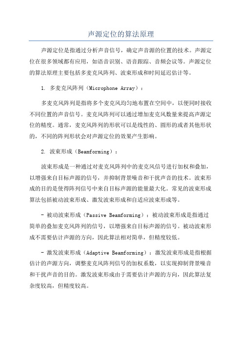
声源定位的算法原理声源定位是指通过分析声音信号,确定声音源的位置的技术。
声源定位在很多领域都有应用,如语音识别、语音跟踪、音频会议等。
声源定位的算法原理主要包括多麦克风阵列、波束形成和时间延迟估计等。
1. 多麦克风阵列(Microphone Array):多麦克风阵列是指将多个麦克风均匀地布置在空间中,以便同时接收不同位置的声音信号。
麦克风阵列可以通过增加麦克风数量来提高声源定位的精度。
通常,麦克风阵列的形状可以是线性的、圆形的或者其他形状的,不同的阵列形状会对声源定位的效果产生影响。
2. 波束形成(Beamforming):波束形成是一种通过对麦克风阵列中的麦克风信号进行加权和叠加,以增强来自目标声源的信号,并抑制背景噪音和干扰声音的技术。
波束形成的目的是使得阵列信号中来自目标声源的能量最大化。
常见的波束形成算法包括被动波束形成、激发波束形成和自适应波束形成等。
- 被动波束形成(Passive Beamforming):被动波束形成是指通过简单的叠加麦克风阵列的信号,以增强来自目标声源的信号。
被动波束形成不需要估计声源的方向,因此算法相对简单,但精度较低。
- 激发波束形成(Adaptive Beamforming):激发波束形成是指根据估计的声源方向,调整麦克风阵列信号的加权系数,以实现抑制背景噪音和干扰声音的目的。
激发波束形成由于需要估计声源的方向,因此算法复杂度较高,但精度较高。
- 自适应波束形成(Adaptive Beamforming):自适应波束形成是指根据实时接收的信号和背景噪音的统计特性,自适应地调整麦克风阵列的加权系数,以实现最优波束形成。
自适应波束形成利用信号处理算法来估计加权系数,从而抑制干扰声音和背景噪音。
3. 时间延迟估计(Time Delay Estimation):时间延迟估计是指通过分析麦克风阵列中不同麦克风接收到的信号之间的时间差,来估计声源的方向。
常见的时间延迟估计算法包括互相关法、基于延迟和和互相关法、最大似然估计法等。
Yealink视频会议解决方案指南说明书

Contact us for more information | Hotline: 0086-592-5702000Businesscooperation:********************Technical inquiries: 2019-05-English-V1.2Guide to Yealink VideoConferencing SolutionYealinkEasy Collaboration, High Productivity Yealink is the global leading provider of unified communication (U C) solutions. It is dedicated in its pursuit of delivering the best possible user experience and the highest customer satisfaction through high-quality, feature-rich and intuitive products. Its international distribution network and strong pre- and after-sales team ensure professional technical support and efficient services.Yealink One-stop UC Solutions unify voice, video and data. They satisfy diverse customer needs and usage scenarios. Together with its partners and distributors, Yealink has acquired a sterling reputation with more than 50 ,000 customers, helping them to overcome meeting difficulties, to face market challenges and to take a lead in market competition by increasing their efficiency and productivity. Yealink has helped to enhance productivity in a wide range of scenarios, including government events like G20 Summits as well as in corporate scenarios in the financial, medical, education and transportation industries.YealinkGlobal PresenceYealink Global Headquarters (Xiamen)Yealink R&D Center (Shenzhen)Yealink AustraliaYealink USA (Atlanta, GA)Yealink USA (San Jose, CA)Yealink R&D Center (Hangzhou)Yealink EuropeTransportation · Emirates · Soekarno-Hatta Airport · Russian Railways · KLM Royal Dutch Airlines · Transoil Enterprise· PWC· Grupo DASS· Altium· TSMC· Amul Government · G20 Peak Summit · The United Nation · BRICS Summit · Supreme Court of Russia · Macao Health Bureau To create easy collaboration workplaces, Yealink solutions are adopted by :Energy· China Sinopec· Rosneft· Natural Gas Financial · Standard Chartered-Indonesia · Bank of Flint Hills · CapMan · China Merchant Bank · Bank ABEPC Education · Saint Petersburg University · University of Johannesburg· Chinese Academy of Sciences Healthcare · Zahrawi · PTS Diagnostics · BestMedAwards2017 CEIA: Best Video Conferencing Solution Innovation Provider 2017 TMC Unified COMMUNICATIONS - Product of the year 2017 CTIFORUM Editor's Choice Award 2016 Best Enterprise Video Conferencing ProductTop 10 Video Conferncing Award 2018 Technology ResellerEditor's Choice Award- Yealink VC2002018 Global IP Desktop Phone Growth Excellence Leadership AwardVideo ConferencingBenefits Travel cost reduced by video conferencing Productivity increased by video conferencing Decisions made in time by video conferencing Benefits to your businessIncrease employee devotion: Video conferencing stands for easy collaboration,which fosters employees' deep devotion to work.Conduct business faster: fast-paced work environment, video conferencing helps speed your collaboration time and your team’s response to market needs.Foster innovation: Video brings people into sharp focus, allowing you to see the impact of your ideas and to boost innovation.Deepen partnerships: Video conferencing allows you to create deeper relationships with your customers and partners whoever and wherever they are.Video ConferencingCreating an Highly Collaborative WorkplaceWhen it comes to evaluating video conferencing system and deciding whether it truly enhances workplace collaboration, the following three aspects play the major roles-user experience, content innovations and interoperability.User experienceA user-friendly video conferencing system is a secret weapon to improve workplace collaboration. However, what would happen if the system itself is hard-to-use? It will actually become another burden in communication, rather than helping it. Usually users from different background would be involved in a meeting. An easy-to-use system with intuitive interface that creates consistent user experience would facilitate the entire collaboration process and lead to higher work efficiency.Content innovationsFace-to-face communication is the basic feature of video conferencing, but it is not enough to simply connect people together. In most cases, users need to do a theme report or discussion. Based on this demand, content sharing and whiteboard features are necessary, allowing people to work together from various locations as though they’re in the same room. InteroperabilitySuch disparity in system and devices might lead to countless communication problems and technical issues, which as a result, damage collaboration and work efficiency. With that said, a qualified video conferencing system should come with strong interoperability that allows users to connect to the broadest range of devices.Yealink constantly innovates to provide easy-to-use, collaborative and interoperable business video conferencing solutions that help enterprises achieve greater business success. The VC800, VC500 and VC200 Room System offer a scalable and secure multipoint video conferencing solution. Yealink has been fully devoted to unremitting innovation through technological advances in order to create the best customer experience ever in video conferencing.Easy-to-use, Collaborative and InteroperableOne-stop Video Conferencing Solutions4K1:00Highest Video QualityOffering a vivid image as well as a clear concentration, with 4K HD camera lensSpectacular SoundDelivering powerful sound and truly stunning meeting experience with Noise Proof TechnologyContent InnovationAllowing users to easily demonstrate every idea via wireless content sharing and whiteboardFast ImplementationDeploying a meeting room in less than 1 minute Joining any meeting in an instant and start screen sharing with the touch of a buttonVC800VC500 VC200CTP20Huddle Meeting Room | 2-6 people Yealink VC200Key Features· Ultra HD 4K camera and 103° angle lens· 6 built-in beamforming microphones with directed voice pickup· Supports smart Noise Proof technology· Supports wireless content sharing, fulfilling wireless deploymentin huddle rooms· All-in-one devices, including codec, camera, mics and bracket· Supports the third-party room system and integrates withthe leading cloud platforms· Supports collaboration features (interoperable with whiteboardand annotation on content sharing)Key Benefits· 1080P high video quality· Automatically filters unrelated noise, video conferencingcan be more concentrated· Deploys huddle room in less than 1 minute· 0 training required· 2-6 participants covered at the same timeWhat’s included· VC200 Codec x1· VCR11 Remote Control x1· AAA Batteries×2· 3m Ethernet Cable x1· 1.8m HDMI Cable (for the display device) x1· PSE x1· 2m Ethernet Cable(CAT5E FTP cable) x1· Power Cord x1Medium Meeting Room | 6-12 people Yealink VC500Key Features· 5x optical PTZ camera and 83°wide-angle lens· Supports smart Noise Proof technology· Supports wireless content sharing, fulfilling wireless deploymentin medium rooms· Supports third-party room systems and integrates with theleading cloud platforms· Camera and codec all-in-one, easy to mount on TV· Supports collaboration features (interoperable with whiteboardand annotation on content sharing)Key Benefits· 1080P high video quality· Automatically filters unrelated noise, video conferencingcan be more concentrated· Hassle-free deployment using just 1 network cable· 0 training required· 50% network cost decreased· 6-12 participants covered at the same time· 2 packages enhance diversity:VC500-Mic or VC500-VCM-CTPWhat’s included· VC500 Codec ×1· VCM34 Video ConferencingMicrophone Array ×1· CTP20 Collocation Touch Panel ×1· WPP20 Wireless Presentation Pod ×1· WF50 USB Wi-Fi Dongle ×1· VCR11 Remote Control ×1· AAA Batteries ×2· Acrylic Board ×1· 1.8m HDMI Cable(for the display device) ×1· 3.0m Ethernet Cable ×2· 7.5m Ethernet Cable ×1· 1.0m USB Type-C Cable ×1· Wall/TV Mounted ShelfwithScrews ×1· Power Adapter ×1Large Meeting Room | 12+ people Yealink VC800Key Features· 12x optical camera· 1+8 cameras solution, powerful multi-camera solution· Supports smart Noise Proof technology· Supports wireless content sharing, fulfilling wirelessdeployment in large rooms· 24-site multipoint and 2 virtual meeting rooms availableat the same time· Supports third-party room system and integrates with theleading cloud platforms· Supports collaboration features (interoperable withwhiteboard and annotation on content sharing)Key Benefits· 1080P high video quality· Automatically filters unrelated noise, videoconferencing can be more concentrated· Hassle-free deployment using just 1 network cable· 0 training required· 50% network cost decreased· 12+ participants covered at the same timeWhat’s included· VC800 Codec ×1· VCM34 Video ConferencingMicrophone Array ×2· CTP20 Collocation Touch Panel ×1· WPP20 Wireless Presentation Pod ×1· WF50 USB Wi-Fi Dongle ×1· VCR11 Remote Control ×1· AAA Batteries ×2· Acrylic Board ×1· 1.8m HDMI Cable(for the display device) ×2· 3.0m Ethernet Cable ×3· 7.5m Ethernet Cable ×1· 1.0m USB Type-C Cable ×1· Wall/TV Mounted ShelfwithScrews ×1· Power Adapter ×1Easy Video Collaboration All in YealinkYealink Meeting Server The Yealink Meeting Server is a distributed cloud-based video conferencing infrastructure tailored for HD video conferencing collaboration in the modern workplace.Video Conferencing Server Yealink Meeting ServerVC880 is designed for ultra-large conference rooms and auditoriums, especially when the control room is separated from the main meeting room.Video Conferencing System VC880Specially designed to optimize communication for in-demand executives and teleworkers, Yealink flagship smart video phone VP59 embodies the future of collaboration.Flagship Smart Video Phone VP59Collaboration Touch Panel CTP20Yealink CTP20 is a smart tool paired with Yealink VC room system. The integrated touchable meeting control, annotation and whiteboard features of CTP20 offers a comfortable and productive collaborative meeting experienceVideo Collaboration Application VC MobileYealink VC Mobile is a powerful and easy-to-use collaboration application, which represents a reliable one-stop solution for remote and mobile workers who want to join high-quality video conferences from their mobile devices wherever they go.Video Collaboration Software VC DesktopYealink VC Desktop is a powerful and easy-to-use collaboration software app for personal use that brings HD video conferencing to you.Huddle RoomVC200Yealink One-stop SolutionsMedium RoomVC500-MicMedium RoomVC500-VCM-CTPLarge RoomVC8001*1*1*up tp24 sites×××2×××√8M Pixels2M Pixels2M Pixels2M Pixels4x digital5x optical5x optical12x optical30FPS60FPS60 FPS60FPS103°83°83°70°×××Support up to1+8 cameras MultipointcapabilityVirtualmeeting roomVoiceactivationPixel Zoom Frame rate HorizontalField of viewMuilti camerasolution Multipoint Camera Feature* Additional five-way audio callup to 1080P30FPSup to 1080P60FPSup to 1080P 60FPSup to 1080P60FPS √√√√1080P from 512kbpsin H.2651080P from 512kbpsin H.2651080P from 512kbpsin H.2651080P from 512kbpsin H.26530%30%30%30%√√√√Video call quality H.265/HEVC Bandwith requirement Video packetloss recoveryLocal HD recordingto USB flash driveBuilt-in beamformingmicrophone arraysVideo ConferencingMicrophone ArrayVideo ConferencingMicrophone ArrayMicrophone Model16ft / 5 meters10ft / 3 meters20ft / 6 meters20ft / 6 metersVoice pickupdistance70%70%70%70%××OptionalMSpeakerOptionalMSpeakerNoise prooftechnologySpeaker Video Features Audio FeaturesWirelessmicrophoneHuddle Room VC200Medium Room VC500-Mic Medium Room VC500-VCM-CTP Large Room VC800Yealink One-stop Solutions Optional Optional up to 4up to 4Collaboration Touch Panel Collaboration Features√√√√Touchscreen √√√√Local collaboration √√√√Meeting collaboration Optional 2.4GHz/5GHz dual mode Optional Optional Wi-Fi optional Bluetooth 4.2optional optional Bluetooth IPv4/IPv6IPv4/IPv6IPv4/IPV6IPv4/IPv6TCP/IPNetwork & Security H.323/SIP H.323/SIP H.323/SIP H.323/SIP Communication protocols ICE/TURN/STUN/NAT/H.460ICE/TURN/STUN/NAT/H.460ICE/TURN/STUN/NATH.460ICE/TURN/STUN/NATH.460Traversal features SRTP/TLS/H.235/AES 256-BIT SRTP/TLS/H.235/AES 256-BIT SRTP/TLS/H.235/AES 256-BIT SRTP/TLS/H.235/AES 256-BIT Encryption H.265/HEVC, H.264 High Profile, H.264, H.263, H.263+H.265/HEVC, H.264 High Profile, H.264, H.263, H.263+H.265/HEVC, H.264 High Profile, H.264, H.263, H.263+H.265/HEVC, H.264 High Profile, H.264, H.263, H.263+Video Codec ARES, Opus(8-48kHz), G.722.1c, G.722.1, G.722, G.711(PCMU/PCMA)ARES, Opus(8-48kHz), G.722.1c, G.722.1, G.722, G.711(PCMU/PCMA)ARES, Opus(8-48kHz), G.722.1c, G.722.1, G.722, G.711(PCMU/PCMA)ARES, Opus(8-48kHz), G.722.1c, G.722.1, G.722, G.711(PCMU/PCMA)Audio Codec 1080P, 720P, 540P, 360P, 4CIF, CIF 1080P, 720P, 540P, 360P, 4CIF, CIF 1080P, 720P, 540P, 360P, 4CIF, CIF 1080P, 720P, 540P, 360P, 4CIF, CIF Video resolution。
- 1、下载文档前请自行甄别文档内容的完整性,平台不提供额外的编辑、内容补充、找答案等附加服务。
- 2、"仅部分预览"的文档,不可在线预览部分如存在完整性等问题,可反馈申请退款(可完整预览的文档不适用该条件!)。
- 3、如文档侵犯您的权益,请联系客服反馈,我们会尽快为您处理(人工客服工作时间:9:00-18:30)。
The distance from source to Ref Mic: d = 30 in.
The distance from source to Mic x: g = 34.73 in. The distance between mic: N = 17.5 in. Sampling Frequency: fs = 22050 samples/sec. Speed of sound: c = 345 m/sec. Find d’ = 34.73 – 30 = 4.73. Find Sample/meter => 22050/345 = 63.913 samples/m. Turn into inches => 63.913 x 0.0254 = 1.62 To find time delay, we need distance d’ x = 4.73 x 1.62 = 7.7 samples, round up to be 8 samples.
Solution and Approach
Results
Conclusion
Introduction
The goals for the project are the following
Learn the basic concept of microphone array Become familiar and learn how to use a program that
The general form of the beamforming output based on
delay and sum
Beamforming Pattern
Signal to Noise Ratio
The measurement of the signal quality
Basically, it is the magnitude of
Therefore, there is a time delay in each signal.
Microphone Array
Multi-Cቤተ መጻሕፍቲ ባይዱannel Signal Comparison
Time Delay
Note that the distance between another microphone (not the reference) to the source, which denote as g, can be compute with trigonometry cos = d/g => d = g cos.
depend on the application. Line Circle Rectangle
Each microphone will capture the sound from the
source at the different time due to distance from the source.
Since signals from the specified source are on the
same phase, they will add each other up.
The noise signals may either add each other up or
cancel each other out.
Example of Microphone Array
Beamforming
A technique that rearrange the mixture signals from the
microphone array, so that the signals from the source that we want are lined up before combine them all up into one signal
Voice Activity Detection
perform Beamforming Show that Beamforming will enhance the signal quality based on SNR
Microphone Array
Multiple microphones set up in certain formation
signal noise
One way to calculate it is to find noise from voice activity detection 1. Measure the mean of the energy during the last t1 seconds => E1 2. Measure the mean of the energy during the last t2 seconds => E2 3. Calculate the speech threshold T2 = E2 + Ex 4. If E1 > Ts, speech is detected. (speech onset) 5. Freeze E2 and calculate the noise threshold Tn = E2 + En 6. Measure the mean of the energy of recent t1 seconds => E1 7. IF E1 < Tn, noise is detected. (speech offset)
Microphone Array and Beamforming
By Pattarapong Rojanasthien ECE 5525 Dr. Kepuska December 8th, 2008
Overview
Introduction Background
Microphone Arrays Beamforming Signal to Noise Ratio