MATCH-AT用户操作手册
海尔电子(Siemens)机器人式洗衣机操作手册说明书

2. Scan the QR code with the Home Connect app.
Hardness mmol/l range
Soft
0 - 1.1
Setting value
H:00
Soft
1.2 - 1.4 H:01
Setting the water softening system
1. Press . 2. To open the basic settings, press
Medium 2.2 - 2.9 H:04
A table of country-specific units can be found in the instruction manual.
Hard Hard
3.0 - 3.7 H:05 3.8 - 5.4 H:06
Hard
5.5 - 8.9 H:07
6. Re-assemble the filter system.
7. Insert the filter system into the appliance and turn the coarse filter clockwise. Make sure that the arrow markings match up.
50 ml
2. Close the lid of the deter-
25 ml
gent dispenser.
15 ml
a The lid clicks into position.
Programmes
The programme data has been measured in the laboratory according to European standard EN 60436. The consumption figures depend on the programme and additional function selected. The runtime will change if the rinse aid system is switched off or rinse aid needs to be added.
Kodak M575相机用户操作手册说明书

ᕡAttach the strap, load the batteryKLIC-7006batteryᕢCharge the batteryCharge the battery whenever necessary.Battery Charging light:• Orange: charging • Green: finished2121Your plug may differ.Turn off the camera.Connect the KODAK Camera USB Cable, Micro B /5-Pin and charger. (Use only the cable included with this camera!)Battery Charging light:• Blinking: charging • Steady: finishedIf your package includes a charger:If your package includes an adapter:Your adapter may differ.ᕣTurn on the cameraᕤSet the language and date/timeSee the Extended user guide /go/m575supportto change current field.for previous/next field.OK to accept.At the prompt, press OK.to change.OK to accept.Language :Date/Time:See other modes page 10See the Extended user guide /go/m575support(If it’s in a different mode, press the Mode button,thento choose Smart Capture 2Press the Shutter buttonhalfway to focus and set exposure.When the framing marks turn green, press the Shutter button completely down.Compose the picture.3Mode buttonThen press OK.).ᕦReview pictures/videosSee the Extended user guide /go/m575supportView previous/next picture/video.Press the Reviewbutton to enter/exitReview.Play a video.OK Review12ᕧDownload software, transfer picturesWhen you connect the camera to the computer, it prompts you to run the KODAK Software Downloader on your computer. Make sure the computer is connected to the Internet. When you connect the camera to the computer, the KODAK Software Downloader automatically runs. Follow the prompts to download and install KODAK Software.1Turn off the camera.2Use the KODAK Camera USB Cable, Micro B / 5-Pin to connect camera to computer. (Use only the cable included with this camera!)3Turn on the camera.4After the software isinstalled, follow the prompts to transfer pictures and videos to your computer.NOTE: If the downloader does not run, find it here and launch it:■WINDOWS OS: in My Computer ■MAC OS: on your DesktopDownload KODAK Software /go/camerasw To use this camera on more than one computerSee the Extended user guide at /go/m575supportᕨUse the camera Help systemKeep learning about your camera!See the Extended user guide /go/m575supportScroll through a Help topic.then highlight a menu choice.Press the Info1button.2Press the Menu button ,Go to /go/m575support for:• the Extended user guide• interactive troubleshooting and repairs • interactive tutorials • and more!Front ViewLens Self-timer/ Video light/ AF Assist LightSpeakerMicrophoneFlashBack ViewOK, Wide Angle/Telephoto button Battery compartment SD/SDHC Card slotTripod socketLCDShare buttonUSB port Power button Flash button Mode button Shutter buttonDelete, Menu, Info buttonsStrap postReview button1Do more with your cameraPress the Mode button, thento choose the mode that best suits your subjects and surroundings, then press OK .Adjust LCD brightnessTo adjust the LCD brightness for your environment, see the Extended user guide (/go/m575support ).Mode buttonUse this modeForSmart Capture General picture taking—excellent image quality and ease of use.Program Advanced picture taking—allows access to manual settings.ScenePoint-and-shoot simplicity when taking pictures in practically any situation. (See page 11.)VideoCapturing video with sound. (See page 11.)Do more with your cameraTake a video1Press the Mode button, thento choose Video, then press OK.2Press the Shutter buttoncompletely down,then release it. To stoprecording, press and releasethe Shutter button again. Use Scene (SCN) modesChoose a Scene mode—for great pictures in any situation.1Press the Mode button, then to choose SCN, then press OK.2Press to choose a mode and read its description.3Press OK (or let the description turn off) to enter the chosen Scene mode.To read a mode description after it has turned off, press OK. SCN modes: Portrait, Sport, Panorama (L-R, R-L), Landscape, High ISO, Close-up, Flower, Sunset, Backlight, Candle Light, Children, Manner/Museum, Text, Beach, Snow, Fireworks, Self-Portrait, Night Portrait, Night Landscape, Panning Shot.Do more with your cameraUse the flashPress the Flash button Flash buttonrepeatedly until the LCDdisplays the desired flashmode.PreflashCorrectionDo more with your cameraUse the optical zoom1Use the LCD to frame yoursubject.2To zoom in, press Telephoto(T). To zoom out, press WideAngle (W).3Take the picture.Use shortcutsYour camera has a clean, uncluttered interface. For quick access to the most popular capture and review functions:1Press the Info button.The shortcuts appear. To hide the shortcuts again, press .2Press to access functions like Exposure Compensation, Self-timer, and Auto focus. (You’ll see different functions in different modes.)3Press to choose a setting.Press to show/hide shortcuts.ShortcutsDo more with your cameraDelete pictures/videos1Press the Review button.2Press for previous/next picture/video.3Press the Delete button.4Follow the screen prompts.Use the menu button to change settings You can change settings to get the best results from your camera. Some modes offer limited settings.1Press the Menu button.2Press to choose a tab:■Capture/Video for the most common picture- and video-taking settings■Setup for other camera settings3Press to choose a setting, then press OK.4Choose an option, then press OK.To access the camera Help system, see page7.Do more with your cameraUnderstand the picture-taking icons Understand the review iconsBattery level Pictures/timeremainingZoom sliderCapture mode Keyword tag Self timer/BurstFlash modeFocus modeExposure compensationFavoriteUploadVideo durationSelectpicture/videoText tag Add text tagEmail Print/number of prints Protected Picture/Video numberBattery level Play videoView thumbnails2Share and tag picturesIt’s never been easier to share pictures on your favorite social networking sites.IMPORTANT: To use the camera social networking features, you need to download KODAK Software. (See page6.)1Press the Review button, then to find a picture.2Press the Share button.If it’s your first time, a Help screen appears.3Press to choose a social networking site, then press OK.A check mark appears. Repeat this step to choose more sites.(Press OK again to remove a check mark.)4Press to choose Done, then press OK.The picture is displayed with the Share icon. When you transfer the picture to your computer, it will be sent to the networking site(s) that you chose.Tip: Do you send pictures to the same sites each time?Find a picture, then press and hold the Share button for about 1 second.The camera applies the networking site(s) that you used previously and adds the Share icon to the picture.Share and tag pictures Choose networking sites to showYou can show/hide social networking sites on your camera so that only your favorite sites appear.1In Review, press the Menu button.2Press to choose the Setup tab, then to chooseShare Button Settings, then press OK.3Press to choose a social networking site, then press to choose Show/Hide. Repeat this step for eachnetwork.4When finished, press to choose Done, then press OK.To return to picture-taking mode, press the Shutter buttonhalfway down. When you are in Review and press the Share button, your chosen sites appear.To access the camera Help system, see page7.Share and tag picturesManage email addresses and KODAK PULSE Digital FramesYou can add, edit, or delete email addresses and KODAK PULSE Digital Frames on your camera.1In Review, press the Share button. Press to choose Manage Email Addresses (or Manage Frames), then press OK.2To add an email address or frame, press to choose New Email or New Frame, then press OK. Use the on-screen keyboard to make the addition.(Example:******************)To edit an email address or frame, press to choose the address’s nickname (“Dad” or “Mary”) or the frame, then press OK. Use the on-screen keyboard to make edits.To delete an email address or frame, choose Delete Email or Delete Frame, then press OK. Press to choose theaddress or frame, then press OK so that a check markappears. Press to choose Delete, then press OK.3When finished, press to choose Done, then press OK.Share and tag pictures Use the keyboardThe keyboard appears when you need it.1Press to choose a letter, then press OK.2When finished, press to choose OK, then press OK. 3If you’ve added a new name, the camera prompts you to update all faces to match assigned names. Choose Yes, then press OK.The name is assigned to all faces that match this one.Tag picturesTag pictures to make them easy to find, later. You can tag pictures in 2 ways:■People, and then find all pictures of “Mary.”■Keywords, and then find all pictures from “Dad’s 60th Birthday.”Share and tag picturesTag peopleWhen you tag faces, you’re helping your camera to recognize people by name. Then it matches names and faces to pictures you’ve taken—and those you take in the future!1Press the Review button, then to find a picture that contains faces.2Press the Menu button. Press to choose TagPeople, then press OK.3Press to choose Apply Tags, then press OK.4Press to choose an existing name, or New Name to add a new one, then press OK.If more than one face is detected, a name or question mark is assigned to each detected face. To resolve an incorrect name ora question mark, press to select a face, then press OK. 5If prompted to Update People Tags, press to choose Yes, then press OK.Other pictures are scanned and updated with the name(s) you applied here.Press to add names to other pictures. When finished, pressto choose Done, then press OK. To return to picture-taking mode, press the Shutter button halfway down. To access the camera Help system, see page7.Share and tag picturesNeed to update a name?If you meet a new friend—James—but you already have pictures tagged with an old friend, James, you can:■Tag the new James with “James Smith” and/or■Update the old James to “James Monroe”1Press the Review button.2Press the Menu button. Press to choose TagPeople, then press OK.3Press to choose Modify Names List, then press OK. 4Press to choose the name you want to modify, then press OK.5Edit the name, press to choose OK, then press OK. (If prompted to Update People Tags, press to choose Yes, then press OK.)To return to picture-taking mode, press the Shutter buttonhalfway down.NOTE: You can have up to 20 active names.To access the camera Help system, see page7.Share and tag picturesTag with keywords1Press the Review button, then to find a picture.2Press the Menu button. Press to choose KeywordTag, then press OK.3Press to choose an existing keyword or New Keyword to add a new one, then press OK.4Press to add keywords to other pictures. When finished,press to choose Done, then press OK.To return to picture-taking mode, press the Shutter buttonhalfway down.Tip: You can pre-choose a tag so that new pictures/videos are assigned that tag. See the Extended user guide at/go/m575support.To access the camera Help system, see page7.Share and tag pictures A smarter way to find your picturesTag pictures—by people or keywords—to make them easy to find, later. For example, the camera can find all pictures that contain “Mary” or “Dad’s 60th Birthday.” (See Tag people, page 20 or Tag with keywords, page 22.)1Press the Review button.2Press the Wide Angle (W) button to view pictures by thumbnail (or choose View Thumbnails shortcut).3Press to choose a tab and sort pictures by All,Date, People, Favorite, or Keyword.4Press to choose a picture or picture stack.Press Telephoto (T) to see pictures in a stack or to see an individual picture. Press Wide Angle (W) to see thumbnails or picture stacks. To return to picture-taking mode, press the Shutter button halfway down.KeywordsFavorites PeopleDate AllFor best results, make sure thecamera date/time is current.3Solve camera problemsTo access the camera Help system, see page7.Go to /go/support to see the Extended user guide and for Step-by-Step Solutions & Repair.4AppendixCAUTION:Do not disassemble this product; there are no user-serviceable parts inside. Refer servicing to qualified service personnel. KODAK AC Adapters and Battery Chargers are intended for indoor use only. The use of controls, adjustments, or procedures other than those specified herein may result in exposure to shock and/or electrical or mechanical hazards. If the LCD breaks, do not touch the glass or liquid. Contact Kodak customer support.■The use of an accessory that is not recommended by Kodak may cause fire, electric shock, or injury. For approved accessories, go to /go/accessories.■Use only a USB-certified computer equipped with a current-limiting motherboard.Contact your computer manufacturer if you have questions.■If using this product in an airplane, observe all instructions of the airline.■When removing the battery, allow it to cool; it may be hot.■Follow all warnings and instructions supplied by the battery manufacturer.■Use only batteries approved for this product to avoid risk of explosion.■Keep batteries out of the reach of children.■Do not allow batteries to touch metal objects, including coins. Otherwise, a battery may short circuit, discharge energy, become hot, or leak.■Do not disassemble, install backward, or expose batteries to liquid, moisture, fire, or extreme temperature.■Remove the battery when the product is stored for an extended period of time. In the unlikely event that battery fluid leaks inside the product, contact Kodak customersupport.■In the unlikely event that battery fluid leaks onto your skin, wash immediately with water and contact your local health provider. For additional health-related information, contact your local Kodak customer support.■See /go/reach for information about the presence of substances included on the candidate list according to article 59(1) of Regulation (EC) No.1907/2006 (REACH).■Dispose of batteries according to local and national regulations. Go to /go/kes.■Do not charge non-rechargeable batteries.For more information on batteries, see /go/batterytypes.Limited WarrantyKodak warrants its digital cameras and accessories (excluding batteries) to be free from malfunctions and defects in both materials and workmanship for the warranty periodAppendixspecified on your KODAK Product packaging. Retain the original dated sales receipt. Proof of purchase date is required with any request for warranty repair.Limited warranty coverageWarranty service is only available from within the country where the products were originally purchased. You may be required to ship products, at your expense, to the authorized service facility for the country where the products were purchased. Kodak will repair or replace products if they fail to function properly during the warranty period, subject to any conditions and/or limitations stated herein. Warranty service will include all labor as well as any necessary adjustments and/or replacement parts. If Kodak is unable to repair or replace a product, Kodak will, at its option, refund the purchase price paid for the product provided the product has been returned to Kodak along with proof of the purchase price paid. Repair, replacement, or refund of the purchase price are the sole remedies under the warranty. If replacement parts are used in making repairs, those parts may be remanufactured, or may contain remanufactured materials. If it is necessary to replace the entire product, it may be replaced with a remanufactured product. Remanufactured products, parts and materials are warranted for the remaining warranty term of the original product, or 90 days after the date of repair or replacement, whichever is longer.LimitationsThis warranty does not cover circumstances beyond Kodak’s control. This warranty does not apply when failure is due to shipping damage, accident, alteration, modification, unauthorized service, misuse, abuse, use with incompatible accessories or attachments (such as third party ink or ink tanks), failure to follow Kodak’s operation, maintenance or repacking instructions, failure to use items supplied by Kodak (such as adapters and cables), or claims made after the duration of this warranty. Kodak makes no other express or implied warranty for this product, and disclaims the implied warranties of merchantability and fitness for a particular purpose. In the event that the exclusion of any implied warranty is ineffective under the law, the duration of the implied warranty will be one year from the purchase date or such longer period as required by law. The option of repair, replacement, or refund is Kodak’s only obligation. Kodak will not be responsible for any special, consequential or incidental damages resulting from the sale, purchase, or use of this product regardless of the cause. Liability for any special, consequential or incidental damages (including but not limited to loss of revenue or profit, downtime costs, loss of the use of the equipment, cost of substitute equipment, facilities or services, or claims of your customers for such damages resulting from the purchase, use, or failure of the product), regardless of cause or for breach of any written or implied warranty is expressly disclaimed. The limitations and exclusions of liability set forth herein apply to both Kodak and its suppliers.Your rightsSome states or jurisdictions do not allow exclusion or limitation of incidental or consequential damages, so the above limitation or exclusion may not apply to you. Some states or jurisdictions do not allow limitations on how long an implied warranty lasts, so the above limitation may not apply to you. This warranty gives you specific rights, and you may have other rights which vary from state to state or by jurisdiction.Appendix Outside the United States and CanadaIn countries other than the United States and Canada, the terms and conditions of this warranty may be different. Unless a specific Kodak warranty is communicated to the purchaser in writing by a Kodak company, no warranty or liability exists beyond any minimum requirements imposed by law, even though defect, damage, or loss may be by negligence or other act.FCC compliance and advisoryThis equipment has been tested and found to comply with the limits for a Class B digital device, pursuant to Part 15 of the FCC Rules. These limits are designed to provide reasonable protection against harmful interference in a residential installation. The KODAK High Performance USB AC Adapter K20-AM complies with part 15 of the FCC Rules. Operation is subject to the following two conditions: (1) This device may not cause harmful interference, and (2) this device must accept any interference received, including interference that may cause undesired operation.Canadian DOC statementDOC Class B Compliance—This Class B digital apparatus complies with Canadian ICES-003.Observation des normes-Classe B—Cet appareil numérique de la classe B est conforme à la norme NMB-003 du Canada.China RoHSVCCI Class B ITEAustralian C-TickN137AppendixKorean Class B ITEKorean Li-Ion RegulatoryEastman Kodak CompanyRochester, New York 14650© Kodak, 2009Kodak, EasyShare, and Pulse are trademarks of Eastman Kodak Company. 4H6902_en。
MOTOROLA MICOM中文使用手册
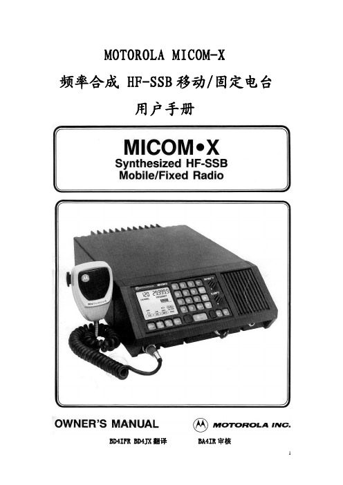
4. 接收声音信号时,可调节 CLARIFIER 使声音自然。本调节对发射频率无效。 5. 电台会保持上次使用的信道,下次开机自动进入。 6. 键盘按动到位时有啪哒感。不要用尖锐物按键以免损坏。 7. 信道选择。两种不同的选择方式:上下箭头和数字键。
钮或按麦克风上的 PTT 键。要扫描少于 10 个信道,在 101 到 110 信道之间不感兴趣的信道 中通过编入 0 来去除其中的频率信息。按 RESET 返回按 SCAN 钮之前使用的信道。
8. 发射 a. 在发射之前先收听。关闭静噪。SQ 钮右上角的灯熄灭。如果是半双工信 道,按 TX/RX 钮监听发射频率的情况。方框将围绕着‘XMIT’直到再 按 RX/TX 钮,或 PTT 钮按下并释放,或 60 秒重设定时器重新设置控制。 如果这信道或频率没人用,扬声器中将听到噪声。如果有人使用,应当改 变信道或等待。 b. 正确握持麦克风 稳定的握住麦克风,网格面对嘴唇约 5cm 距离。 c. 讲话清楚并缓慢 充分按下麦克风侧面的 PTT,功率表图示下面的下划线 出现。如果这信道是单工(收发同频),显示的频率不会改变。如果信道 是半双工(收发不同频),平时显示的是接收频率,PTT 按下去时显示的 是发射频率。用普通声音清楚地缓慢地讲话。说话时观察 RF 功率图示。 产生的 RF 输出大约显示从左至右每一个柱形为 15W 增量。如果天线系 统调谐不合适,产生的反射功率通过从左至右熄灭柱形显示来指示。见下 面图示。
1. 模式 选择下列发射类型之一:SSB,AME。或 PILOT。
2. USB/LSB (可选)选择上边带或下边带用于发射和接收。
3. TX/RX 选择单工(SMPX)或半双工(RCV & XMIT)操作模式。在半双工模式 时也允许监视发射频率。
Pocket Pro II 操作手册说明书

815.874.8001 • OPERATING INSTRUCTIONSPlease read this manual!This manual contains setup information necessary to achieve proper performance from your Pocket Pro II.(gray model# CEI-4710)(blue model# CEI-4700)1Table of ContentsBattery Installation . . . . . . . . . . . . . . . . . .2Automatic Shutdown . . . . . . . . . . . . . . . .2Forced Shutdown . . . . . . . . . . . . . . . . . . .2Quick Start! . . . . . . . . . . . . . . . . . . . . . . . . . .3Control Buttons . . . . . . . . . . . . . . . . . . . . .3Shot Detection . . . . . . . . . . . . . . . . . . . . . .4Shot Review Screen . . . . . . . . . . . . . . . . . .4Setting the PAR Time (second beep) . . .5Setting the Start Delay . . . . . . . . . . . . .5-6Display Backlighting . . . . . . . . . . . . . . . . .6Beeper Volume . . . . . . . . . . . . . . . . . . . . . .7Setting the Main Display Type . . . . . .7-8Shot Dead Time . . . . . . . . . . . . . . . . . . . . .9Shot Sensitivity . . . . . . . . . . . . . . . . . . . . . .9Setting the Date and Time . . . . . . . . . .10Battery Status . . . . . . . . . . . . . . . . . . . . . .11Resetting Factory Defaults . . . . . . . . . .11Timer “Wraparound” . . . . . . . . . . . . . . . .12Accuracy . . . . . . . . . . . . . . . . . . . . . . . . . . .12Specifications . . . . . . . . . . . . . . . . . . . . . .13Carrying Case . . . . . . . . . . . . . . . . . . . . . .13Limited Warranty . . . . . . . . . . . . . . . . . . .142Battery InstallationThe Pocket Pro II operates on a 9 volt alkaline battery . It is important to use alkaline batteries due to the power demand of the buzzer . To install the battery, remove the cover, connect the battery to the wire clip, fit the battery in the compartment, and replace the cover . Once installed, the Pocket Pro II will briefly display a sign-on message, followed by the main operating screen . The sign on message can be bypassed by pressing one of the menu buttons .If at any time you suspect the unit is not functioningnormally, try resetting it . The procedure is listed on page 11 of this manual .Automatic ShutdownIf no shots are detected and no buttons are pressed for a period of ten minutes, the timer will power down automatically . This will prevent battery discharge in the event it is not turned off after use . To wake up the timer, press the SET/ON button .Forced ShutdownTo turn the Pocket Pro II off, press and hold the MENU DOWN button for approximately 3 seconds .Quick Start!If you want to get started right away, all you have to do is press the start button on the side and shoot . The Pocket Pro II comes from the factory configured and ready to run . After the timer shuts down, press the SET/ON button to turn it on .Control ButtonsThere are four buttons on the front of the case . Looking at the front of the case,you will see the MENU UP/DOWN buttons on the left, and the SET UP/DOWN value buttons on the right .MENU UP/DOWNThe MENU UP/DOWN buttons are used tonavigate forward and backward through ashort loop of menu screens where the usercan access information and settable values .SET UP/DOWNIn menu screens with flashing settable values,pressing the SET (up arrow symbol) willincrease the value and SET/ON (down arrowsymbol) will decrease the value .MENUShot DetectionEach time a shot is detected, it will be added to the “shot string” maintained within the timer . The timer will automatically calculate the “split time .” Split time is the time between the current shot and the previous shot . The timer can store up to 99 shotsfor a given timing cycle . Subsequent shots will be stored by overwriting the previous value of shot 99 .Shot Review ScreenShots will be displayed on the shot review screenin a “one shot per line” format . Reading from leftto right in the shot line, the shot time appearsfirst, followed by the shot number, and finallythe split time, if any . When first navigating to theshot review screen after the start of a cycle, thefirst shot will appear on the 3rd line, and the lastshot will appear on the 2nd line, if there are 4 or more shots . Otherwise, the shots will be clearly identified by their shot numbers . Use the SET UP/DOWN buttons to scroll through the shot string .SPL 0.25SPL 0.35SPL 1.84SPL 0.844.00 # 54.35 # 61.84 #12.68#25Setting the PAR Time (second beep)The par time setting (also known as the “second beep”) comes configured from the factory for 0 seconds . When the par time is set to 0, the timer will beep only once, at the start of a timing cycle . Setting the par time to other than 0 will give you a beep at the start, and the end of the par time period . Par time is adjustable from 0 to 199 .9 seconds . Hold the SET UP or SET DOWN button to increase the speed at which the digits increment for large par times . Press the SET UP and SET DOWN buttons simulta-neously to reset the Par Time to zero .Setting the Start DelayThe start delay is completely configurable . If enabled, it can generate a fixed delay or random delays between .5 seconds and 9 .9 seconds . The timer is set to a factory default delay time between 1 and 4 seconds .Instant (No Delay)Using the MENU UP/DOWN buttons, advance to the “START DELAY TYPE” screen . Use the SET UP or SET DOWN button to select “ INSTANT .” The timer will start instantly when you press the start button .6Fixed DelayUsing the MENU UP/DOWN buttons, advance to the “START DELAY TYPE” screen . Use the SET UP or SET DOWN button to select “RANDOM”, then press the MENU UP button to advance to the “RANDOM START TIME – MINIMUM” and “RANDOM START TIME – MAXIMUM” display screens . In both screens, select the same delay time (between .5 seconds and 9 .9 seconds) . This will result in a fixed delay time at the setting specified . If you attempt to set a minimum time greater than the current maximum time, or a maximum time less than the current minimum time, the alternate time value will be “pushed” to match the setting currently being adjusted .Random DelayUsing the MENU UP/DOWN buttons, advance to the “START DELAY TYPE” screen . Use the SET UP or SET DOWN button to select “RANDOM” . Then press the MENU UP button to advance to the “RANDOM START TIME – MINIMUM” and “RANDOM START TIME – MAXIMUM” display screens . For each screen, select the desired minimum and maximum delay time to create a start delay “window” of time .Display BacklightingUse the SET UP/DOWN buttons to set the number of seconds (from 0 to 99) the display backlighting will remain on . Setting the value to zero will turn it off . To activate the backlight, press any button . If you would like to illuminate the current display, press the MENU UP , then MENU DOWN button . Longer periods with the7backlight turned on will shorten battery life .Beeper VolumeThe beeper volume can be adjusted by pressing the SET UP or SET DOWN button . Changes are indicated by a “bar graph” display indicator as well as a sample of the sound level . A new setting will be saved automatically .Setting the Main Display TypeThe Pocket Pro II can be configured to show three different types of main displays . These are selected from the “MAIN SCREEN TYPE” menu, and are described below .Review DirectWhen the “Review Direct” main display is selected, the last split time will appear in the upper right hand corner of the main display . Pressing either the SET UP or SET DOWN button will jump directly to the shot review screen . Pressing the MENU UP button will return to the main display screen .8“RPM” ModeWhen the “Rounds per Minute” main display isselected, the Pocket Pro II no longer displays shot times, but now will display rounds per minute . To use this mode, press the START button . After the beep, fire shots; the timer will display the rounds per minute based on the number of shots and the time between the first shot and the last . Shotsrecorded more than 199 .99 seconds after the start beep will render readings invalid until START is pressed again . The normal shot dead time setting is overridden when in RPM mode and set to a fixed value of 0 .032 seconds . This allows the Pocket Pro II to detect shots at rates of up to 1800 RPM . (NOTE: Please see Accuracy on page 12)Single Time OnlyWhen the “Single Time Only” main display isselected, the current shot time appears on the main display and is sized to fill up the screen . Pressing either the SET UP or SET DOWN button will jump directly to the shot review screen . Pressing the MENU UP will return to the main display screen .9Shot Dead TimeThe SHOT DEAD TIME feature is used to reduce false shot recordings due to echoes or ringing . Once a shot is detected, the Pocket Pro II will disregard subsequent shots for a short period of time . The default setting is .11 seconds, but can be adjusted from .05 to .12 seconds . If your split time between shots is less than .11 seconds, an adjust-ment will be necessary . Navigate to the SHOT DEAD TIME display using the MENU UP/DOWN buttons and adjust as needed . The shot dead time setting is set to a fixed value of .032 seconds when in the RPM mode .Shot SensitivityShot sensitivity is variable between 0 and 25 and is settable from the SHOT SENSITIV-ITY screen . Use the SET UP/DOWN buttons to adjust the value . Increase the value for greater sensitivity; decrease it for less sensitivity . Keep in mind that higher sensitivity settings will also increase the chance of false shot detection from handling, vibration, or other noise sources .10Setting the Date and TimeUsing the MENU UP/DOWN buttons, cycle through the MONTH, DAY, YEAR, HOURS, and MINUTES display screens using the SET UP/DOWN buttons to set the date and time . To synchronize to the nearest second, set the “MINUTES” value and at the mark, advance to the next/previous display screen . Internally, the timer will be set to 0 seconds at the instant you change to a different menu screen . Be sure to note the AM/PM setting on the hours screen . The timer will usually retain time and date settings when changing batteries if the change is done as quickly as possible . However, if the battery is removed and not replaced immediately, time/date information is lost and must be reset .11Battery StatusBattery Status can be monitored in two places . On the main screen, a battery icon appears in the lower right-hand corner of the display . As the battery discharges, the icon will become more and more “hollow .” For a more detailed display of the battery condition, press the MENU UP or DOWN buttons repeatedly until the “battery condition” display appears . Here, you can see an expanded “bar graph” type display of the battery level . The timer will operate normally down to a reading of around 6V . When the battery becomes depleted to approximately 6 .5 volts, the display backlighting will be turned off to conserve power . This will allow the session to continue in the event a replacement battery is not readily available . When the battery voltage becomes depleted to less than 6 volts, the Pocket Pro II will shut down to avoid undefined operation .Resetting the Timer to Factory DefaultsTo reset factory default values within your timer, remove the battery, then hold down the “Start” button and reinstall the battery . Look at the display to see the message “INIT N/V MEMORY” . Now release the start button and the reset is complete .ICON12Timer “Wraparound”Internally, the timer is continuously counting up to 199 .99 seconds and then “wrapping around” to 0 . When the start button is pressed, this internal time is reset to 0 . This means that the maximum timing period is limited to 199 .9 seconds . Shots recorded after this will reflect the “wrapped” time . Splits are calculated correctly, as long as the timer has wrapped around only once since the start of the cycle .AccuracyThe Pocket Pro II measures internally to a resolution of 1 mSec, but shot displays, splits, etc . are internally rounded to the nearest 10 mSec . For this reason, RPM readings may appear to be inaccurate when manually calculated using the displayed shot string values . In reality, the RPM reading is actually more accurate than the manual calculation since it is calculated using the internal shot times, which are measured with 1mSec resolution .13Specifications• Operating temp range: 32-110 deg . F .• Accuracy: Quartz crystal controlled . (Within 1/100 second)• Max # of shots stored:99• Max rounds per minute: 1800• Battery type: 9 volt alkalinePocket Pro II Carrying Case• This handy case will protect your timer during transport and storage .• It features a zipper storage compartment for spare batteries, velcro belt strap, and a Competition Electronics embroidered logo .To Order Call 815-874-8001 or visit our website at(model# CEI-4707)14Limited Warranty* * * * * * * * * * * * * * * * * * * * * * * * * * * * * * * * * * * * * * * * * * * * * * * * * * * * *COMPETITION ELECTRONICS, INC., warrants the Pocket Pro II manufactured by it to be free from defects in material and work-manship for a period of 2 years from date of purchase by the original purchaser for use. COMPETITION ELECTRONICS, INC., at its option, will repair or replace without charge, or refund the purchase price of, any product which fails during the warranty period by reason of a defect in material or workmanship found upon examination by COMPETITION ELECTRONICS, INC., to have been the cause of the failure. This warranty does not cover any failures attributable to abuse, mishandling, and failure to follow operating instructions, alteration or accident.To make claim under this warranty, the purchaser must return the product to COMPETITION ELECTRONICS, INC., at the address shown below, properly packed and with shipping charges prepaid. All claims must be made within (30) days after the product failure and, in any event, within thirty (30) days after the expiration of the 2-year warranty. All claims must be accompanied by a sales slip or other written proof of date of purchase.TO THE EXTENT PERMITTED BY LAW, ANY AND ALL IMPLIED WARRANTIES, INCLUDING MERCHANTABILITY AND FITNESS FOR PARTICULAR PURPOSE, ARE EXCLUDED; ANY IMPLIED WARRANTIES NOT EXCLUDED ARE LIMITED IN DURATION TO 2 YEARS FROM DATE OF PURCHASE. INCIDENTAL AND CONSEQUENTIAL DAMAGES ARE EXPRESSLY EXCLUDED FROM THE REMEDIES AVAILABLE TO THE PURCHASER, AND THE REMEDIES PROVIDED IN THIS WARRANTY SHALL BE EXCLUSIVE TO THE EXTENT PERMITTED BY LAW.(Note: Some states do not allow limitations on how long an implied warranty lasts or the exclusion or limitation of incidental or conse-quential damages, so the foregoing limitations and exclusions may not apply to you. This warranty gives you specific legal rights, and you may also have other rights which vary from state to state.)If any product returned by the purchaser is found by COMPETITION ELECTRONICS, INC., to require service not covered by warranty, COMPETITION ELECTRONICS, INC., will so advise the purchaser and request further instructions. COMPETITION ELECTRONICS, INC., will recondition to working order any Pocket Pro II returned to it regardless of condition upon the purchaser’s remittance of payment of 1/2 of current retail price, if it is still manufactured by COMPETITION ELECTRONICS, INC.* * * * * * * * * * * * * * * * * * * * * * * * * * * * * * * * * * * * * * * * * * * * * * * * * * * * *Return Shipping Address:Competition Electronics, Inc . 3469 Precision Dr . Rockford, IL 61109Contact Us:Phone: 815-874-8001 FAX: 815-874-8181 Rev 8-2019User Manual / Operating Instructions。
Atlona Management System用户手册说明书

Atlona Management SystemAT-SW-AMSUser ManualTable of Contents1. Introduction (3)2. Requirements (3)3. Before You Start (3)4. Installation4-7 New ..................................................................................a.8..................................................................................Upgradeb.5. Logging In (9)6. Registration (10)7. Adding a Device11-13 Auto ..................................................................................a.13-14 b...................................................................................Manual8. Creating a Site (15)9. Map View (16)10. Device Control (17)11. Copy Configuration (18)12. Device Default Settings (19)13. Firmware20-21 Device ..................................................................................a.22 AMS ..................................................................................b.14. User Configurationa. Management .................................................................................. 22-23Passwordb.23 ..................................................................................c. Logs & Preferences (23)15. AMS Configurationa. Protocol Settings (24)b. Mail Server (24)c. Backup & Restore (25)IntroductionBefore You StartRequirementsThe Atlona Management System (AMS) is a powerful software resource for select Atlona IP-controllable products in commercial, educational, government and residential environments. It integrates product configuration, management, and updates to reduce installation time andenable remote support. Comprehensive features include: automatic search and detection of Atlona products; device configuration in single or multiple sites; configuration backup, automatic or user-triggered firmware upgrades, and an intuitive graphical user interface. Initial products supported include the AT-UHD-CLSO and the UHD-SW5 Series, additional product series are planned. The AMS is based on a distributed architecture where multiple installed AV devices can be managed from a single server. Using the simple, web browser-based user interface, the operator can drill-down from a high-level network view to an individual device. The operator can choose to manage systems either locally (LAN) or from a remote location (WAN).• In order to register or do automatic updates, an internet connection is required.• Verify the proper AMS license file is available .• If the program is running slowly, turn off any antivirus program that may be running on the computer or declare localhost:8080 as a trusted source. Some antivirus programs and firewall settings may interfere with the server connection.• Ensure that only one person is connected to each device at a time. Conflicts may arise if two management connections are saving changes to a device at the same time.Note: If the AMS server is having trouble starting, try clearing ports 162 (usually SNMP trap service), 67, 69, and 8080 on the server computer.HardwareServer:2.66 GHz4GB RAM20 GB HDDClient:2.66 GHz2GB RAM20 GB HDDSoftwareOperating System:Windows 7Windows 8.1Windows 10Client Browser Requirements:Internet Explorer 10+FirefoxGoogle Chrome 31+Safari (Windows OS only)InstallationNew Installation (see page 8 for new version upgrade)To install the Atlona Management System, download or transfer the AMS.exe to the server computer and run.When the installation wizard pops up, click next to start the process.AMS will auto select to be installed within c:/ drive. To change the destination for installation select browse.Note: It is recommended AMS be installed on the fastest drive e.g. If there is an SSD and HDD, it isrecommended to use the SSD for fastest communicationOnce a destination is selected, click install.The program will prompt when the server license is required. Click the browse button and select the .DAT file from the server computer.Once the file is selected it will appear within the configuration window. Click next to continue.A component selection screen will appear. Select what needs to be installed or set up.Note: AMS is preselected and cannot be deselected during installationPress next to continue installationAt the end of installation, the option to start the AMS server is available. Check the box to start the server, or uncheck the box to start the server at a later time, then select finish.If the start server box is selected, a new screen will appear.The AMS will go through a checklist of server items and once all items have been verified, a success message will pop up and the server is started.If the server is stuck on ‘Checking for DB connection and Migration...’ then a DLL fix may need to beNote:implemented.UpgradeTo install the Atlona Management System upgrade, download or transfer the new AMS.exe (version 1.1+) to the server computer and run.A pop up will appear to uninstall the previous version of AMS, click ok.Note: Do not delete any files from the previous AMS, the new install will take care of all uninstall processesAt the start of the uninstall it will back up the current AMS server settings. Click ok and the back up will start.Once finished, the start up wizard will appear. Follow the fresh install steps (pages 4 -7). Before the server starts, it will restore the setting of the previous version of the AMS server.• Determine the IP address of the server computer• Type the IP address plus :8080 or localhost:8080 (if the client and server are on the same computer) into a compatible web browser (see picture below)• Upon logging in, a prompt to change the password will appearNote: All passwords must contain one capital letter, one lowercase letter, one number, and one special character• Write down the new username and password for future use • Once login is complete and user registration has been complete, devices (page 9), new users (page20), and system configurations (page 22) can be set up.• Type in the username and password into the login screen• Default username and password are:Username: adminPassword: admin123Logging InAfter updating the password, a registration window will pop up.Note: If the computer is already registered through the AMS server, the screen will not appear.Organization name, user name, and email are required for registration. Once all the information is filled in, press the ‘Register’ button. A pop up will display during registration.Once complete a new window will display. Press OK to continue to use the AMS.Note: Atlona requires the contact information for system administrators currently using the AtlonaManagement System. The information obtained is used to provide system administrators with AMS product updates and support patches. If you would like to receive additional information on Atlona products and services, please click the box below to be added to our mailing list.RegistrationAdding a DeviceAuto (recommended)There are multiple ways to add devices to the AMS: Auto (Network - below) and Manual (Add - page 11)Note: Device names will show as product SKU and IP addresses when discovered through Network• Click the ‘Start’ button in the top left corner• From the ‘Start’ menu, hover over ‘Add Device’, then ‘Auto’, and select ‘Network’• Click new - A pop up screen will appear (see 3 pictures at bottom of page)• There will be three options when adding through Auto: Entire Network, IP Range, and Import Global• Right click on ‘Global’ within the domain view• Hover over ‘Add Device’, then select ‘Auto’A pop up screen will appear(see 3 pictures at bottom of page)Start Menu There are two ways to auto add a device: Start menu and Global• Select the bubble next to ‘IP Range’• Fill in the starting IP address details e.g. 192.168.1.0Note: The devices must be on a network connected with AMS• Fill in the ending IP address details e.g. 192.168.1.254 Note: This process may take several minutes, it is best to keep the IP rangesto small groups to avoid longer discovery times• Default site will be Global, but more sites can be added foradditional options (see page 13)• Recurrence allows the network to search for more devices on aregular basis. Default is daily.• Click save and AMS will start device discovery• Select the bubble next to ‘Import’• Select the ‘Choose File’ button• Select a .xls or .xlsx file from the AMS network computer Note: A sample file is viewable to display how the device import fileshould be set up• Default site will be ‘Global’, but more sites can be added foradditional options (see page 13)• Recurrence allows the network to check the file for moredevices on a regular basis. Default is daily.• Click ‘Save’ and AMS will start device discoveryIP RangeImportEntire Network (recommended)• Select the bubble next to ‘Entire Network’ Note: Entire Network is the default option and will be auto selectedevery time a new network screen is opened.• Fill in the network IP address details for the devicesNote: The devices must be on a network connected with AMS• Fill in the network Subnet Mask• Default site will be Global, but more sites can be added foradditional options (see page 13)• Recurrence allows the network to search for more devices on aregular basis. Default is daily.• Click save and AMS will start device discoveryThe products will be added to the device list through each discovery processTo view the discovery process, select the network andpressThe progress window will display with a list of IPs ithas searched through and give status for each IP.Global - Add device• Right click on ‘Global’ within the domain view• Hover over ‘Add Device’ and select ‘Manual’ManualStart Menu• Click the start button in the top left corner• From the start menu, hover over ‘Add Device’, then ‘Manual’, and select ‘Add’There are two ways to manually add a device: Start menu and Global• In the ‘Add Device’ window,provide the IP address of theAtlona product to be added(e.g. if adding a UHD-SW-52 withthe IP address 10.0.1.64, type10.0.1.64 into the address field)• Click the ‘Save’ buttonPlease wait one or two minutesfor the device to appear in theglobal devices and display thedata.Note: If the device log in information is changed in device control or device type, the log in information for the device must be updated within device detailsNote: Once a site is created, devices can be dragged and dropped into a site.• Fill in a site name that will assist inremembering the products at that site• Fill in a description that will help describewhat a site is for e.g. Peanut’s waiting room• If the IPs of all devices for the site areknown, select them to auto move themto that site when created• Details such as address and etc can beadded to remember where everything islocated• Press the save button to create the siteCreating a Site• Click the ‘Start’ button in the top left corner• From the start menu, hover over ‘Site’, then select ‘Add’Global• Right click on ‘Global’ within the domain view• Hover over ‘Site’ then select ‘Add’Start Menu There are two ways to add a site: Start menu and GlobalMap view allows the devices to be placed within a representation of the site they are in, for better visualization of each worksiteMap view can be changed from the global and the site drop down menusOnce selected, a pop up will appear• Two options are available: Remote and Local• Remote allows an image already added or default to the AMS software to be selected• Local allows an image off the network computer to be selected- Click ‘Choose File’ and search the local computer for .gif, .jpg, .jpeg, or .png filesNote: The settings selected for global and site are separate. e.g. An office building is selected for global and a conference room for siteMap ViewEach device can be configured or controlled through a webGUI interfaceThe webGUI can be viewed by clicking on a device within the global drop down or map view Within map view, there are two ways to view the webGUI device control screen. Double click (left click) on any product or right click on a device, hover over ‘Configuration’ and select ‘View’.Each GUI interface has the ability tocontrol, configure, or see status of theindividual device.Device ControlNote:If the device log in information is changed the device log in information must be edited within device settingsFor ‘Device IP’ a pop up will appear to allow the selection of multiple devices (if needed)• Select the IPs to configure and press the button• Once the devices appear in the right box of the copy config to window, press saveFor ‘MAC Address’, simply type in the device information and click save. This will copy the current configuration over to the selected device.The process will run, showing a new window with a progress wheelOnce complete, a success message will appear. Press OK to confirmEach product has specific settings that can be duplicated to the same type of product e.g. If there are multiple CLSO-612s within a system. The settings can be set on one device and applied to the rest of the CLSO-612s• Right click one of the products’ IP address from the global list, device details, or map view • Hover over ‘Configuration’, then ‘Copy To’, and select ‘Device IP’ or ‘MAC Address’Copy ConfigurationDevice Default Settings• To make set up easier, the ability tocreate default settings for likedevices is available• Select a device from the left box• Select ‘Use During Discovery’.This ensures the productconfiguration is used whenany new device of the sametype is added• Set the default settings for theselected type of device(e.g. UHD-SW-52)• I/O settings, EDID, and manyother device settings can beset for Atlona devices.To set defaults for any new devices, click on the ‘Start’ menu, hoverover ‘Configuration’, then ‘Device’, and select ‘Default Settings’Note: Static IPs (Network Setup) cannot be set through this configurationNote: If the device log in information is changed, the log in information for the device must be updated within devicesettingsFirmwareAfter initial device discovery, anytime a user logs in to AMS it will automatically check for firmware updates on devices and AMS.Fill in the information for the firmware update andset a date for when the update will occur.• Select ‘Choose File’ and select the previouslydownloaded firmware from the local computer.• Press ‘Save’The firmware will appear within the ‘DeviceFirmware Upload’ window.Once a firmware is downloaded, it must be uploadedto the server.• Click the ‘Start’ menu, hover over ‘Firmware’, then‘Device’, and select ‘Upload’A new screen (Device Firmware Upload) will appear.• Select the ‘New’ buttonTo manually check a device for firmware upgrades:• Click the ‘Start’ menu, hover over ‘Firmware’, then select‘Check For Updates’A new window will appear with a list of all connected device types.Any device requiring new firmware will have a ‘Download’ link under‘Firmware URL’.• Click the ‘Download’ link and the firmware will automatically saveto the local computer• Select ‘Update’ within the start menu or right click on the ‘Firmware Update’ in the device menu • Fill out the upgrade windows and select the date and time when the upgrade will occur. Note: Select ‘Run Now’ and press ‘Save’ to have the update go through immediatelyNote: When the update occurs, the product will power cycle. If the IP is set the DHCP on, it may receive a new IP and device discovery will need to be run again.Device UpdateAMS UpdateUser ManagementWhen the firmware check was done, it shouldhave displayed a ‘Download’ link under the‘Firmware URL’ section for AMS. Once thatis selected and the file is downloaded to thelocal computer, the service pack is ready to beinstalled.Select ‘Update’ in the ‘Start’ menu.• Use the ‘Choose File’ button to browse the localcomputer and select the AMS service pack• Once the file is selected, click installNote: If a service pack has unforeseen/undesired features/issues,use the ‘Rollback’ function within the ‘Start’ menu toselect a previous version of AMSUser ConfigurationThe AMS allows for user to be added, passwords to be changed, user usage logs to be seen, and preferences to be set.• Use the ‘Start’ menu to select ‘Management’. This will open a new screen.• Select the ‘New’ button• Fill in the user information for any new user. Ensure that every *required field is filled outNote: If no user email or mail server (page 22) is set, a user will not be able toreset a lost password without the assistance of the admin userNote: If the admin password is lost and the mail server (page 22) is not set, theserver must be reinstalled to set admin password back to defaultUser PasswordLogs & PreferencesTo reset the password of the current user:• Select ‘Password’ from within the ‘Start’ menu• Fill out the new information and press ‘Apply’To view logs for user activity:• Select ‘Logs’ from within the ‘Start’ menuTo set user preferences (such as home screen):• Select ‘Preferences’ from within the ‘Start’ menuAMS ConfigurationAMS protocols, mail server, and back up & restore settings can be set in the ‘Start’ menu Protocol SettingsMail ServerBackup & Restore• Select ‘Protocol Settings’ from the ‘Start’ menuCreate username and login information for devicecontrole.g. If log in for a device is username: Peanut and password:Butter!, then these must be added for log in to access thedevice webGUINote: Atlona devices have the default username: root andpassword: Atlona. AMS has these user settings by default,which cannot be removed.For password recovery only:• Select ‘Mail Server’ from within the ‘Start’ menu• Fill out the information with the current emailconfiguration.Note: This information will be provided by the admin’s currentemail providerNote: If being used by multiple users it is bets to have an admincreate an email address for AMSe.g.****************************************user that resets their password• Select ‘Backup & Restore’ from the ‘Start’ menu. A new window will open• Select the ‘New’ buttonEach back up can be individually named to helpremember the settings that backup had• Type in the backup’s name and press ‘Save’Once the backup is created, it can be used to rollback configurationsBackups can be scheduled for future dates as well, toensure current settings are available if any unwantedchanges or errors appear within AMS.Note: Recurrence has multiple settings, click the ‘...’ button tocreate the times and duration for scheduled backups• Press save once the backup schedule has been set upto the user’s preferences.。
NB NHB精密天平操作手册说明书

NB/NHBPrecisionBalanceS 232: RS-232 USB; USB 6. WEIGHING UNIT LISTING7. CALIBRATIONTo enter calibration mode press the MODE key during self checking, the display will show the first function, "F1 UNT", press the MODE key will until display show “TECH”, press ZERO key to enter, display shows “PIN”, press SMPL, PRINT, TARE key, and press ZERO key to enter technical parameters setting mode.Press MODE key until display show “P2 CAL”, press ZERO, the display will show "unLoAd". Remove all weight from the pan and then press the ZERO key to set the initial zero point. then put the calibration weigh on pan, after stable, calibration finished.-7-CONTENT1. Introduction (1)2. Key and display (1)key function (1)2.2 display (1)3. Operation (2)3.1 Before operate (2)3.2 Zeroing the display (2)3.3.Taring (3)3.4 Percent weighing (3)3.5 Parts counting (4)3.6 Accumulation (4)3.7 Calibration (5)4 Battery operation (5)5 Parametering setting (6)5.1 Enter parameter setting (6)5.2 Set weighing unit (6)5.3 Set backlight (6)5.4 Set communication mode (7)6 Weighing unit listing (7)7 Calibration (7)1. INTRODUCTIONThe NB/NHB series of electronics balances provides an accurate, fast and versatile series of general purpose balances with counting, % weighing functions.There are 6 models in each series, with capacities up to 6000g.They all have stainless steel weighing platforms on an ABS baseassembly.All the keypads are light touch switches and the displays are large easy to read liquid crystal type disp lays (LCD). The LCD’s are supplied with a backlight .All units include automatic zero tracking, automatic tare, and an accumulation facility that allows the count to be stored and recalled as an accumulated total.2. KEY AND DISPLAY2.1 key functionZero orSet the zero point for all subsequent weighing. The display shows zero.A secondary functionor other functions.Tare orTares the scale. Stores the current weight in memory as a tare value, subtracts the tare value from the weight and shows the results. This is the net weight.% Enters the percent weighing function.When in percentage mode and current value is zero, press this key to return normal weighing mode.SMPL orUse this key to enter counting mode when normal weighing mode, also use this key to return normal weighing mode when counting mode.-1-When charge the battery, the battery indication will be flicker, when it stop flicker and show full battery, charge finished.As the battery is used it may fail to hold a full charge. If the battery life becomes unacceptable then contact your distributor.5. PARAMETER SETTING5.1 Enter parameter settingkey during parameter settingsetting mode, to change setting,5.2 Set weighing unitf1 untunit, after all weighing unit setted, back to F1 UNT, press 5.3 Set backlightF2 ElpressAU: auto backlight, when load weight on the pan, backlight will turn on ON: always turn on / OFF: always turn off*when battery low, backlight function not available.5. 4 set communication mode (OnlyNB/NHB)select communication mode, key to sure,-6-second weight on. Press the display will show “ACC 2 ”and then show the new total.at zero. The display will show the total number of items "ACC xx " and the total weight before returning to zero. The totals will also be printedvia the RS-232 interface.key to clear the memory.3.7 Calibrationkey for 3 second, display will show “unload ”, wait for several seconds, display will show “LOAD”, put the calibrate weight on, after STABLE indicator on, The window show “pass ”. After selfchecking , c alibration finished.Note: you can use half capacity or full capacity calibrate weight to calibrate the balance. Don’t need key in the weight value, balance will detect the weight automatically.4. BATTERY OPERATIONWhen the battery needs change the battery indicator will turn on. Please change battery or use AC adapter after this indicator on., please charge the battery immediately .The scales can be operated from the battery if desired. The battery life is approximately 40 hours.To charge the battery simply plug into the mains power. The balance does not need to be turned on.The battery should be charged for 12 hours for full capacity. -5-MODE orThis key will select either kilograms, pounds, ounce or other unit for the weighing unit when weighing mode.A secondary function, change current value for parameters or other functions.When counting mode, allows the weight, unit weight, and count to be seen when parts counting. PrintorTo print the results to a PC or printer using the optional RS-232 interface. It also adds the value to the accumulation memory if the accumulation function is not automatic.Secondary function (ESC ), is to return to normal operation when the scale is in a parameter setting mode. ON/OFF orturn on or turn off the power.3. OPERATION 3.1 Before operateTo assure the measure precision, please turn on power 10 minutes every time before you want to use the balance, and please calibrate the balance again when the operate entironment changed.-2-3.2 Zero the displaywhich all other weighing and counting is measured, within 2% of power up zero. This will usually only be necessary when the pan is empty. When the zero point is obtained the display will show indicator for zero.The scale has an automatic rezeroing function to account for minor drifting ormaterial on the platform. However you may need to press key to rezero the scale if small amountsof weight are shown when the platform is empty.3.3 TaringZero the scale by pressing key if necessary. The zero indicator will be on.Place a containeron the platform, a value for its weight will be displayed.Press the key to tare the scale. The weight that was displayed is stored as the tare value and that value is subtracted from the display, leaving zero on the display. The "TARE" indicator will be on. As product is added only the weight of the product will be shown.When the container is removeda negative value will be shown. If the scale was tared just before removing the container this value is the gross weight of the container plus all product that was removed. The3.4 Percentage weighingThe scale will allow a sample weight to be shown as 100%. Then any other weight placed on the scale will be displayed as a percentage For example is 350g is placed on the scale andRemoving the 350g weight and putting a 300g weight on the scale the display will show 85.71% as 300g is 85.71% of 350g. -3-Note: the scale may jump by large numbers unexpectedly if small weights are used to set the 100% level. For example if only 23.5g is on a scale with 0.5g increments and the scale is set to 100%, the display will show 100.00%, howevera small change of weight will cause the display to jump to 102.13% as one scale division(0.5g) increase to3.5 Parts countingthe parts counting function.Before beginning, tare the weight of any container that will be used, leaving the empty container on the scale. Place the number of samples on the scale. The number should match the options for parts counting, Press key to begin. The scale will10" asking for a sample size of 10 parts. You can keytoof parts used for the sample. As more weight is added the display will3.6 Accumulationis pressed and the weight is stable, the display will show "ACC 1" and then the total in memory for 2 seconds before returning to normal. If the optional RS-232 interface is installed the weight will be output to a printer or PC.-4-。
华为MA5100操作手册01基础配置0105操作用户管理
设置成功,操作用户以新口令才能登录系统。
举例 验证结果
增加一位用户,用户名为 lisi,权限为治理者级,Telnet 承诺权限打开。
huawei#user name <username>(<20 chars): lisi
user level: 1: General user 2: Operator 3: Administrator Input level [1]: 3 Password (<20 chars): Confirm password: Telnet permit?{on|off}[on]: on The user added to system successfully.
验证结果
设置成功,lisi 用户以新口令才能登录系统。
5.5.2 修改口令
目的
操作用户修改自己的口令。
举例 验证结果
操作用户修改自己的口令。
huawei>user password Old password: New password(<20 chars): Confirm new password: Password modified successfully.
DVI MATRIX 用户手册说明书
DVI MATRIX USERS MANUAL AT-DVI0808/AT-DVI0808-AAT-DVI1616/AT-DVI1616-AAT-DVI3232/AT-DVI3232-AAT-DVI3216/AT-DVI3216-ASafety Operation Guide :Atlona Technologies 1.0 Safety Operation Guide ************************************************************************** In order to ensure the credibility and the user’s safety, please comply with the following items during installation, maintenance and operation of the switch.1)The switch must be in stable position. Use only the power supply thatcomes with unit. Do not use an alternate as it may damage it.2)Do not place the switcher near hot or cold surfaces or sources.3)To avoid any damage by over heating, please keep the environment in good ventilation to radiate the heat when running the switcher.4)The switcher should be turned off when it is not used.5)Please do not attempt to take cover off the switcher for there is a high-volt age component inside that could cause electric shock.6)Do not splash any liquid or chemical on or near the equipment.7)Please make sure all the wiring are in working condition and are not cut or damaged.1.1 Notice************************************************************************** This DVI Switchers User Manual can be used for other DVI matrix switcher models. This manual is only an instruction for operators, not for any maintenance usage.Any changes of functions and parameters since then will be informed separately. This manual is copyright Atlona Technologies. All rights reserved. No part of this publication may be copied or reproduced without the prior written consent of Atlona Technologies. Please check Atlona website updates.Contents:Safety Operation Guide (2)1. Introduction (4)1.1 About the DVI Matrix Switch (4)1.2 DVI Matrix Switch Model (4)2. Package Contents (5)3. Installation (5)4. Front and Rear View on the Product (6)5. Operation and Control (6)5.1 RS232, LAN and 3rd Party Control (6)5.2 Connecting using Input and Output Terminals (7)5.3 Connecting and Setting up Audio (7)5.4 Front Control/ Operation (9)5.5 Remote Control Operarion (12)5.6 Operarion Of Application Software (12)5.7 Keyboard Tab (14)5.8 Auto Tab (14)5.9 Cusome Code Tab (15)5.10 Code Group Tab (16)5.11 Send/Receive Code List Tab (17)6. Operation of RS232 (17)7. Technical Specifications (19)8. Troubleshooting (21)1. Introduction:1.1 About the DVI Matrix SwitchDVI series Matrix switcher is a high-performance professional computer and audio signal switcher that can be used for cross switching of multi computer and audio signals. Inde-pendent DVI component and balance/unbalance I/O terminals make each component sig-nal transmit and switch separately; this design can reduce signal transmission to minimum and output the image and audio signal in high-fidelity quality.DVI series switcher mostly apply in broadcasting TV engineering, multi-media meeting room, big screen display engineering, television education, command control center or other fields. It provides power-fail locale protection function, LCD displaying, A/V timing or separate switching function. It also has a adaptable compensation to extend the input distance to 70 feet. With RS232 interface, it can be worked with PC, remote controlsystem and any other 3rd party control system devices. The user manual takes DVI0808-A as an example, other models can take reference from it too.1.2 DVI Matrix Switch ModelSpecificationModel Video InputsVideo Outputs Audio Inputs Audio Outputs RS232AT-DVI0808-A 8888AT-DVI1616-A161616162. Package ContentsRS232 Communication CablePower Supply CableUser Manual and Quality GuaranteeCD with Application Software for DVI Switch3. InstallationDVI matrix switchers adopt metal shell and can be stacked with other devices. They are rack-mountable and can be installed on a standdard 19 inches rack. It is recommended to leave a 1U space between the units to have easy access for installation of the cables.4. Front and Rear View on the Product5. Operation and Control5.1 RS232, LAN and 3rd Party ControlThe Switchers can be controlled by front controls or PC, CRESTRON control system, AMX control system, ) or through the Ethernet control via the RS-232 communication port. The RS232 is female 9-pin D connector. It can be switched b y several control systems. When the switcher connects to the COM1 or COM2 of the computer with control software, users can control it by that computer. To control the switcher, users may use the application SWITCHER 2.0 in the supplied CD or develop their own control software.5.2 Connecting using Input and Output TerminalsThe DVI matrix switch may take DVD players, computers, graphic workstationsand other digital NON HDCP SIGNALS as their input signal source. The switchcan out to projectors, video recorders, displays and other DVI NON HDCP displays depending on the application.5.3 Connecting and Setting up Audio“AUDIO INPUTS”, “AUDIO OUTPUTS” audio network interface in DVI matrix switch-ers can be connected to the audio signal and amplify sources. Audio connection is little more complicated than video. It has two types of connection: balanced and unbalanced. The balanced connection transmits a pair of balanced signals with two cables. Because Inter-ferences will have the same intensity and the opposite phases on the two cables; it will be counteracted in the end. For the low frequency extent of the audio signal, it would be easily interfered under long distance transmission. Therefore as an anti-interference connection, it is mostly used in Audio connection of special high end devices.The unbalanced connection transmits signals only with one cable. Without counteraction,it can be interfered more easily. Accordingly, it is adopted for household appliance or some cases with low technical demand. Take the audio signal line for example: 1.Unbalanced: pin “G” connect to SLEEVE, pin “+” connect to TIP, pin “–” connect to pin “G”; 2.Balanced: pin “G” connect to SLEEVE, pin “–” connect to RING, pin “+” Connect to TIP.To select which connection is up to the interface of the device. When available, the balanced Connection is the first choice.Before connecting, please read the command or relevant demand in the user manual care-fully. In some cases, there is balanced in source signal end but unbalanced in the destination end. If in a nonstandard case, it is done to connect balanced for the balanced end and unbal-anced for unbalanced end. But if in a standard one, the converter must be used to switch the signals as the same, balanced or unbalanced.Example of connection5.4 Front Control/ OperationLCD display: Real time monitor of the operations and status“0, 1,9” Keypad: Keys to select I/O channels and save/recall preset commands“A V” A V synchronal button: To transfer video and audio signal synchronously by the switcher.Example: To transfer both the video and the audio signals from input channel No.3 tooutput channel No.6.Operation: Press buttons in the following order “3”, “A V”, “6”, “END”, “ENTER”“VIDEO” Video button: To transfer only video signals from input channel to output channel.Example: To transfer video signals from input channel No.3 to output channel No.10.Operation: Press buttons in the following order “3”, “VIDEO”, “1”, “0”, “END”, “ENTER”“AUDIO” Audio button: To transfer only audio signals from input channel to output channel.Example: To transfer audio signals from input channel No.12 to output channel No.6.Operation: Press buttons in the following order “1”, “2”, “AUDIO”, “6”, “END”, “ENTER”“ / ” Break button: To break different channels in a commandExample: To transfer video and audio signals from input channel No.1 to outputChannel No.2, 13, 6 at the same timeOperati on: Press buttons in the following order “1”, “A V”, “2”, “/”, “1”,“3”, “/”, “6”, “END”, “ENTER”“END” Ending command button: Use when the command input has been finished.“ENTER” Execute Command: To perform a command after inputting it“ALL” All button: To transfer an input channel to all output channels or switch off all output channels. Example 1: To transfer video and audio signals from input channel No.7 to all output channels Operation: Press buttons in the following order “7”, “ALL”Note: Commands “END” & “ENTER” do not need to be used after this command.Example 2: To transfer all input signals to the corresponding output channelsIn another word, to switch to this status: 1->1, 2->2, 3->3, 4->4……16->16.Operation: Press buttons in the following order “ALL”, “1”Example 3: To switch off all the output channels.Operation: Press buttons in the following order “ALL”, “2”“SA VE” Save button: To save the present operation to a preset commandExample: To save the present operation to the preset command No.2Operation: Press buttons in the following order “SA VE”, “2”Note: There are altogether 10 preset commands ranged from No.0 to No.10.“RECALL” Recall button: To recall the preset commandExample: To recall the preset command No.2Operation: Press buttons in the following order “RECALL”, “2”“CANCEL” Cancel button: To return to the standby status without performing any commands.Example: To cancel the input instructions “1”, “A V”, “2”, “END”Operation: Just press the “CANCEL” button after the above inputs.“STATUS” Inquiring status button: To inquire the present statusExample1: To inquire the status of output channel No.7Operation: Press buttons in the following order “7”, “STATUS”Example2: To inquire the status of all the output channels one by oneOperation: Press the “STATUS” button.“UNDO” Undo button: To resume to the previous status of the command.“PROGRAM” Group programming button: To define, recall and clear a group of output channels.Example 1: To group the output channels No.1, 2,3,4,5 under the Group 1Operation: Press buttons in the following order “1”, “Program”, “Program”, “1”, “2”, “3”, “4”,“5”Example 2: To transfer signal from input channel No.1 to Group 2Operation: Press buttons in the following order “1”, “Program”, “2”Example 3: To clear the output channels under Group 1Operation: Press buttons in the following order “1”, “Program”, “0”Note: Please clear the group to be set before grouping it.“ ← ” Backspace button: To erase the last input entry that was entered.“THROUGH” Through button: To transfer signals directly to the corresponding output channels.Example: To transfer signals from input channels No.1, 2, 3 to their correspondingoutput channels.Operation: Press buttons in the following order “1”, “/”, “2”, “/”, “3”, “THROUGH”“CLOSE” Close button: To switch off the output channelsExample: To switch off the output channels No.1, 2Operation: Press buttons in the following order “1”, “END”, “2”, “END”, “CLOSE”“LOCK” Lock button: To lock buttons on the front control panel hold it for 3 seconds.Note: When the control panel is being locked, the switcher still can be controlled via RS232 port. To unlock it, a password is needed.“DEMO” Demo button: To demonstrate the commands one by one every 3 seconds.The Switch can be controlled directly by entering the following command:“Input Channel” + “Switching Mode” + “Output Channel” + “END”+ “ENTER”Display feedback on LCD: The video signal of output channel No.4 is transferred from the input channel No.3 and the audio signal is from the input channel No.25.5 Remote Control OperarionThe Matrix can be controlled with the infrared remote control. The functionbuttons on the remote are the same as the ones on the front control panel, theremote uses the same commands and in the same order you would input them.5.6 Operarion Of Application SoftwareSwitcher 2.0 is a switcher control application compatible with switchers with different inputs and outputs.Requirements to run the softwareOperating System: Window98/2000/NT/XPMemory: At least 32mbSpace in hard disk: At least 10MCD-ROMCOM PortAccording to practical needs, user can select and operate at different function tabs such as SYSTEM, AUTO, KEYBOARD, CUSTOM CODE, CODE GROUP and SEND/RECEIVE CODE LIST.“MODE”: Select the communication mode between “COM” or “TCP/IP”“COM”: Select a COM port to control the switcher (if selecting “TCP/IP” as thecommunication mode, a sub-page will appear to input the IP address of the switch-er)“Set Password”: Set the password for the control panel on the Matrix (The pass-word mustbe an 8 digit number)“Unlock Keyboard”: Unlock the keyboard of the control panel on the Matrix.On the right hand side of the main window, there are 256buttons representing for the 256 output channels. Whenclicking on the button output 1, the text OutPort 1 will appear“SIGNAL”: Select the switching mode “A V”, “VIDEO” and “AUDIO”“INPUT A/V PORT”: Select an input A/V channel“INPUT AUDIO PORT”: Select an input audio channel\Once the selections have been entered, click “OK”5.7 Keyboard TabBecause the function buttons on this tab are the same with the ones on the front control panel, it shares the same control operation and command format with the control panel. Please refer the details in Chapter 7 Operation of the Control Panel5.8 Auto tabThis tab is used to test the switcher after connecting it to all the input and outputs device. For example, to test the function of an DVI32X32 matrix switcher, the Auto Tab is set as below after finishing all the con¬nection.Switch Mode: “A V”INPUT: From 1 to 32OUTPUT: From 1 to 32Delay: 1000ms (1 second)Click on the button “START” to perform the test, the matrix switcher will:Transfer the signals from input channel No.1 to output channel No.1-32;Transfer the signals from input channel No.2 to output channel No.1-32;Transfer the signals from the input channel No.32 to the output channel No.1-32;This switching test will perform this way one by one every second until the test is over.5.9 Cusome Code TabSelect between ASCII and HEX format command codes ( for command details, please refer to section)Help: Displays the list of command codes.Send: Sends out the typed command codes.For example, to transfer the video and audio signals from the input channel No.1 to the output channel No.7, and the audio signals from the input channel No.2 to the output channel No.4, just perform the following steps below.1. Select the “ASCII” as the command codes format;2. Input the command codes “1B7.2A4.” at the blank of Codes;3. Click the button “Send” to perform the commands.5.10 Code Group TabNew: Create new a group of preset commandsOpen: Opens a group of preset commandsSave: Saves the present group of preset commandsExecute: Executes a selected preset command or a selected group of preset commands Clear: Clears the feedback windowAdd Code ltem: To add another new group of preset commandsEdit: To edit the User’s name (User),Delete: Deletes the selected group.5.11 Send/Receive Code List TabSend List window: Lists sent command codeReceived List window: Lists feedback from the switcherClear: Clears either of the two lists6. Operation of RS232Command Types Command Codes FunctionsSystem Command/*Type;Acquires the models information./+xxxxxxxx;Rewrites the passwords: must be 8 digits./%Lock;Locks the keyboard./%Unlock;Unlocks the keyboard./:BellOff;Turn off the buzzer./:BellOn;Turn on the buzzer./^Version;Acquires the version of software/[x1]All Transfer signals from input channel [x1] to all outputchannelsOperation CommandAll#Transfer all input signals to matching output channels.All$Switch off all output channels.[x1]#Transfer signals from input channel [x1] to outputCommand Types Command Codes Functions[X1]*[X2]$Transfer audio signals from input channel [x1] to outputchannel [x2].[X1]*[X2]%Transfer video signals from input channel [x1] to outputchannel [x2].[X1]*[X2]&Transfer video signals from input channel [x1] to outputchannel [x2].Operation CommandAll#Transfer all input signals to matching output channels.All$Switch off all output channels.[x1]#Transfer signals from input channel [x1] to outputchannel [x1].[x1]$[x1]$. Switch off output channel [x1].[x1] V[x2]Transfer the video signals from input channel [x1] tooutput channel [x2].[x1] V[x2],[x3],[x4]Transfer the video signals from input channel [x1] tooutput channels [x2], [x3] and [x4].[x1] A[x2]Transfer the audio signals from input channel [x1] tooutput channel [x2].[x1] A[x2],[x3],[x4]Transfer the audio signals from input channel [x1] tooutput channels [x2], [x3] and [x4].[x1] B[x2]Transfer both video and audio signals from inputchannel [x1] to output channel [x2].[x1] B[x2],[x3],[x4]Transfer both video and audio signals from inputchannel [x1] to output channels [x2], [x3] and [x4].[x1]P[x2]Transfer signals from input channel [x1] to all outputchannels in group [x2].[x1]PP[x2],[x3],[x4]Group output channels [x2], [x3] and [x4] under group[x1].S[x]Acquires the output channels in Group[x].Status[x1]Acquires the input channel to the output channel [x1].Status Acquires the input channel to the output channels oneby one.Save[Y]Save the present operation to the preset command [Y].[Y] ranges from 0 to 9.Recall[Y]Recall the preset command [Y].Clear[Y]Clear the preset command [Y].[X1]*[X2]!Transfer both video and audio signals from inputchannel [x1] to output channel [x2].7. Technical SpecificationsAtlona Technologies 218. TroubleshootingOutput image is displayed with a ghost Check display settings, try another high qualitycableColor loss or no video on output signal Check both the input and output connections Remote control doesnt work Check batteries, If borken, contact dealer The switcher cannot be controlled by computer through COM port.Check the COM pot in the software.Make sure the COM is workingNO sound when switching with I/O signal. Make sure the beeper is switched on. If it is it maybe broken inside, contact dealerNO image on output signal Check the Input and Output connectors they may belose. Check the connection cord it may be borken.Check the output device and make sure it is con-nected to the output channel.Power Indicator doesnt work, no display on LCD no response to any operation.Check the power cord to see it is connected and not damaged.Interference in the output image Check to see if the unit is well grounded.Static gets stronger when connecting BNC connec-tors The unit is not grounded correctly. Correct issue immeditaly or damage may be caused to the switch.Beepr makes sound. LCD is displaying normally and there is a returning code. But there isnt anyVideo or Audio out.Check connections, and replace if are damaged The swticher cannot be controlled by front panel keys, RS-232 port or remote controlThe unit may be broken, contact dealer for repair.ATLONA2151 O’toole Ave, Ste DSan Jose CA 95131Toll Free: 1-877-536-3976International: 408-954-8782FAX: 408-954-8792Website: E-MAIL:***************。
Wharfedale XO-Series Crossovers 操作手册和用户指南说明书
XO-Series Crossovers
OPERATING MANUAL AND USER GUIDE
XO-204 ● XO-206 ● XO-204X ● XO-206X
XO-series User Manual.indd 1
2. RETAIN THESE INSTRUCTIONS – for future reference.
3. COMPLY WITH ALL WARNINGS – All warnings and instructions for this product should be adhered to.
The XO-Series has many user-friendly features. These easy to adjust and use features include: variable input gain and frequency select controls, Subwoofer output, balanced and unbalanced input and output connectors, phase switch, mute switch, and a soft limit switch.
The XO-Series employ analogue circuitry throughout with 24dB / octave Linkwitz Reilly filters. All models are true stereo units with 2 channels and global controls to retain the stereo imaging of the programme material.
CIVision 中文简略版用户手册
Johnson & JohnsonProduct Label Verification System产品标签识别系统中文简略版使用手册目录CIVision 精简版用户手册 (1)一、CIVCore 基础 (1)二、主界面 (1)三、使用运行界面 (2)四、Setup 设置界面 (5)五、关于视觉工具 (9)六、产品标签确认系统—摄像头布置和功能 (17)七、输入待验证的代码 (18)八、训练系统来识别标签 (19)CIVision 简略版用户手册本文系从CIVision公司提供给强生中国有限公司的英文版手册翻译并根据强生公司所用产品的实际情况整理所得。
一、CIVCore 基础基本操作步骤:启动,登录,选择产品,开始,停止,退出二、主界面系统通电启动并初始化之后,主界面就会在屏幕下方显示命令键,分别是运行/停止,错误,登录,统计,产品,设置,管理和退出(图1)。
运行/停止错误登录编码统计产品设置管理退出图1 CIVCore主界面三、使用运行界面默认情况下,点击运行键后,系统将会显示运行状态界面,如下图2:运行界面是在用户和系统之间服务的主要界面。
不同区域显示的信息会根据完成的检测实时更新。
该界面由4个主要部分:A. 影像显示窗口整个系统主要的工作区域,用来显示实时影像,储存的图像以及不合格的检测图像。
还被用来训练新的产品及参数匹配。
对于单视窗或多视窗都是可配置的。
已测试:745不合格:00%不合格率:0.000.00时间(毫秒)113速度(个/分):8523⊙测试⊙偏差无正面标签无正面标签反面标签LCNLCN 数字检查78选择最近的同一个摄像头清除图2 运行界面B. 图形显示工具栏使用户可以配置图像显示窗口图2 图形工具栏1)Multi Off多视窗开/关可同时看到多达4幅图像,在系统安装了多个摄像头时将非常有用。
2)Multi Seclect多视窗选择用户可以在4个不同的预先设定的多视窗中进行切换。
- 1、下载文档前请自行甄别文档内容的完整性,平台不提供额外的编辑、内容补充、找答案等附加服务。
- 2、"仅部分预览"的文档,不可在线预览部分如存在完整性等问题,可反馈申请退款(可完整预览的文档不适用该条件!)。
- 3、如文档侵犯您的权益,请联系客服反馈,我们会尽快为您处理(人工客服工作时间:9:00-18:30)。
matchat用户操作手册新建工程坐标系设置·针对框幅式数据:1(推荐使用)新建工程时使用本地坐标系,导入pos和控制点时也为本地坐标系要求在数据准备时将pos文件(注:通用坐标系转换软件即可,转换精度越高越好;若不同坐标系造成控制点预测点位与实地位置差太多,会出现自由网平差结果很好但绝对定向控制点被当成粗差情况)、控制点文件坐标转换至目标坐标系,经过inpho处理得到的结果即为目标坐标系成果2pos文件为非目标坐标系(经纬度)时:新建工程时,coordinate system指定目标坐标系,选择other,然后指定对应椭球及投影导入pos文件的时候,指定其输入坐标系(以pos为经纬度为例)同理,如果控制点文件非目标坐标系,也需要在其导入时指定输入坐标系(一般情况下,控制点文件均为目标坐标系成果,在导入时会按照新建工程时目标坐标系自动指定)·ADS系列数据(指经过Xpro处理的ADS40、80、100系列数据空三成果导入inpho)新建工程时,basics中选择other指定目标坐标系导入影像时指定对应sup文件,默认为空三成果为WGS84经纬度成果,不需要设置导入目标坐标系下控制点文件,作为检查空三成果是否恢复正确及空三精度的依据·卫星数据,同理ADS数据---basics中设置目标坐标系;导入rpc、rpb参数默认WGS84注:ADS、卫星数据要注意是否添加椭球定义变量新建工程之新椭球定义新的目标坐标系统可以由现有geographic systes和projected systems选项经椭球变换、投影变换及高程变换来定义1新椭球定义:选中基准椭球例如WGS84,然后copy系统自动生成编号,点击edit,进入编辑界面给重新定义的椭球命名;选择基于基准椭球的7参数方式(例如from或者to WGS84),并填写7参数:偏移量米为单位,旋转量为弧度秒,缩放量为ppm;以geoway软件计算的7参数为例,平移量取反,旋转量/3.1314926*180*3600,缩放偏量*10*6,值取反,填入对应项(其他软件计算的7参数可能会有正负号变化)2高程变换需要对高程精化文件(bin文件)进行格式转化,以globalmapper为例,转换步骤如下;然后将输出的文件放至文件夹C:\ProgramData\Trimble\GeoSpatial Geoids7.0下;inpho 椭球定义窗口对应下拉菜单即可进行选择注:如果没有水准精化文件,可以对椭球人为赋值高程改正,但是精度会有所损失注:如果利用两套控制点进行7参数计算,两套控制点高程已经做过高程转换,通过此7参数可以包含椭球变换和高程变化3投影变换Projected systems中选择对应的投影方式,copy双击进行编辑修改完毕,点击ok即可新建工程之相机文件设置相关一Inpho相机文件需要按照相机检教文件对应项输入·无人机数据以如下报告为例由于国内外针对无人机镜头采用不同的检教模型,所以国内无人机相机检教参数不能直接输入inpho,建议先去除畸变,使用去除畸变影像在inpho进行后序处理;此时主点偏移,畸变参数均为0;若是inpho空三成果用于DLG采集要导入三方软件中,如Mapmatrix中可以不用事先对影像进行旋转,如JX4需要把去除畸变的影像按照航带进行旋转保证相邻影像的像对关系正确,才能在Jx4中恢复正确立体分别输入焦距,像幅大小,像素大小等信息Inpho中输入主点偏移的时候可以选择像素单位或者mm单位;像素单位时国内检教一般为左下角为起算点,inpho设置有中心和左上角起算,所以像素单位检教文件推荐换算成mm单位后导入inpho。
设置像方坐标系x轴正方向时,一般情况下,原始数据没有经过其他三方软件空三预处理时,x轴指向飞行方向(垂直于宽边或者),才能与pos信息中的kappa角匹配上;注:如果无人机数据经过如pix4d或者photoscan经过预处理后使用其pos时,因为其软件默认无论影像如何放置,x轴均指右,此时inpho设置相机文件时选择x轴向右指向,才能与pos中kappa角对应·大像幅专业量测相机如果没有主点偏移和畸变参数,其设置与去除畸变的无人机工程设置一样如果有主点偏移,需要根据影像是否旋转设置两个相机文件两个相机,x轴向右(另一个相机x轴翻转180,主点取反),严格按照相机文件二在inpho航带自动生成以后,点击确定有时候会弹出提示框表示inpho软件计算kappa角平均值与导入pos中kappa角值有冲突,是否需要kappa自检校;点击yes,同一航带同一赋值kappa角平均值,omega、phi值为0;点击no,保留原始pos角元素信息不变。
三保存工程时候,因为kappa角冲突会提示错误,只要在Multi photo measurement(PMT)中显示影像时,航带内影像左右像对关系、航带间影像上下像对关系正确即可。
新建工程之导入pos文件指定对应的列含义设定pos权重新建工程之导入影像新建工程之导入控制点导入控制点并附权重新建工程之建立航带新建工程之影像金字塔Inpho处理影像是基于影像各级金字塔,从连接点匹配、dem自动生成到正射影像相关运算;在image commander中调出金字塔生成窗口金字塔种类分为两种:tiled和scanline;Scanline类金字塔对应影像外部金字塔,生成.pyr格式金字塔文件;按行形式存储影像信息;tiled类金字塔对应为影像内部金字塔,金字塔信息写在影像内部;影像数据量增大1/3左右;按块形式存储影像形式;减少影像读取时间,推荐使用Overviews指金字塔级别,影像框幅越大,金字塔级别越高;通过如下窗口生成金字塔:注:在使用内部金字塔的情况下,inpho空三成果导入三方软件进行DLG采集时,要使用上述工具删除金字塔,否则在影像显示的时候会有黑边。
match_at之连接点匹配连接点匹配数量与质量确定了区域网平差的相对精度;根据原始pos精度以及影像像幅,匹配连接点大致分为以下三种情况:1大像幅专业量测相机数据(非高精度差分pos),匹配和平差均不勾选Use GNSS和Use IMU2中小像幅相机数据(非高精度差分pos),匹配勾选Use GNSS不勾选Use IMU,平差时两者都不勾选3带高精度差分pos的数据,匹配和平差时Use GNSS和Use IMU都勾选通过修改上述参数可改变连接点匹配效果外,还可以从如下方面找原因:1相机文件---相机文件不准确会造成整体中误差大于半个像素甚至匹配失败;可重新检教相机文件或者使用inpho的相机自检校功能2pos文件精度---由于inpho基于金字塔边匹配边平差,原始pos精度越高,匹配效果越好;在原始pos精度不好的情况下可对其精度进行修正再匹配,达到更好的匹配效果:a无人机数据可用快拼软件预处理后用精化pos再匹配;如果是规律性的pos偏差也可手动修改b可先添加连接点或者控制点后引导匹配c利用计算过的外方位元素进行二次匹配d地形高差大的位置添加DTM辅助匹配match_at之控制点权重设置在连接点匹配完毕,且数量及分布能够满足连接点分布基本要求后,需要进行添加控制点进行绝对定向。
像方中误差一般设置为1/2像素以内控制点权重设置:1在导入控制点的时候,控制点权重可以默认设置:OBJECT(X/Y)=1/3x pixel size x image scale=1/3*GSD此数值代表工程能够达到的最高精度情况下的设置方法:手工刺点的最高精度为1/3像素(人眼对像素最高分辨率在1/3像素左右),才能保证最后工程能满足的精度就是单个像素代表的地面大小,即GSD2传统空三软件patb,控制点权重设置方法:patb中设置是根据工程要求精度设置控制点权重,一般按照1/3工程精度设置为控制点权重设置最终值注:因为inpho自由网匹配后得到的连接点成果相对关系强,且准确率较高,需要控制点具有高权重在整体平差的时候才能对自由网进行控制,否则会出现平差以后控制点被当成粗差的情况;推荐按照软件默认设置控制点权重,必须保证控制点准确,否则会出现类似强制符合的错误结果Match_at之pos辅助平差相关设置使用不同精度pos辅助控制点平差时,可减少控制点数量达到精度要求;1关于pos辅助平差时其权重的设置:先使用无pos辅助仅控制点平差,记录其像方中误差sigma值;然后利用pos设备宣称精度或者记录无pos辅助时平差前后pos信息改正量作为其权重初始值,辅助控制点平差,若是sigma值陡增,说明pos权重过大,其值应调大,重新平差做调整直至与无pos平差时sigma值相仿。
2关于pos辅助平差时控制点分布及数量要求:需要控制点在测区内均匀分布;不同精度的pos信息辅助平差时,需要的控制点分布密度不同;pos精度越高,需要的控制点越少;pos精度降低,需要适度增加控制点分布密度,来保证测区精度。
比如测区pos平面相差3m以上,高程相差1m以上,GNSS权重先设3,3,1,勾选gnss辅助平差,若平差结果整体中误差sigma比原来未加pos时平差sigma值大幅增大,比如原来2微米,添加pos后变成20微米,说明pos权重设置过大,与控制点冲突,影响工程整体精度,建议pos权重适当变小值增大继续平差,直至sigma与未添加pos时的sigma相差不多,即说明pos权重设置接近实际情况。
其次,平差时要勾use GNSS在对应的pos权重设置栏设置pos解算的初始值match_at之精度检查相关空三精度检查包括几个方面:1连接点均匀分布与整个测区,保证影像间左右、上下相对关系有很好的连接度;控制点按照规范要求布设连接线表示了影像之间有连接点,如果有空洞表示此区域缺点连接线表示连接点与影像间的连接,如果有空洞表示航带间缺点以上情况需要补点,至少保证连接点的最低分布要求2平差结果可视化显示,正常情况下影像标准差测区周边影像会较测区中心区偏大,若中心区影像标准差突变说明此处精度异常,需检查3正常情况相机畸变分布总体来看,方向无序周边数字略大(箭头长度)45利用平差工具中的计算控制点模型差,有针对性的调整控制点5在dtmaster或者其他三方软件中恢复立体,套合控制点检查精度match_at之相机检教相关如果工程平差以后检查连接点分布正常、影像连接度正常、控制点分布正常、控制点刺点位置没有问题,却发现连接点位置正确但单点残差比较大且残差值连续下降、sigma值偏大且无法降低、相机畸变分布矢量显示不正常、控制点残差超限调不下来,就需要考虑相机文件是否准确以及相机自检校。