racelogic速度传感器
汽车道路试验系统设计-开题报告
LabVIEW 中的 USB 接口通讯进行了研究,其系统采用了主从机结构,单片机构成的从机进行数据采 集,主机通过 LabVIEW 进行编程,为使主从机通过 USB 接口进行通讯,对 USB 接口的软、硬件进行 了设计,在 VC++环境下开发了相应的动态链接库作为驱动程序,实现了 USB 设备驱动的访问。以 上这些研究各有特点,在不断采用新技术的过程当中,根据各自的实际情对汽车道路试验测试系 统进行了相应的研究以满足不同的目的和需求(经济实用、功能齐全、精度高等),对探讨和促进 国内的汽车道路试验系统研究具有积极的意义。
毕业设计(论文)开题报告
学生姓名 指导教师姓名
院系 职称
汽车与交通工程学 院
教授
从事 专业
专业、班级 车辆工程 是否外聘 □是■否
题目名称
汽车道路试验系统设计
一、课题研究现状、选题目的和意义 (一)、研究现状 国外汽车道路试验研究现状:汽车道路试验数据采集与分析系统作为汽车整车试验的重要组成
部分,在发达国家已获得广泛研究和应用。目前,汽车道路试验技术以美国、日本、德国最为先进, 已研制出各种先进的随车专用传感器以及数据采集与分析系统,如非接触式传感器、方向盘力角测 量仪、踏板力计、燃油流量计、GPS 速度传感器以及便携式多通道试验数据采集装置等,可进行汽 车动力性能、经济性、制动性、平顺性、操作稳定性以及道路载荷谱采集等多种汽车道路试验。日 本小野测器公司生产的 DL-3000 系列汽车道路试验数据采集装置能在测量现场简单、迅速、高精度 地进行多通道测量记录。美国 B&B 公司以 NI 公司的 LabVIEW 和 PXI/SCXI 为平台,开发了车内测 试系统(IVDAS),该系统的 SCXI 机箱嵌入各种信号调理模块,模块的模式由信号种内决定,各种 信号采集与处理的整合由 LabVIEW 程序来完成。英国的 Racelogic 公司研制的 Vbox 测试系统是一 款以 GPS 信号作为数据分析来源的车辆性能测试系统,除常用的速度、距离、加减速度测量外还能 记录车辆移动轨迹,并在软件的操作下,实时画出跑道或山道的场地图,搭配实际轨迹与车速、G 值等数据,可分析车辆性能与驾驶状况。目前,国际上车辆性能检测仪器正向着智能化、高精度、 便携式、网络化、一体化方向发展。国外面向汽车道路试验主动安全性检测传感器和测试系统研发 的 公 司 主 要 有 德 国 Corrsys-Datron Sensor SystemInc. 、 瑞 士 KistlerInstrument AG 、 美 国 Michigan Scientific Corporation 、 美 国 MTS SystemsCorp. 、 日 本 株 式 会 社 共 和 电 业 (Kyowa Electronic Instruments Co.Ltd)、日本株式会社小野测器(Ono Sokki Co.Ltd)等。
基于扩展卡尔曼滤波的汽车质心侧向速度观测器_郑智忠

2008年5月农业机械学报第39卷第5期基于扩展卡尔曼滤波的汽车质心侧向速度观测器*郑智忠 李 亮 杨 财 宋 健 【摘要】 基于HSRI 轮胎模型,建立了一种简化的、适用于实时运算的非线性轮胎力估计方法。
推导了四轮两自由度汽车模型动力学方程。
运用扩展卡尔曼滤波方法建立了汽车质心侧向速度观测器。
汽车动力学综合仿真平台的仿真结果显示,采用非线性轮胎力估计方法能显著提高估计的精度。
实车试验结果表明,该观测器估计结果的准确性和运算效率能满足DSC 控制的要求。
关键词:汽车 动力学稳定性控制系统 侧向速度 观测器 扩展卡尔曼滤波中图分类号:U 461.6文献标识码:AVehicle Lateral Velocity Observer Using Extended Kalman FilterZheng Zhizhong Li Liang Yang Cai Song Jian (Tsinghua University ,Beijing ,100084,China )AbstractBased on the HSRI tire model ,a simplified nonlinear tire fo rce estimation method suitable for real -time computation w as put forward .A dynamic model of 2-DOF -4-wheel vehicle w as deduced based on the estimation method ,and a vehicle lateral velocity observer was established using theex tended Kalman filter .The simulated results of the vehicle dynamics simulatio n platform show ed that the accuracy w as improved greatly using the simplified nonlinear tire force estimatio n method com pared w ith the linear one .Finally ,the accuracy and efficiency of this observer w as proved by a vehicle test ,and it could meet the requirements of dynamics stability control .Key words Vehicle ,Dynamics stability control ,Lateral velocity ,Observer ,Ex tended Kalmanfilter收稿日期:2007-04-18*国家自然科学基金资助项目(项目编号:50575120)郑智忠 清华大学汽车安全与节能国家重点实验室 硕士生,100084 北京市李 亮 清华大学汽车安全与节能国家重点实验室 博士生杨 财 清华大学汽车安全与节能国家重点实验室 博士生宋 健 清华大学汽车安全与节能国家重点实验室 教授 博士生导师 引言汽车动力学稳定性控制系统(dynamics stability control ,简称DSC )集成了汽车制动防抱死系统(ABS )、牵引力控制系统(TCS )以及主动横摆力偶矩控制系统(AYC )。
基于CAN的汽车低附路面稳定性控制测试系统

信息采集模块等 3 部分。主要传感器性能指标如 表 1所示[5 ~ 7]。
1 硬件系统架构
图 1 是基于 CAN 的测试系统结构框图,包括车 身位置姿态模块、ESC 及现场调试模块、CAN 总线
线框内为 2 套车载 GPS 接收机及天线( 简称为移动 站) ,选用美国 Trimble 公司的 SPS 852 接收机及 GA 810 GPS 双频天线。2 台接收机均开通了双频功能, 其内部集成了电池和数据接收电台。移动站可独立 完成定向和速度测量,在地面基准站提供载波相位
第8 期
张小龙 等: 基于 CAN 的汽车低附路面稳定性控制测试系统
Abstract
In order to measure and debug control strategy for vehicle stability on the low friction road,the vehicle stability control test system was developed,which were composed of the vehicle body path and attitude model,the vehicle stability controller model and the double CAN nodes data acquisition model. The data synchronism among each model was resorted to the signal of pulse per second,which was output by the GPS receiver. The CAN bus was employed to transfer data between models. More than four technology methods were introduced in details. They were the test method of vehicle side slipangle,the installing and initial alignment of inertial measurement unit ( IMU) ,the time delay compensation of signal transforming and data transmission for GPS receiver and IMU,and the quickly transmission realization from serial input to CAN output. The systematic road way tests verified the functional reliability of the proposed system. The test system developed CAN nodes or employed the vehicle CAN bus to achieved the information of standard sensors included in ESC and engine management system. The real data was provided for understanding the vehicle’s state on the extreme operation conditions. So the developed test system provides an effective means to analyze vehicle stability control strategy.
racelogic vbox原理 -回复

racelogic vbox原理-回复RaceLogic VBox原理:为了更好地解释和理解RaceLogic VBox(Virtual Box)的原理,我们将从以下几个方面进行一步一步的回答。
第一步:RaceLogic VBox的定义和功能RaceLogic VBox是一种用于行车测量和数据记录的设备。
它使用卫星导航系统(GNSS)和多种传感器来实时记录车辆的位置、速度、加速度、角度、姿态等数据。
此外,它还可以通过与车辆的电子控制单元(ECU)进行通信,实时获取车辆的引擎参数等数据。
VBox的主要功能是提供高精度的实时数据记录和后续分析,用于评估驾驶性能、进行车辆测试和开发等应用。
第二步:GPS和GNSS原理RaceLogic VBox使用GPS和GNSS来确定车辆的位置。
GPS(全球定位系统)是由美国空军开发的一种卫星导航系统,通过一组卫星和地面接收器的组合,可以测量接收器与卫星之间的距离,从而确定接收器的位置。
GNSS(全球导航卫星系统)是GPS的一个更广义的术语,它包括其他国家的卫星导航系统,如俄罗斯的GLONASS、中国的北斗导航系统等。
VBox 通常使用多个卫星系统来提供更精确的位置和速度信息。
第三步:惯性测量单元(IMU)原理RaceLogic VBox还配备了惯性测量单元(IMU),它由三个主要传感器组成:加速度计、陀螺仪和磁力计。
加速度计用于测量车辆的加速度和减速度,陀螺仪用于测量车辆的角速度(转向),磁力计用于测量车辆的磁场方向。
通过这些传感器的组合,IMU可以提供车辆的姿态(俯仰、横滚和偏航),从而提供更准确的位置、速度和加速度数据。
第四步:与车辆的ECU通信RaceLogic VBox还具有与车辆的ECU通信的能力,以获取车辆的引擎参数等数据。
通常,VBox会通过标准的汽车诊断接口(例如OBD-II)与车辆的ECU进行通信。
它可以读取车辆的车速、转速、油门位置、刹车压力等数据,并将其与GNSS和IMU的数据进行整合,提供更全面的车辆性能和行车数据。
YawRateSensor:偏航率传感器

(RLVBYAW03)
Racelogic’s yaw rate sensor (RLVBYAW03) is an advanced vehicle yaw rate sensor with integral accelerometers. The accelerometers are mounted in the X and Y plane for measurement of lateral and longitudinal acceleration. The RLVBYAW03 is constructed with a splash-proof casing, which is rated to a limited ingress IP rating of IP65, making it ideal for use on boats or in harsh environments. Using synchronous 24bit sampling for each of the internal sensors provides a high degree of accuracy with yaw rate resolution typically 0.01 degrees per second and acceleration resolution down to 0.001g.
The RLVBYAW03 is designed for use with the Racelogic VBOX range of GPS data acquisition systems or as a standalone sensor with simple connection and configuration via the CAN bus interface.
陀螺仪
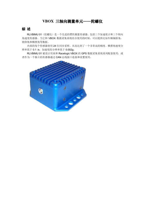
VBOX 三轴向测量单元——陀螺仪
综述
RLVBIMU 01(陀螺仪)是一个先进的惯性测量传感器,包括三个加速度计和三个转向角速度传感器。
当它和VBOX数据采集系统结合使用的时候,可以提供比如车辆倾斜角,俯仰角和横摆角等数据。
内部的每个传感器使用24位同步采样,从而达到了一个非常高的精度。
横摆角速度分辨率优于0.1°/s,加速度的分辨率优于0.002g。
RLVBIMU 01被设计用来和Racelogic VBOX的GPS数据采集系统系列配套使用,或者作为一个独立的传感器通过CAN总线接口连接和设置使用。
特点:
1.角速度范围:±150°/s
2.加速度范围:±1.7g(每轴向)
3.内部温度补偿
4.角速度分辨率:0.1°/s
5.加速度分辨率:1mg
6.CAN总线接口
规格:
输出通道数:7
通道名称:俯仰角速度,测倾角速度,横摆角速度,X方向加速度,Y方向加速度,Z方向加速度,温度
电压:直流6—18V
工作温度:-30—+70°C 尺寸:
Lemo口连接:。
自行车速度传感器工作原理
自行车速度传感器工作原理哎,朋友们,今天咱们聊聊自行车速度传感器的那些事儿。
想象一下,骑着自行车,风儿轻轻拂面,心情美得像是吃了蜜一样。
这时候,你想知道自己的速度,有没有?这就是速度传感器派上用场的地方。
说到速度传感器,其实就是个小玩意儿,但可真是个了不起的家伙,能帮你实时掌握骑行速度,让你心里有个底,骑得风生水起,或者慢悠悠地享受风景,都随心所欲。
速度传感器工作原理其实并不复杂,乍一听可能会觉得神秘兮兮的,但细一说,你就会发现其实很简单。
它的主要工作方式是通过感应轮子的转动来计算速度。
哦,轮子转得越快,你的速度就越快。
这好比你在跑步,脚步越快,跑得越远,咱们的传感器就用这种原理来测量。
说到这里,有的小伙伴可能会问,怎么测量呢?别急,来听我慢慢说。
速度传感器通常是通过一个磁性传感器和一个感应器的组合来实现的。
轮子上有个小磁铁,跟着轮子转动。
而当这个磁铁经过传感器的时候,传感器就会“嗖”一下,记录下一个信号。
这就好比你在听音乐,旋律一响,心里就跟着跳动起来。
这个信号会传到你的显示器,显示出你现在的速度,简直是一目了然,省事儿又方便。
还有个小细节,很多人可能不知道,传感器的精准度可是跟安装位置有关的。
要是安装得不对劲,数据就可能会有误差。
就像你看地图,如果标注的位置不准,走得再快也没用。
所以,安装的时候可得小心翼翼,确保它们一对儿在轮子上好好地“相处”。
你知道吗?这个小传感器不仅能告诉你速度,有时候还可以记录你的骑行距离呢。
骑了多远,速度多少,统统都能轻松搞定。
骑行的时候,看看这些数据,就像是在打游戏,心里一阵爽,成就感满满。
哎呀,谁不想成为骑行小达人呢?市面上的速度传感器种类可多着呢。
有些是无线的,简单又方便,装上后就能直接用,不用担心电线缠在一起。
而有些则是有线的,虽然有点麻烦,但价格亲民,性价比高,适合各位骑行小白们。
不过不管是什么类型,关键还是看你个人的需求,毕竟合适自己的才是最好的。
再说了,骑行不仅仅是为了速度,更是享受生活的一种方式。
速度传感器芯片
速度传感器芯片速度传感器芯片是一种可以测量物体运动速度的器件,常用于汽车、机器人、无人机等设备中。
它通过感知物体的位移和时间的关系,来计算物体的实时速度。
速度传感器芯片具有高精度、快速响应、低功耗等特点,广泛应用于各种领域。
一、速度传感器芯片的工作原理速度传感器芯片一般采用霍尔效应原理或磁阻效应原理来测量物体的运动速度。
以霍尔效应传感器为例,当物体运动时,传感器感知到物体经过时的磁场变化,通过测量磁场的变化来计算物体的速度。
具体工作原理如下:1. 传感器中有一个霍尔元件,可以感知周围的磁场。
2. 物体上附着有一个磁源,当物体运动时,磁源也会随之移动,从而改变周围的磁场。
3. 传感器感知到磁场的变化,并将其转化为电信号。
4. 根据磁场的变化情况和传感器的特性曲线,可以计算出物体的速度。
二、速度传感器芯片的应用领域速度传感器芯片广泛应用于汽车、机器人、无人机等领域,其中一些常见的应用包括:1. 汽车领域:速度传感器芯片广泛应用于汽车的车速测量、制动系统、巡航控制等方面。
通过感知车轮的转动速度,可以准确测量车辆的速度,从而实现与车速相关的控制和安全功能。
2. 机器人领域:速度传感器芯片常用于机器人的定位和导航系统中。
通过感知机器人的移动速度,可以精确计算机器人的位置和方向,从而实现自主导航和路径规划等功能。
3. 无人机领域:速度传感器芯片可以用于测量无人机的飞行速度和高度,从而实现无人机的自动控制和稳定飞行。
4. 工业自动化领域:速度传感器芯片可以用于监测工业设备的运动状态,从而实现智能化的生产和维护管理。
三、速度传感器芯片的特点和优势速度传感器芯片具有以下特点和优势:1. 高精度:速度传感器芯片具有很高的精度,可以测量物体的微小位移和速度变化。
2. 快速响应:速度传感器芯片可以实时感知物体的运动,并迅速输出测量结果。
3. 低功耗:速度传感器芯片通常具有低功耗的特点,可以有效延长设备的电池寿命。
4. 小尺寸:速度传感器芯片体积小,可以方便地嵌入各种设备中,不占用太多的空间。
- 1、下载文档前请自行甄别文档内容的完整性,平台不提供额外的编辑、内容补充、找答案等附加服务。
- 2、"仅部分预览"的文档,不可在线预览部分如存在完整性等问题,可反馈申请退款(可完整预览的文档不适用该条件!)。
- 3、如文档侵犯您的权益,请联系客服反馈,我们会尽快为您处理(人工客服工作时间:9:00-18:30)。
The VBOX Speed Sensor RangeBased on a range of high accuracy GPS engines, VBOX SpeedSensors offer the ultimate non-contact measurement solution.With 5Hz, 10Hz, 20Hz, and 100Hz GPS update rate optionsavailable, the Speed Sensor range suits a variety of budgets andrequirements. All units are also compatible with the DGPSBasestation for increased positional accuracy.The units all have the same small hardware footprint, at only 9cmlong, making mounting and transportation easy. The SpeedSensors are perfect for automotive testing, motorsport, marine,telematics, and data-logging applications. The IP66 rating meansthat each unit is water and dustproof, allowing them to be used ina variety of conditions.Data output is via CAN Bus, offering easy integration with data loggers and testing applications.Each speed sensor also features analogue and digital outputs. The analogue output can be assigned to vehicle speed, lateral acceleration, longitudinal acceleration, or lap beacon marker with user selectable scaling. The digital output can be configured as either a digital speed pulse output or a lap beacon marker.FeaturesHigh Performance GPS Receivers: 5 – 100HzCAN Bus Output of Position, Velocity, Distance, Time, Heading, Height, Vertical Velocity, Longitudinal andLateral Acceleration, Trigger to zero distance, Trigger time, Trigger speed, Radius of TurnRS232 Serial Output of NMEA, position velocity and timeUser Configurable Analogue OutputUser Configurable Digital OutputVirtual Lap Beacon OutputCompatible with DGPS BasestationRugged Deutsch ASDD autosport connectorHigh quality aluminium enclosureIP66 rated: water and dustproofWide 6.5V – 30V operating rangeLow current consumptionPackage ContentsRLVBSS XX Speed Sensor Unit. Options: VBSS05, VBSS10, VBSS20, or VBSS100RLVBACS018 GPS AntennaVBSSMAN VBOX Speed Sensor User manualCDVBSS VBOX Speed Sensor Software CDSupplied separatelyRLCAB049 VBOX Speed Sensor Interface Cable (Analogue / Digital / CAN / Serial / Power) Specifications5Hz Speed Sensor (VBSS05): GPS SpecificationsVelocity DistanceAccuracy 0.2 Km/h Accuracy 0.05% (<50cm per Km) Units Km/h or Mph Units Metres / FeetUpdate rate 5 Hz Update rate 5 HzMaximum velocity 1000 Mph Resolution 1cmMinimum velocity 0.1 Km/h Height accuracy 10 Metres 95% CEP** Resolution 0.01 Km/hLatency >160msAbsolute Positioning TimeAccuracy 5m 95% CEP** Resolution 0.01 sAccuracy w/ SBAS DGPS 1.8m 95% CEP** Accuracy 0.01 sAccuracy w/ BasestationRTCM DGPS40cm 95% CEP**Brake stop Accuracy (Trigger Activated) Update rate 5 Hz Accuracy N/AResolution 1.8 cmHeading AccelerationResolution 0.01°Accuracy 1.00%Accuracy 0.2°Maximum 4 GResolution 0.01 GUpdate rate 5 Hz Definitions** CEP = Circle of Error Probable 95% CEP (Circle Error Probable) means 95% of the time the position readings will fall within a circle of the stated diameter10Hz Speed Sensor (VBSS10): GPS SpecificationsVelocity DistanceAccuracy 0.1 Km/h Accuracy 0.05% (<50cm per Km) Units Km/h or Mph Units Metres / Feet Update rate 10 Hz Update rate 10HzMaximum velocity 1000 Mph Resolution 1cmMinimum velocity 0.1 Km/h Height accuracy 6 Metres 95% CEP** Resolution 0.01 Km/h Height accuracy with DGPS 2 Metres 95% CEP** Latency 41.5msAbsolute Positioning TimeAccuracy 3m 95% CEP** Resolution 0.01 sAccuracy with SBAS DGPS 1.8m 95% CEP** Accuracy 0.01 s40cm 95% CEP**Accuracy w/ Basestation RTCMDGPSAccuracy with Basestation DGPS20cm 95% CEP**+ GPS Upgrade (RLVBUP30)Update rate 10 Hz Brake Stop Accuracy (Trigger Activated) Resolution 1.8 cm Accuracy ±20cmHeading AccelerationResolution 0.01°Accuracy 0.50%Accuracy 0.1°Maximum 20 GResolution 0.01 GUpdate rate 10 HzDefinitions** CEP = Circle of Error Probable 95% CEP (Circle Error Probable) means 95% of the time the positionreadings will fall within a circle of the stated diameter20Hz Speed Sensor (VBSS20): GPS SpecificationsVelocity DistanceAccuracy 0.1 Km/h Accuracy 0.05% (<50cm per Km) Units Km/h or Mph Units Metres / Feet Update rate 20 Hz Update rate 20HzMaximum velocity 1000 Mph Resolution 1cmMinimum velocity 0.1 Km/h Height accuracy 6 Metres 95% CEP** Resolution 0.01 Km/h Height accuracy with DGPS 2 Metres 95% CEP** Latency 41.5 msAbsolute Positioning TimeAccuracy 3m 95% CEP** Resolution 0.01 sAccuracy with SBAS DGPS 1.8m 95% CEP** Accuracy 0.01 sAccuracy w/ Basestation RTCMDGPS40cm 95% CEP**Accuracy with Basestation DGPS+ GPS Upgrade (RLVBUP30)20cm 95% CEP**Update rate 10 Hz Brake Stop Accuracy (Trigger Activated) Resolution 1.8 cm Accuracy ±10cmHeading AccelerationResolution 0.01°Accuracy 0.50%Accuracy 0.1°Maximum 20 GResolution 0.01 GUpdate rate 20 HzDefinitions** CEP = Circle of Error Probable 95% CEP (Circle Error Probable) means 95% of the time the position readings will fall within a circle of the stated diameter100Hz Speed Sensor (VBSS100): GPS SpecificationsVelocity DistanceAccuracy 0.1 Km/h Accuracy 0.05% (<50cm per Km) Units Km/h or Mph Units Metres / Feet Update rate 100 Hz Update rate 100HzMaximum velocity 1000 Mph Resolution 1cmMinimum velocity 0.1 Km/h Height accuracy 6 Metres 95% CEP**Resolution 0.01 Km/h Height accuracy withDGPS 2 Metres 95% CEP**Latency 6.75msAbsolute Positioning TimeAccuracy 3m 95% CEP** Resolution 0.01 s Accuracy with SBAS DGPS >1.8m 95% CEP** Accuracy 0.01 s Accuracy with BasestationRTCM DGPS40cm 95% CEP**Update rate 100 Hz Brake stop Accuracy (Trigger Activated) Resolution 1.8 cm Accuracy +/- 1.8 cm Heading AccelerationResolution 0.01°Accuracy 0.50% Accuracy 0.1°Maximum 20 GResolution 0.01 GUpdate rate 100 Hz Definitions** CEP = Circle of Error Probable 95% CEP (Circle Error Probable) means 95% of the time the position readings will fall within a circle of the stated diameterOutputsCAN BusOutput Data Rate 125Kbit, 250Kbit ,500Kbit & 1Mbit selectable baud rate. Un-terminated CAN node. Data available Position, vehicle speed, heading, lateral acceleration, longitudinal acceleration, satellite count, time, radius of turn, altitude.RS232Output Data Rate 10HzData Available NMEA $GPGGA and $GPVTG messages at 115200BaudAnalogueOutput Data Rate 0 to 5v DCData Available Either Speed, Lateral Acceleration, Longitudinal Acceleration, or Lap BeaconDigital OutputOutput Data Rate Low = 0v, High = 5v, 10-1000 pulses per revolution, Max frequency 4.4KhzData Available Speed or Lap BeaconInputsPowerInput Voltage range 8v – 30v DCPower 3.7w Max (except VBSS05: 2w Max)GPS Antenna 3V Active Antenna (inc)Digital Input Cold Start Activate / Set Lap beacon PositionLED Power, Satellite Count, Event OutEnvironmental and physicalWeight Approx 250g Operating temp -30˚C to +70˚C(Except VBSS05: 190g) Storage temp -40°C to +85°CSize 90mm x 65mm x 31.85mm Connectors Deutsch ASDD Autosport RatedIP66Hardware / Software SupportHardware One Year Support ContractSoftware Lifetime Support Contract: valid for a minimum of 5 years from the date ofpurchase and limited to original purchaser. Contract includes telephone /email technical support provided by local VBOX distributor and firmware /software upgrades where applicable.。