DM-SFSR402电阻式压力传感器使用说明书
压力传感器说明书
GPD3压力传感器使用说明书煤炭科学研究总院沈阳研究院2010年5月第1版GPD3压力传感器使用说明书1、概述1.1产品特点本传感器采用精密压力敏感元件,可实现自动温度补偿,可以避免因温度变化引起的测量误差。
为尽量避免由外围元器件漂移引起的误差,所以采用很少的外围处理电路。
传感器结构简单,功能强大。
可以测量正压、负压、及压差。
1.2用途及适用范围1.2.1用于测量煤矿井下通风巷道压力。
1.2.2瓦斯抽放管道等有甲烷和煤尘爆炸危险环境的压力。
1.3型号含义1.4使用环境条件工作环境应避免淋水。
1.5工作条件1.5.1环境温度:0~40℃1.5.2相对湿度:≤98%(25℃时) 1.5.3大气压力:80~110 kPa2、安全特征2.1本传感器为矿用本质安全型。
2.2防爆标志为:Exib Ⅰ。
2、结构及工作原理图1:GY3压力传感器外型示意图G P D 3主参数:测量范围0~3.0kPa 主参数:测量范围 产品特征代号:压力差式 产品类别代号:传感器3、技术特征3.1测量范围:0~3.00kPa3.2供电电源:12~21VDC3.3电流:≤70mA3.4供电距离:1500m(电缆截面为0.43m㎡)3.5输出频率信号:200~1000Hz (负载≤600Ω)4、尺寸及重量4.1仪器外型尺寸(mm):210×130×554.2重量(kg):25、安装、调试5.1、本传感器可挂在煤矿井下需要检测压力的地方,使用时垂直悬挂。
5.2、传感器连接电缆,电缆选用四芯型矿用阻燃电缆,传感器三根引出线接法为:5.3、测量负压时,接右侧,测量取压管可选用PU管或橡胶管;当有一个取压嘴时,既可以测量正压,也可以测量负压。
注意:(1)安装取压管时,不得使传感器取压嘴的压力,超过传感器测量最大值的3倍。
(2)当有两个取压嘴时,不得用负压嘴测量正压。
5.4、电缆取压管连接无误后,给传感器送电,10秒后传感器进入稳定测量,显示所测压力的数值。
传感器使用说明书

目录0、使用注意事项 (1)1、25A电流传感器LA28-NP (2)2、50A电流传感器LT58-S7 (4)3、100A电流传感器LT108-S7 (6)4、300A电流传感器LT308-S7 (8)5、500A电流传感器LT508-S6 (10)6、1000A电流传感器LT1005-S (12)7、2000A电流传感器LF2005-S (14)0、使用注意事项(1)使用传感器之前务必至少掌握本说明书中关于传感器接线的相关知识,错误的接线会直接导致传感器的损坏。
(2)本系统配置的传感器为系统专用传感器,不得将其它类型传感器用于系统测试。
如出现损坏等情况不得不更换传感器时应更换为LEM公司的同型号传感器。
(3)系统配置的各种量程的传感器只能与系统相应量程的测量通道配合使用,不能交叉使用,否则会使测量结果错误或可能导致系统损坏。
(4)系统配置的电流传感器使用时注意电缆穿孔方向,由于系统配置的电流传感器为交直流两用传感器,正常使用时如果电缆中电流的方向与传感器上表示的方向相反一般不会影响电流幅值的测量,但是会影响交流系统与相位有关的参数测量,也会影响直流系统的电流的极性。
(5)建议传感器的测试引线和传感器壳体采用尼龙扎带固定在一起以免测试线承受拉力脱落引起电源和信号的短路。
对于端子为压接的传感器引线接线端裸漏部分不要过长,否则容易造成电源和信号的短路。
(6)对于LA28-NP,如需焊接传感器的引脚,焊接时间不能超过3秒。
安装时应采取措施避免可能出现的电路板与其它金属短路情况。
1、25A电流传感器LA28-NP2、50A电流传感器LT58-S73、100A电流传感器LT108-S74、300A电流传感器LT308-S75、500A电流传感器LT508-S66、1000A电流传感器LT1005-S7、2000A电流传感器LF2005-S。
JUMO 402050压力传感器用户指南说明书

Data Sheet 402050Page 1/7JUMO dTRANS p31Pressure transmitter for elevated media temperaturesGeneral applicationPressure transmitters are used for measuring the relative (gauge) and absolute pressures in li-quids and gases. The pressure transmitter operates on the piezo-resistive measuring principle.The pressure is converted into an electrical signal.Type 402050Technical dataReference conditions To DIN 16086 and IEC 770/5.3Ranges See order details Overload limit All ranges 3× full scale Bursting pressureAll ranges 4× full scaleParts in contact with medium Standard: stainless steel 316Ti/316LOutput0to 20mA, two-wire (output 402)Burden ≤(U B -12V)÷0.02A 4to 20mA, two-wire (output 405)Burden ≤(U B -10V)÷0.02A 4to 20mA, three-wire (output 406)Burden ≤(U B -12V)÷0.02A 0,5to 4,5V, three-wire (output 412)Burden ≥50k Ω0to 10V, three-wire (output 415)Burden ≥10k Ω1to 5V, three-wire (output 418)Burden ≥10k Ω1to 6V, three-wire (output 420)Burden ≥10k ΩBurden error <0.5% max.Zero offset ≤0.3% MSP (measuring span)Thermal hysteresis ≤±0.5% MSP (within compensated temperature range)Ambient temperature error Within range 0to 100°C (compensated temperature range)Zero≤0.02%/K typical, ≤0.04%/K max.Measuring span≤0.02%/K typical, ≤0.04%/K max.Deviation from characteristic ≤0.5% MSP (limit point setting)For basic type extension 023≤0.2% MSP (limit point setting)Hysteresis ≤0.1% MSPData Sheet 402050Page 2/7Repeatability≤0.05% MSPResponse timeCurrent output0to20mA, two-wire (output 402)≤3msec max.4to20mA, two-wire (output 405)≤3msec max.4to20mA, three-wire (output 406)≤3msec max.Voltage output0,5to4,5V, three-wire (output 412)≤10msec max.0to10V, three-wire (output 415)≤10msec max.1to5V, three-wire (output 418)≤10msec max.1to6V, three-wire (output 420)≤10msec max.Stability over 1 year≤0.5% MSPVoltage supply a0to20mA, two-wire (output 402)DC11,5to30V4to20mA, two-wire (output 405)DC10to30V4to20mA, three-wire (output 406)DC11,5to30V0,5to4,5V, three-wire (output 412)DC5V0to10V, three-wire (output 415)DC11,5to30V1to5V, three-wire (output 418)DC10to30V1to6V, three-wire (output 420)DC10to30VMax. current drawn Approx. 25mAVoltage supply influence≤0.02%/V, nominal voltage supply DC24Vratiometric with voltage supply DC5V (±0.5V)-20to+125︒CPermissible ambient temperature(max. housing temperature)Storage temperature-40to+125︒CPermissible temperature of medium-30to+200°CElectromagnet compatibility EN 61326Interference emission Class BInterference immunity Industrial requirementsMechanical shock b100g/1msecMechanical vibration c Max. 20g at 15to2000HzProtection type dTerminal box (electrical connection 12)IP67Round plug M12×1IP67(electrical connection 36)Cable socket (electrical connection 61)IP65 (connecting cable diameter min. 5mm, max. 7mm)Housing Stainless steel, mat. ref. 1.4301Polycarbonate GFPressure connection See order details; other connections on requestElectrical connection See order detailsTerminal box (electrical connection 12)4-pole, PVC cable, length 2m, other length on request4-poleRound plug M12×1(electrical connection 36)Cable socket (electrical connection 61)To DIN EN 175301-803, conductor cross-section upt ot max. 1.5mm2Nominal position AnyWeight200ga Ripple: The voltage spikes must not go above or below the values specified for the supply.b DIN IEC 68-2-27c DIN IEC 68-2-6d EN 60529Data Sheet 402050Page 3/7Connection diagramThe connection diagram in the data sheet provides preliminary information about the connection options. For the electrical connection only use the installation instructions or the operating manual. The knowledge and the correct technical execution of the safety information/instructions contained in these documents are mandatory for installation, electrical connection, startup, and for safety during operation.ConnectionTerminal assignment 123661Fixed cableRound plug M12×1Cable socket Voltage supply DC 10to 30V DC 11,5to 30V DC 5V White Grey1+3- 1 L+2 L-Output 1to 6V 0to 10V 0,5to 4,5VGrey Yellow 3-4+ 2 -3 +Output 4to 20mA, two-wireWhite Grey 1+3- 1 +2 -Proportional current 4to 20mA in voltage supplyOutput 0(4)to 20mA, three-wireGrey Yellow3-4+2 -3 +Protection conductor Screen Black2Caution:Earth device(pressure connection and/oror screen)!Data Sheet 402050Page 4/7DimensionsElectrical connection Process conntection, front-flushBO-ringBO-ringData Sheet 402050Page 5/7Process connection DNØD1ØD2ØD3ØD4L1L2ProcessconnectionDNDIN 32676DN(Zoll)Nominal SizeISO 2852ØD1ØD26032036.530RD44×1/6541321612201227.534 604254435RD52×1/663151512.7605325041RD58×1/67017.2606405648RD65×1/67821.36075068.561RD78×1/6921622613251“2543.550.532 1.5“33.74038616502“4056.56451see data sheet 409711Data Sheet 402050Page 6/7Order details(1)Basic type402050/000JUMO dTRANS p31 – Pressure transmitter for elevated media temperatures402050/023JUMO dTRANS p31 – Pressure transmitter for elevated media temperatures, reduced deviation from characteristic a 402050/999JUMO dTRANS p31 – Pressure transmitter for elevated media temperatures, special version(2)Input4540to1bar relative pressure4550to1,6bar relative pressure4560to2,5bar relative pressure4570to4bar relative pressure4580to6bar relative pressure4590to10bar relative pressure4600to16bar relative pressure4610to25bar relative pressure4620to40bar relative pressure4630to60bar relative pressure478-1to0bar relative pressure479-1to+0,6bar relative pressure480-1to+1,5bar relative pressure481-1to+3bar relative pressure482-1to+5bar relative pressure483-1to+9bar relative pressure484-1to+15bar relative pressure485-1to+24bar relative pressure4880to1bar absolute pressure4890to1,6bar absolute pressure4900to2,5bar absolute pressure4910to4 bar absolute pressure4920to6bar absolute pressure4930to10bar absolute pressure4940to16bar absolute pressure4950to25bar absolute pressure998Sondermessbereich absolute pressure999Sondermessbereich relative pressure(3)Output4020to20mA, three-wire4054to20mA, two-wire4064to20mA, three-wire4120,5to4,5V, three-wire4150to10V, three-wire4181to5V, three-wire4201to6V, three-wire(4)Process connection550Aseptic to DIN 11864-1A, DN20551Aseptic to DIN 11864-1A, DN25552Aseptic to DIN 11864-1A, DN32553Aseptic to DIN 11864-1A, DN40554Aseptic to DIN 11864-1A, DN50570G11/2 front-flush, DIN EN ISO 228-1571G3/4 front-flush, DIN EN ISO 228-1575G3/4 front-flush with double sealData Sheet 402050Page 7/7576G1 with double seal584SMS, DN1585SMS, DN11/2586SMS, DN2603Taper socket with grooved union nut DN20, to DIN 11851 (dairy pipe fitting)604Taper socket with grooved union nut DN25, to DIN 11851 (dairy pipe fitting)605Taper socket with grooved union nut DN32, to DIN 11851 (dairy pipe fitting)606Taper socket with grooved union nut DN40, to DIN 11851 (dairy pipe fitting)607Taper socket with grooved union nut DN50, to DIN 11851 (dairy pipe fitting)612Clamping socket (clamp) DN10, DN15, DN20b to DIN 32676613Clamping socket (clamp) DN25, DN40b to DIN 32676616Clamping socket (clamp) DN50 (2“)b to DIN 32676619Clamping socket (clamp) DN15 (3/4“)b to DIN 32676623Small flange DN25, to DIN 28403652Tank connection with grooved union nut DN25661Clamping flange (DRD), Ø65mm684VARIVENT® connection, DN15/10685VARIVENT® connection, DN32/25686VARIVENT® connection, DN50/40997JUMO-PEKA with EHEDG certification c(5)Process connection material20CrNi (stainless steel)(6)Electrical connection12Terminal box, screened, 2m (other length on request)36Round plug M12×161Cable socket DIN EN 175301-803, form A(7)Extra codes000None452Parts in contact with the medium are electropolished, surface roughness Ra 0.8µm631Improved moisture and vibration protectiona A reduced deviation from characteristic is not available for ± ranges; it is available only in conjunction with 4to20mA, two-wire (output 405).b These process connections are only suitable with measuring spans up to 25bar.c Suitable process connection adapter, see data sheet 409711(1)(2)(3)(4)(5)(6)(7) Order code-----/Order example402050/000-459-405-571-20-61/000AccessoriesArticle Part no.Cable box (straight) with control cable, screen, 4-pole, 5m PVC cable, pressure compensation00512341。
气压传感器(大气压传感器)使用说明书

气压传感器(大气压传感器)使用说明书一、概述气压传感器采用带不锈钢隔离膜的扩散硅压阻式压力传感器作为信号测量元件,信号处理电路位于不锈钢壳体内,传感器信号经过经过专业信号调理电路转换成标准4-20mA 电流或RS485信号输出,。
气压传感器DATA-52系列经过了长期老化及稳定性考核等工艺,性能稳定可靠。
气压传感器广泛地应用于石油、化工、冶金、电力等工业过程现场测量和控制。
防护等级:IP68。
型号意义:示例说明:DATA-5202(100kPa)表示为平升公司生产的4~20mA ,精度为0.5%,量程为100kPa 的压力变送器。
二、外形结构(单位:mm ):供货产品接口螺纹: M20×1.5 □ G1/2 □三、工作原理气压传感器是以单晶硅为基体,采用先进的离子注入工艺和微机械加工工艺,制成了具有惠斯顿电桥和精密力学结构的硅敏感元件。
被测压力通过压力接口作用在硅敏感元件上,实现了所加压力与输出信号的线性转换,经激光修调的厚膜电阻网络补偿了敏感元件的温度性能。
四、性能指标 型号:DATA-52系列通讯类型:1—串口; 2—4~20mA;精 度:0—0.5%; 1—0.1%;DATA-5 2 ××(×kPa 、MPa 等)量程:0—×,单位:kPa 、MPa (一般在标牌中标注) 采集类型:压力;唐山平升电子生产的变送器系列产品测量介质:液体或气体(对不锈钢壳体无腐蚀)量程:0-10MPa输出信号:4-20mA;RS485供电电源:12/24V DC精度等级:0.1%FS;0.5%FS环境温度:-10℃~80℃存储温度:-40℃~85℃过载能力:150%FS稳定性能:±0.05%FS/年; ±0.1%FS/年零点温度系数:±0.01%FS/℃满度温度系数:±0.02%FS/℃防护等级:IP68结构材料:外壳:不锈钢1Cr18Ni9Ti 密封圈:氟橡胶传感器外壳:不锈钢1Cr18Ni9Ti 膜片:不锈钢316L电缆:φ7.2mm聚氨酯专用电缆(配套2米,超出部分按长度加价)五、注意事项1.当收到产品时请检查包装是否完好,并核对变送器型号与规格是否与您选购的产品相符。
KONGSBERG GT402 海洋应用压力传感器说明书

The KONGSBERG GT402 is a type approved pressure transmitter, specially designed for maritime applica-tions, like inert gas pressure, pump and line pressure measurements, and for level measurements in tanks. The transmitter is made in stainless steel AISI316L and suitable for wet installations rated IP67. Available as an absolute, sealed gauge or a gauge type, with pressure ranges from 0.25 to 400 Bar.PRESSURE TRANSMITTERPrinciple of operationThe pressure sensing element is a dry, robust ceramic sensor element, with an internal strain gauge Wheatstone-bridge. For each sensor, the characteristics of the strain gauge is digitized and stored at known applied pressure and temperature and kept in sensor memory for the sensor’s lifetime. This digital calibration enables a possibility to linearize and temperature compensate each transmitter uniquely, which again ensures high accuracy and temperature stability of each measurement.The 96 % alumina membrane is resistant to most chemicals, thus the process medium is in direct contact with the measuring membrane, and there is no need for de-coupling in the form of a filling liquid and second membrane. A filling liquid and a second membrane can be a source of errors. This is why dry capsule sensors have superior specifications compared to wet capsule versions.InstallationThe transmitter consists of a sensing element together with a signal converter unit encapsulated in a body made of stainless steel, AISI 316L. For seawater applications a transmitter with front adapter in Titanium is available.Process connection is ISO228-G1/2A threads, male connector.The electrical connection is by a cable gland on the connection box. Minimum requirement is 2 x 0.5 mm 2 twisted pair cable with Cu-screen. The Cu-screen shall be grounded in the cable gland on the transmitter. On the monitoring side, the screen shall be grounded as near to the input channel in the monitoring cabinet/system as possible (see Figure 1).Power supply to the transmitter is 24 VDC nominal, but thetransmitter will tolerate a variation from 12 VDC to 32 VDC from the power source.When used in hazardous areas as Intrinsic Safe apparatus, the power supply is restricted to 28 VDC. The allowable load is determined by the minimum power supply.The KONGSBERG DZ-120 Transmitter Barrier matches the GT402 pressure transmitter perfectly, and allows the transmit-ter to be used in hazardous areas (for connection details, see Figure 2).Kongsberg Maritime can deliver detailed installation instructions and necessary installation material for various applications.DRAWINGS AND INSTALLATIONFigure 1: Electrical and mechanical installation of GT402Figure 2: Connection diagram for Ex-area installationsORDER CODEThe system must be depressurized before assembly of the pressure transmitters.Compliance with the Essential Health and Safety Requirements has been assured by compliance with:CENELEC EN 60079-0 : 2012 and CENELEC EN 60079-11 : 2012• The stated input values Ui, Ii and Pi are to be regarded as individual maximum values. It is a precondition that the diode safety barrier in the supply circuit has a linear resistive output characteristic.• When installing titanium sensors, special caution must be taken to avoid ignition hazard due to impact or friction.For details about safe installation and various solutions for different applications, see the GT400 Series Pressure Sensor Applica -tions Guidelines369048.SPECIAL CONDITIONS FOR SAFE USEMeasuring range: 0.25 to 400 barAccuracy*: See order code Temperature drift: See order codeLong term drift: < 0.3 % /year (% of nom. range)Output signal: 4 to 20 mA / HART Output current:3.8 mA < Io < 21.6 mA Output current at fault: Io ≤ 3.6 mAPower supply: 24 VDC (12 to 32 VDC depending on load resistance)Load resistance: 0 to 1150 ohm dependingon power supplyEx classification: Ex certification: NEMKO 02ATEX119X IECEx NEM 12.0008XEnvironmental standards: IACS E10 CISPR 22Operating temperature: - 45 °C to + 85 °C Storage temperature: - 50 °C to + 100 °C Materials Body: AISI 316 / Titanium gr.2Membrane: 96 % alumina ceramics Gasket:See order keyProtection grade: IP 56 (gauge transmitter) IP 66/67 (abs. transmitter)Weight: 0.4 kgCable gland:M20, M20+ or M25Safety dataMax. input voltage: Ui = 28 VDC Max. input power: Pi = 0.85 W Max. input current: Ii = 150 mA Max. internal capacitance: Ci = 30 nF Max. internal inductance: Li = NegligibleType approvals: MR (EU mutual recognition), NK, CCS, ABS * Including non-linearity, hysteresis and repeatibility at 22 ˚C. ** FRO = Full Range OutputSpecifications subject to change without any further notice.TECHNICAL SPECIFICATIONSFEATURES• Accuracy 0.25 % of FRO**• Temperature drift < 0.005 % of FRO**/˚C • Pressure ranges from 0.25 to 400 Bar • HART compatible• Membrane made of 96 % alumina ceramics • Body of AISI 316 L or titanium •Rugged constructionP -G T 402/C E R e v . TE-mailsales:*********************.comE-mailsupport:************************Figure 3: Dimensional sketch of GT402。
视神sunx_压力传感器_DP2_使用说明书
产品。
请仔细、完整地阅读此使用说明书以便正确、合理地使用此产品。
请把此使用说明书放在随手可得之处以便快速查找。
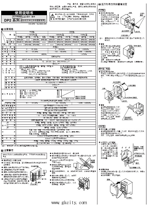
2注意事项DP2系列设计为使用非腐蚀性气体。
不可用于液体或腐蚀性气体。
ⅷ请在额定压力范围内使用。
ⅷ切勿使压力超过耐压值。
否则隔膜会受到损伤并且无法进行正常操作。
ⅷⅷ注意错误接线可能损坏传感器。
ⅷ请确认电源电压在额定范围内变化。
ⅷ如果电源由一商用开关调节器提供,请确保电源机架接地端子(F.G.)ⅷ如果在该产品附近使用产生噪音的设备(开关调节器,转换发动机等)请将设备机架接地端子(F.G.)ⅷ电源接通后的短时间0.5s内,请勿使用。
ⅷ能会由于感应引起失灵。
ⅷ0.3mm2不超过100m。
ⅷ避免在水蒸气和灰尘过多的地方使用标准型、扁平型和轻型传感器。
ⅷ请勿将传感器与水、油、油脂或有机溶液,如稀释剂等直接接触。
ⅷ隔膜并影响正常操作。
ⅷⅷ勉强弯曲,硬拉等。
1(注1):带有后缀‘-P’ 的北美标准型号是PNP输出型。
4标准型传感器安装ⅷ需要使用传感器安装支架MS-DPX 和MS-DPX-4(另售)用传感器安装支架等安装传感器时,紧固扭矩应在1.2N ⅐m 以下。
ⅷ同时也配有面板安装支架MS-DPX-2(另售)和正面防护罩DPX-04(另售)。
5I/O 电路图NPN输出型符号... D: 反向电源极性保护二极管Z D1, Z D2, Z D3: 电涌吸收齐纳二极管Tr 1, Tr 2: NPN 输出晶体管(注1):模拟电压输出不装备短路保护电路。
不可直接连接到电源或容量负荷上。
当使用模拟电压输出时,请注意连接具有适当输入阻抗的外部设备。
另外,当使用延长电缆时,由于要考虑电缆电阻,电压会下降。
PNP输出型符号... D: 反向电源极性保护二极管Z D1, Z D2, Z D3: 电涌吸收齐纳二极管Tr 1, Tr 2: PNP 输出晶体管(注1):模拟电压输出不装备短路保护电路。
不可直接连接到电源或容量负荷上。
智能传感器仪表说明书
四、主要技术参数三、常规型号说明二、仪表型号2、测量信号参数表:2.配线注意事项:1)热电偶输入的场合,请使用规定的补偿导线;如果被测量设备为金属加热物请使用带绝缘的热电偶。
2)热电阻输入的场合,请使用导线电阻较小的,且(3线式)无电阻差的线材,但总长度应在5m 内。
3)为了避免噪声干扰的影响,请将输入信号远离仪器电源线、动力电源线、负载线进行配线。
4)为了减小动力电源线以及大负载电源线对本产品的影响,请在容易受到影响的场合,建议使用噪声滤波器。
如果使用噪声滤波器,请务必将其安装在接地的盘面等上,并使噪声滤波器输出侧与电源端子间的配线最短;不要在噪声滤波器输出侧的配线上安装保险丝、开关等,否则会降低滤波器的效果。
5)本产品在投入电源时到有输出时间约为5秒。
如果有联锁动作的电路等信号使用的场合,请使用延时继电器。
6)变送输出线请尽量使用带屏蔽层的双绞线;确保信号可靠稳定。
7)远距离RS485通讯线请使用带屏蔽层的双绞线,并将屏蔽层在主机侧接地处理;确保通讯可靠稳定。
8)本产品没有保险丝;需要的场合请按额定电压250V,额定电流1A 配置,保险丝种类:延时保险丝。
9)请使用适合的螺丝力及适合的压接端子端子螺丝尺寸:M3X8(带6.8X6.8方座)推荐拧紧力矩:0.4N.m合适线材:0.25~1.65mm 的单线或多芯软线10)请不要将压接端子或裸露线部分与相邻的端子接触。
智能传感器仪表说明书产品特点:●上排红色大数码管显示实时、最大、最小、保持值,下排绿色数码管显示测量单位或报警值。
●最多支持3路报警输出。
●支持多种线性信号输入或多种温度传感器信号。
●变送电流输出,可实现变送量程的变换及校准功能。
●可实现RS485通讯,采用标准Modbus-RTU 协议。
●宽电源电压范围100~240V AC/DC。
●隔离DC24V 馈电输出(30mA)。
●峰值保持功能,方便记录测量数据的最大值、最小值。
●操作简便,经济实用。
DMR说明书
1.概述.... ................... ............................. (3)2.主要技术指标............................................ .. (3)3. 仪表显示及操作........ ........................................ (4)3.1 单通道曲线显示及操.................................. . (4)3.2 多通道曲线显示及操作.................. (4)3.3棒图画面显示及操作.. .... .. (5)3.4大字/数显画面..... (6)3.5流量累积显示数据存盘.................. . (7)3.6仪表设置显示画面及操作. (8)4.仪表参数设置... ................... .. (11)4.1 参数设置方法 .. (11)4.2 仪表公共参数说明..... . (11)4.3通道参数说明...... . .. (12)5. 仪表标定. ............... . .............................. (16)5.1 标定准备工作....... . (16)5.2 标定方法..... ..... ........ (16)5.3 热电阻通道零点及增益调校方法 (17)5.4 电流输出通道增益标定.................... .. (18)6.仪表安装与接线.. (19)6.1 仪表安装. .. (19)6.2 各种输入信号接线及设置 (20)6.3 电流输出通道接线及设置 (20)6. 4 输入通道开关设置. (21)7.流量累积算法. (22)7.1 累积算法.. (22)7.2 差压. 温度及压力输入通道设定 (24)7.3 全补偿流量积算参数设置 (25)7.4 全补偿流量积算参数设置举例 (26)8.仪表通讯.. . ...... (27)8.1 通讯方式 (27)8.2 通讯接线 (27)8.3 通讯数据 (28)9.仪表通道工位文字设置 (29)9.1工位文字软件安装方法 (29)9.2 工位文字编辑... .... . (29)9.3工位文字文本文件格式转换 (30)9.4 工位文字转存记录仪 (30)10.附加功能.................... .. (31)10.1 仪表两线制供电. (31)10.2 数据在线打印 (31)11. 仪表使用环境及维护 .. ... .. (32)11.1 仪表使用环境及注意事项............ . (32)11.2 常见问题及处理方法 (32)附录一.DMR输入信号一览表. ........ . (34)附录二.DMR信号单位一览表........ (34)附录三.通道模式开关定义........ . (34)附录四 DMR100 仪表端子图........ . (35)附录五 DMR180仪表端子图........ . (35)1. 概述DMR系列无纸记录仪,采用了宽视角、宽温、高亮度大屏幕液晶显示记录曲线,大容量FLASH RAM实时存储记录数据和全智能嵌入式高可靠磁盘数据备份三项最新技术。
系列压力传感器操作手册
1. 设定参考输出状态:在量测模式下按
键超过四秒,屏幕出现
后放开,进入进阶设定模式。按
色的参考项目(详见进阶设定模式方块图)。按
键选择所要的参考项目。
键四下可看见设定颜
2. 颜色切换:在量测模式下按
键超过二秒,切入简易设定模式。按
键四下可看见设定显示颜色切换功能(详见简易设定模式
方块图)。按
键选择所要的显示颜色
注:「输出一 and 输出二」是当输出一以及输出二皆为 ON 时,才为 ON,否则皆为 OFF;「输出一 or 输出二」是当输出一以及输出二
皆为 OFF 时,才为 OFF,否则皆为 ON。
Code 代码
DPB 提供显示代码,供用户对照设定。在量测模式下按
键超过四秒,屏幕出现
下可看见显示代码(详见进阶设定模式方块图) 代码相关意义如下表:
键找到
,
设定所需的单位。
2. 输出状态:DPB 可设定两种输出状态,N.O.(常开)和 N.C.(常闭)。用户可在简易设定模式下,按 出一、二的输出状态。
键找到
,设定输
3. 反应时间设定:当压力达到输出状态时的反应时间。如设定为 50 代表当压力达到输出状态时必须维持 50ms,输出才会动作。用户可
6. 设定功能键 7. 向下调整键 8. 电源和输出信号端子 9. 压力输入气孔
DPB 1 2 量测压力范围 3 输出型式 4 压力气孔型式
台达 DPB 系列压力传感器 01: -100kPa ~ 100kPa, 10: -100kPa ~ 1,000kPa N: NPN output;P: PNP output P:外孔 PT 1/8、内孔 M5;N:外孔 NPT 1/8、内孔 M5;G:外孔 G 1/8、内孔 M5
杰瑞斯压力传感器产品说明书
U Automobile Industry
Power supply (+)
Switch 2 output (+)
Switch 1 output (+)
To Order
SINGLE SWITCHING OUTPUT MODEL NO. ADJUSTABLE RANGE
DUAL SWITCHING OUTPUTS MODEL NO. ADJUSTABLE RANGE PSW14B-AN 0 to 145 psig (0 to 10 bar) PSW14B-BN 0 to 1450 psig (0 to 100 bar) PSW14B-CN 0 to 5800 psig (0 to 400 bar) PSW14B-DN 0 to 8700 psig (0 to 600 bar)
Electronic Pressure Switch
Single or Dual with Stainless Steel Diaphragm
0-145 psi to 0-8700 psi
PRESSURE SWITCHES
PSW14 Series
PSW14A-AN, shown actual size.
Specifications
PSW14A-DN 0 to 8700 psig (0 to 600 bar)
Sensor Element: Piezoresistive silicon or ceramic measuring cell
Wetted Parts: Steel, pass., AI2O3 Electronics Housing: Polyamide Seals: FKM
- 1、下载文档前请自行甄别文档内容的完整性,平台不提供额外的编辑、内容补充、找答案等附加服务。
- 2、"仅部分预览"的文档,不可在线预览部分如存在完整性等问题,可反馈申请退款(可完整预览的文档不适用该条件!)。
- 3、如文档侵犯您的权益,请联系客服反馈,我们会尽快为您处理(人工客服工作时间:9:00-18:30)。
电阻式压力传感器用户使用说明书
V1.0
深圳市中科鸥鹏智能科技有限公司
2010年11月
目录
1.简介 (3)
2.技术参数 (3)
3.注意事项 (4)
4.安装方法及软件 (5)
1.简介
FSR402是著名Interlink Electronics 公司生产的一款重量轻,体积小,感测精度高,超薄型电阻式压力传感器。
这款压力传感器是将施加在FSR传感器薄膜区域的压力转换成电阻值的变化,从而获得压力信息。
压力越大,电阻越低。
其允许用在压力100g-10kg的场合。
可用于机械夹持器末端感测有无夹持物品,仿生机器人足下地面感测,哺乳类动物咬力测试生物实验,应用范围及其广泛。
但是由于压力检测不是非常精确,因此不建议使用需要精确检测压力的场合。
2.技术参数
●工作电压:5VDC@165mA
●传感器感应面积:直径12.7mm
●传感器类型:被动式可变电阻
●压力感应范围:100g ~ 10 kg
●使用寿命:>100万次挤压
图1
压力感应电阻是弯曲压力传感器的一种,简称FSR,FSR是一种随着有效表面上压力增大而输出阻值减小的高分子薄膜,FSR并不是测压元件或形变测量仪,尽管他们有着相似的性能。
而且这类压力感测电阻不适用于精密测量,但是FSR却是一款灵敏度较高的传感器。
图2
图3
这是它的性能曲线
3.注意事项
FSR的厚度为0.2mm—1.25mm,这款传感器的厚度为0.3mm。
压力敏感范围是从100g 到10kg.。
声压灵敏度是从0.1kg/cm²到10 kg/cm²。
在安装时有几个注意事项:
●要尽量选择稳固,光滑且平坦的安装表面;
●当你的安装表面是曲面时,你安装FSR时势必会弯曲它,这样一来FSR就会受力,就会
一定程度上影响到FSR的精确度,所以要注意尽量不要将FSR的有效表面安装在曲面上(注:是圆形有效表面不可弯曲,而长尾部可以弯曲);
●要保持接触表面的清洁;
●受力不要超过它的额定值;
●尽量不要将它焊接到万用板或没有属于它的特定封装的电路板上,以免尾部会受热变
形;
●若用导线将其接入电路,注意最好要用热缩管将尾部两部分隔开。
4.安装方法及软件
将FSR接入电路,有以下两种接法:
图4
用AVR单片机读出它的模拟值,模拟值范围方案一是0~1024,方案二是1024~0。
这里我做了个小实验,使用的是方案一的接法,如图:
在11PWM接口连接了一个LED,并将FSR读出的模拟值赋给LED,这样通过LED的亮度我们就可以看出读出模拟值和压力的大小了。
下面是程序代码:
#include<avr/io.h>
#include<avr/delay.h>
#include<avr/signal.h>
#include<avr/interrupt.h> //中断函数头文件
//常量声明
#define BAUD 9600 //波特率设置值
//全局变量声明
unsigned int ADData; //AD转换获得的数据
//函数声明
void Port_Init(void); //端口初始化配置
void Usart_Init(void); //USART寄存器设置
void AD_Init(void); //AD初始化
void Usart_PutChar(unsigned char cTXData); //字节发送函数
void Usart_PutString(unsigned char *pcString); // 字符串发送数据
unsigned int AD_GetData(void); //AD转换函数
//端口状态初始化设置函数
void Port_Init()
{
DDRC=0x00;
PORTC = 0X00;//ADC通道设置为输入口,高阻态
}
//USART寄存器配置函数
void Usart_Init()
{
UCSRA = 0X00;
UCSRC |= (1<<URSEL) | (1 << UCSZ1) | (1 << UCSZ0); //异步,数据格式8,N,1 //UCSRC寄存器与UBRRH寄存器共用相同的I/O地址,写 UCSRC 时, URSEL 应设置为 1。
UBRRL = (F_CPU / BAUD / 16 - 1) % 256; //波特率设置
UBRRH = (F_CPU / BAUD / 16 - 1) / 256;
UCSRB |= (1 << RXCIE) | (1 << RXEN) | (1 << TXEN); //发送使能
}
//字节发送函数
void Usart_PutChar(unsigned char cTXData)
{
while( !(UCSRA & (1 << UDRE)) ); //只有数据寄存器为空时才能发送数据
UDR = cTXData; //发送数据送USART I/O数据寄存器-UDR
}
//接收中断函数完成
SIGNAL(SIG_UART_RECV)
{
unsigned char Rev;
Rev = UDR; //从USART I/O数据寄存器-UDR中读出数据
Usart_PutChar(Rev); //将接收到的数据发送
}
void Usart_PutString(unsigned char *pcString)
{
while (*pcString)
{
Usart_PutChar(*pcString++);
}
Usart_PutChar(0x0D);
Usart_PutChar(0x0A); //结尾发送回车换行
}
//AD转换初始化函数
void AD_Init()
{
ADMUX |= (1 << REFS0);//|(1<<MUX2)|(1<<MUX1)|(1<<MUX0); //ADC参考电压为AVcc,ADC结果右对齐,选择通道ADC0
ADCSRA |= (1 << ADEN) | (1 << ADPS2) | (1 << ADPS1); //使能AD转换,ADC时钟64分频
}
//AD转换函数
unsigned int AD_GetData()
{
ADCSRA |= (1 << ADSC); //开始AD转换
while(!(ADCSRA & (1 << ADIF))); //等待转换完成
ADCSRA |= (1 << ADIF); //清零ADC中断标志位
return ADC; //返回ADC值
}
int main(void)
{
Port_Init();
Usart_Init();
AD_Init();
sei(); //使能全局中断
while(1)
{
ADData = (int)AD_GetData(); //将获得的AD值转换为电压值
Usart_PutString("\r\nAnalog reading = ");
Usart_PutChar(ADData / 1000 + 0x30);
Usart_PutChar(ADData % 1000 / 100 + 0x30);
Usart_PutChar(ADData % 100 / 10 + 0x30);
Usart_PutChar(ADData % 10 + 0x30);
Usart_PutChar(0x0d);
// Usart_PutChar(0x0a); // AD值发送结束,回车换行
_delay_ms(90);
_delay_ms(90);
_delay_ms(90);
}
}
可以看到当我用力按FSR有效表面时,LED在发光,而且LED会随着我用力的大小而改变亮度。