NOx 传感器
氧传感器原理
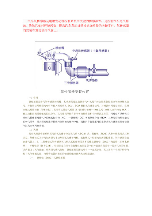
汽车氧传感器是电喷发动机控制系统中关键的传感部件,是控制汽车尾气排放、降低汽车对环境污染、提高汽车发动机燃油燃烧质量的关键零件。
氧传感器均安装在发动机排气管上。
氧传感器安装位置一:作用氧传感器是排气氧传感器的简称,其功用是通过监测排气中氧离子的含量来获得混合气的空燃比信号,并将该信号转变为电信号输入到发动机ECU。
ECU根据氧传感器信号,对喷油时间进行修正,实现空燃比反馈控制(闭环控制),从而将过量空气系数(λ)控制在0.98~1.02之间(空燃比A/F约为14.7),使发动机得到最佳浓度的混合气,从而达到降低有害气体的排放量和节约燃油之目的。
同时也可以确保三效催化转化器对排气中的碳氢化合物(HC)、一氧化碳(CO)和氮氧化合物(NOX)三种污染物都有最大的转化效率,最大程度地进行排放污染物的转化和净化。
现代汽车普遍采用的宽带式氧传感器还具有检查气缸失火和判缸功能。
二:类型发动机燃油喷射系统采用的氧传感器分为氧化锆(ZrO2)式、氧化钛(TiO2)式和六线宽带式三种类型。
氧化锆式又分为加热型与非加热型氧传感器两种,氧化钛式一般都为加热型传感器。
氧传感器安装在排气管上。
3.二氧化锆式氧传感器氧化锆式氧传感器的基本元件是氧化锆(ZrO2)陶瓷管(固体电解质),亦称锆管(图7-33a)。
锆管固定在带有安装螺纹的固定套中内外表面均覆盖着一层多孔性的铂膜,其内表面与大气接触,外表面与废气接触。
氧传感器的接线端有一个金属护套,其上开有一个用于锆管内腔与大气相通的孔,电线将锆管内表面的铂极经绝缘套从此接线端引出。
(一)氧化锆(ZrO2)式氧传感器结构图1.保护套管2.内表面铂电极层3.氧化锆陶瓷体4.外表面铂电极层5.多孔氧化铝保护层6.线束接头原理图锆管的陶瓷体是多孔的,渗入其中的氧气,在温度较高时发生电离。
由于锆管内、外侧氧含量不一致,存在浓差,因而氧离子从大气侧向排气一侧扩散,从而使锆管成为一个微电池,在两铂极间产生电压(图7-33b)。
氧传感器的检测
氧传感器的检测1、结构和工作原理在使用三效催化转化器降低排放污染的发动机上,氧传感器是必不可少的。
三效催化转化器安装在排气管的中段,它能净化排气中CO、HC和NO x三种主要的有害成分,但只在混合气的空燃比处于接近理论空燃比的一个窄小范围内,三效催化转化器才能有效地起到净化作用。
故在排气管中插入氧传感器,借检测废气中的氧浓度测定空燃比。
并将其转换成电压信号或电阻信号,反馈给ECU。
ECU控制空燃比收敛于理论值。
目前使用的氧传感器有氧化锆式和氧化钛式两种,其中应用最多的是氧化锆式氧传感器。
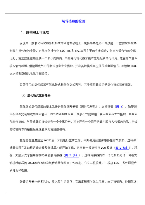
(1)氧化锆式氧传感器氧化锆式氧传感器的基本元件是氧化锆陶瓷管(固体电解质),亦称锆管(图1)。
锆管固定在带有安装螺纹的固定套中,内外表面均覆盖着一层多孔性的铅膜,其内表面与大气接触,外表面与废气接触。
氧传感器的接线端有一个金属护套,其上开有一个用于锆管内腔与大气相通的孔;电线将锆管内表面铂极经绝缘套从此接线端引出。
氧化锆在温度超过300℃后,才能进行正常工作。
早期使用的氧传感器靠排气加热,这种传感器必须在发动机起动运转数分钟后才能开始工作,它只有一根接线与ECU相连(图2(a))。
现在,大部分汽车使用带加热器的氧传感器(图2(b)),这种传感器内有一个电加热元件,可在发动机起动后的20-30s内迅速将氧传感器加热至工作温度。
它有三根接线,一根接ECU,另外两根分别接地和电源。
锆管的陶瓷体是多孔的,渗入其中的氧气,在温度较高时发生电离。
由于锆管内、外侧氧含量不一致,存在浓差,因而氧离子从大气侧向排气一侧扩散,从而使锆管成为一个微电池,在两铂极间产生电压(图3)。
当混合气的实际空燃比小于理论空燃比,即发动机以较浓的混合气运转时,排气中氧含量少,但CO、HC、H2等较多。
这些气体在锆管外表面的铅催化作用下与氧发生反应,将耗尽排气中残余的氧,使锆管外表面氧气浓度变为零,这就使得锆管内、外侧氧浓差加大,两铅极间电压陡增。
盛思锐 用于SGP40和SGP41的评估套件 VOC和NOx 室内空气质量传感器 应用说明书

Technical Description SEK-SVM4xEvaluation Kit for SGP40 and SGP41 – Indoor Air Quality Sensor for VOC and NO x MeasurementsSensor module equipped with SGP41 and SHT40 On-board microcontroller for signal processing I 2C and UART interface with digital output signals USB-UART cable, jumper wire cable set Power supply 3.0–5.5 VPlug-and-play for fast evaluation and prototypingTable of Contents1 General Description (3)2 Specifications (4)3 Sensor Output Signal Description (7)1General DescriptionSpecifications can be found in the corresponding datasheets of both components SGP41 and SHT40. The SVM41 as part of the evaluation kit SEK-SVM4x serves as reference design for integrating SGP41, SHT40, and Sensirion’s Gas Index Algorithm to obtain the VOC and NO x Index signals as processed by the on-board microcontroller. It supports all features of both components and automatically takes care of humidity compensation of the SGP41 raw signal as well as of temperature offset compensation of the SHT40 sensor. Figure 1 visualizes how the signal processing is performed on the SVM41. ArrayFigure 1 Schematic of the signal processing and interface on SVM41.2 Specifications2.1 Electrical SpecificationsTable 1 lists electrical specifications of the SVM41. The SVM41 supports both I 2C “standard-mode”1 (see NXP I 2C-bus specification and user manual ) and UART.2Table 1 Electrical specifications.2.2 Timing SpecificationsTimings in Table 2 refer to the power up and reset of the device and do not reflect the usefulness of the readings.Table 2 Timing specifications.1 See I 2C Interface Description SVM41.2 Universal Asynchronous Receiver Transmitter. See UART Interface Description SVM41.3 Any supply voltage as defined by the min./max. range may be used for continuous operation of the sensor. The typical value specifies the supply voltage at which outgoingquality control is performed.2.3Recommended Operating and Storage ConditionsPlease, refer to the SGP41 Datasheet.To ensure an optimal performance of the SVM41 also consider the Handling and Assembly Instructions for both SGPxx Gas Sensors and SHTxx Humidity Sensors as well as the corresponding Design-in Guides.2.4Absolute Minimum and Maximum RatingsStress levels beyond those listed in Table 3 may cause permanent damage to the device. Exposure to minimum/maximum rating conditions for extended periods may affect sensor performance and reliability of the device.Table 3 Absolute minimum and maximum ratings.2.5Hardware Interface SpecificationsTable 4 Pin assignment of the Molex connector. Pin colors match with assignment of the jumper wire cables, which is delivered together with the SEK-SVM4x.The SVM41 sensor module is equipped with a serial communication interface. The interface connector Molex 5055670671 is located at the side of the sensor adjacent. The UART-USB cable and the jumper wire cable delivered in the SEK-SVM4x are equipped with the corresponding female plug, i.e., Molex 5055650601. In Table 4 a description of the pin layout is given. The SVM41 offers both a UART and an I2C interface. I2C was originally designed to connect two chips on a PCB. When the sensor is connected to the main PCB via a cable, particular attention must be paid to electromagnetic interference and crosstalk. Use as short as possible (≤10 cm) and/or well shielded connecti on cables such as the jumper wire cable part of the SEK-SVM4x.4 Short-term storage refers to temporary conditions during, e.g., transport.Alternatively, it is recommended to use the UART interface instead, which is more robust against electromagnetic interference, especially with long connection cables.A typical I 2C application circuit is shown in Figure 2. Both SCL and SDA lines are open drain I/Os. They must be connected to external pull-up resistors (e.g., R p = 10 kΩ). Important notice: to correctly select I 2C as interface, the interface select pin (SEL) must be pulled to GND before or at the same time the sensor is powered up.Figure 2 Typical I 2C application circuit to connect the SVM41 sensor module.A typical UART application circuit is shown in Figure 3.Figure 3 Typical UART application circuit to connect the SVM41 sensor module.3 Sensor Output Signal Description3.1 Start-up BehaviorThe sensor starts powering-up after reaching the power-up threshold voltage of 3.0 V and enters idle mode after max. 100 ms. In this state, the SVM41 is ready to receive commands by the master.3.2 Performing a MeasurementTo perform a measurement, the measure mode of SVM41 has to be activated from idle mode by calling the svm41_start_measurement command. The measure mode remains active until either sending the svm41_stop_measurement , the svm41_device_reset command or until a hard reset is executed. During measure mode, the SVM41 performs a measurement every second irrespective of the sampling interval applied by the master to get the resulting data. Once in measure mode and after waiting for the specified time, either svm41_get_signals (Figure 4) or svm41_get_raw_signals (Figure 5) command can be called to retrieve sensor data. The master will always send back the latest result of the measurement. During the first 45 s after sending the svm41_start_measurement command, both the VOC and NO x Index will be 0. Thereafter, both indices will show values ranging from 1 to 500.The svm41_get_signals command provides VOC and NOx Index as well as T-offset compensated relative humidity and temperature (Figure 4) while the svm41_get_raw_signals outputs SGP41 raw signals SRAW_VOC and SRAW_NOX as well as uncompensated relative humidity and temperature (Figure 5). When calling the svm41_start_measurement command, a conditioning of the NO x pixel is performed for 10 s. During this period, the raw signal SRAW_NOX is 0. Thereafter, it will show values >0.Figure 4 Process flow for performing a standard measurement with the SVM41 to receive relative humidity, temperature, VOC Index and NO x Index.Figure 5 Process flow for performing a measurement including raw signals with the SVM41 to receive uncompensated relative humidity, uncompensated temperature, SGP41 raw VOC signal (SRAW_VOC) and SGP41 raw NO x signal (SRAW_NOX).3.3 Using the Temperature Offset for Compensating RHT MeasurementsThe SVM41 provides the possibility to compensate relative humidity and temperature signals of the SHT40 by setting a temperature offset which can be caused by self-heating of the PCB and/or other environmental influences (such as design-ins). Current temperature offset can be read out by sending the svm41_get_temperature_offset command at any time during idle or measure mode (Figure 6 top). To set the offset value, use the svm41_set_temperature_offset command. This command can only be sent while the SVM41 is in idle mode (Figure 6 bottom). After waiting for the specified time, the master may send the svm41_start_measurement command to initialize the measure mode. All RHT signals subsequently received via svm41_get_signals are automatically compensated. The temperature offset is not stored permanently on the SVM41. Hence, after startup and reset, the parameter must be set again if still needed. To store the parameter permanently the svm41_store_input_parameters command must be used (see section 3.5 Storing Input Parameters to Non-Volatile Memory).Figure 6 Implementation of the temperature offset correction for RHT signals on the SVM41.3.4 Using the Tunability Feature of the Gas Index AlgorithmFigure 7 Implementation of the tunability feature for the Gas Index Algorithm on SVM41. The parameters are read out and/or set via separate commands for each algorithm, i.e., VOC and NO x Algorithm.The SVM41 interface provides the possibility to tune the VOC and the NO x Algorithm individually by a set of six different parameters. Current parameters (as listed in Table 5) can be read out during both idle and measure mode by sending the svm41_get_voc_parameters and/or svm41_get_nox_parameters command (Figure 7 top). After the specified waiting time, the SVM41 replies with the payload which represents the currently set six available tuning parameters (Table 5). The same parameters can be set when the master calls the svm41_set_voc_parameters and/or svm41_set_nox_parameters command (Figure 7 bottom). Note: learning time gain hours and initial standard deviation have no impact on the tuning of the NO x Algorithm; however, they must be specified (see Table 5). All set parameters are not stored permanently on the SVM41. Hence, after startup and reset parameters must be set again if still needed. To store the parameters permanently the svm41_store_input_parameterscommand must be used (see section 3.5 Storing Input Parameters to Non-Volatile Memory).Table 5 List of tunable parameters of the Gas Index Algorithm.3.5Storing Input Parameters to Non-Volatile MemoryThe temperature offset used for compensating the RHT signals via the svm41_set_temperature_offset command as well as the parameters used for tuning the Gas Index Algorithm via the svm41_set_voc_parameters and svm41_set_nox_parameters commands can be permanently stored to the non-volatile memory of SVM41 by calling the svm41_store_input_parameters command and a subsequent waiting for max. 500 ms (Figure 8). For this, at least one of the set commands must be called before. The svm41_store_input_parameters command can be called at any time and during both idle and measure mode. After any hard or soft reset the corresponding algorithms will use the stored parameters. To set the storage back to factory settings, the master must overwrite all parameters applying the same set of commands while using the default values (see interface descriptions).5 Parameter just for consistency purposes. Always set this parameter to the default value.Figure 8 How to store the temperature offset used for compensating RHT signals and parameters of the Gas Index Algorithm to the non-volatile memory of SVM41.3.6 Using the Memory Feature of the VOC AlgorithmFigure 9 Implementation of the memory feature for the VOC Algorithm on SVM41.The SVM41 allows the master to store the current states of the VOC Algorithm to resume operation with the same states after an interruption (e.g., after a blackout). This will skip the initial learning phase of the VOC Algorithm (i.e., the first 90 min after sending the svm41_start_measurement command while staying in measure mode). To use this feature, the master needs to send the svm41_get_voc_states command not until the measure mode has been run for at least 3 h (Figure 9). After the specified waiting time, the SVM41 replies with the payload, which contains the states of the VOC Algorithm. These values must be stored by the master on an external non-volatile memory together with an absolute timestamp. Once the SVM41 is powered-up and in idle mode again, the master may send the svm41_set_voc_states command together with the stored states back to the slave. This should be executed only when the stored parameters are not older than 10 minutes. After the specified waiting time, the master may call the svm41_start_measurement command to enter the measure mode again. The VOC Algorithm will now use the states sent by the slave to provide the VOC Index.Note: The states sent via the svm41_set_voc_states command are only considered for the very beginning after restarting the measure mode. After that, the estimator will continuously adapt the states on the rolling window as given by the learning times (see section 3.4 Using the Tunability Feature of the Gas Index Algorithm). This feature is only available for the VOC Algorithm.3.7 Resetting the DeviceThe SVM41 can be reset by either hard reset or by sending the svm41_reset_device command. In the latter case, the slave will first reply and after max. 100 ms the SVM41 restarts and enters the idle mode. All previously stored parameters (sent by the svm41_set_temperature_offset , svm41_set_voc_parameters , svm41_set_nox_parameters , and svm41_set_voc_states commands) will be erased upon resetting the device. The temperature offset and the Gas Index Algorithm parameters can be stored to the non-volatile memory of SVM41 by calling the svm41_store_input_parameters command.Revision HistoryCopyright© 2022 by SENSIRION CMOSens® is a trademark of SensirionAll rights reservedHeadquarters and SubsidiariesSensirion AG Laubisruetistr. 50CH-8712 Staefa ZH Switzerlandphone: +41 44 306 40 00 fax: +41 44 306 40 30 ****************** Sensirion Inc., USAphone: +1 312 690 5858*********************Sensirion Korea Co. Ltd.phone: +82 31 337 7700~3*********************/kr Sensirion Japan Co. Ltd.phone: +81 3 3444 4940*********************/jpSensirion China Co. Ltd.phone: +86 755 8252 1501*********************/cnSensirion Taiwan Co. Ltdphone: +886 3 5506701****************** To find your local representative, please visit /distributors。
2016年01月5日转载共轨之家---共轨原创氮氧传感器工作原理与常见失效分析
2016年01月5日转载共轨之家---共轨原创氮氧传感器工作原理与常见失效分析共轨导读柴油车排放法规日趋严格,国四上来以后增加了尿素后处理系统,其中特别增加监控氮氧化物NOX的监控系统。
在日常维修过程中,氮氧传感器相关的故障经常让各位泵友摸不着头脑。
氮氧传感器作为后处理系统最贵的一个传感器,它是怎么工作的?出现故障后又要怎么解决?小轨今天就来和大家分享氮氧传感器的工作原理与常见失效。
故障案例:还是从故障案例说起:一台某品牌吊车,配备玉柴4110博士共轨发动机,加装SCR后处理系统,未过保修期。
司机反映车辆限速并且尿素不减少,检查发现报以下故障:以上都是典型的氮氧传感器的故障。
从故障码可以明显看出是后处理氮氧传感器出问题了。
找到NOX 传感器后发现:因为是改装车型,安装消声器的大梁处正好多出一些,与传感器触碰到,车辆行驶过程中把NOX传感器磨破皮,从而导致传感器工作不正常。
因为手上没有备件,只能先把破损的NOX传感器修复好让司机使用。
修复好后把多余的大梁接触点切除,安装好传感器后故障依然依旧。
那就奇了怪了,还能有什么故障原因呢?确定氮氧传感器没有问题后,接着排查氮氧传感器相关的线束。
排查后发现,NOX 传感器线束插头1、2、3、4对应的电压分别是0V、0V、2.3V、2.8V。
1号插孔没上电,正常情况下应该是24V电的。
顺着1号头的线去找,找到给1号线供电的线束上保险没插牢,保险插上后故障排除。
以上故障就是简单的线束问题导致氮氧传感器不工作,从而尿素系统不工作,车辆限速。
氮氧传感器作为国四阶段最重要的监控传感器,它具体是怎么工作的,又有哪些常见的故障呢,小轨为大家详细解析:传感器原理1传感器作用:氮氧传感器用于测量发动机尾气中氮氧浓度,以满足发动机后处理系统闭环控制的需要及车载OBD诊断系统的需要。
一般装在排气管的催化剂后端。
可应用于气体机或者柴油发动机,其结构包括陶瓷探头、线缆和处理芯片控制器,通过CAN通讯和ECU进行通讯连接。
汽车氧传感器故障检测与排除
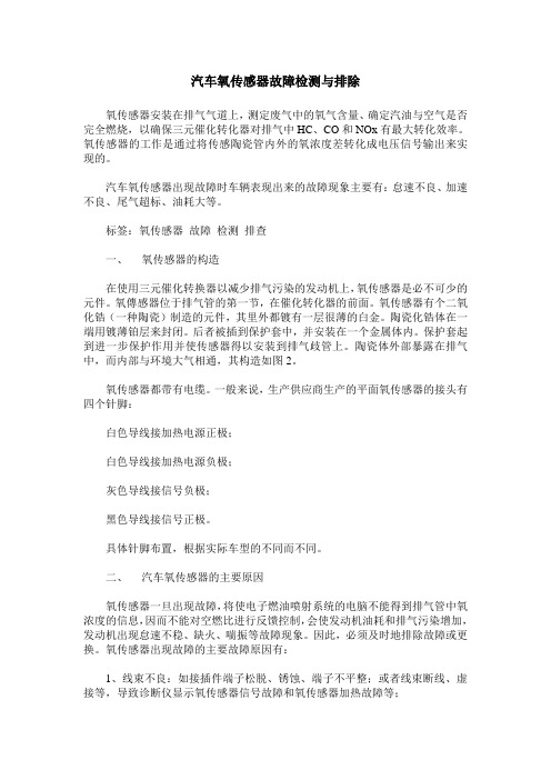
汽车氧传感器故障检测与排除氧传感器安装在排气气道上,测定废气中的氧气含量、确定汽油与空气是否完全燃烧,以确保三元催化转化器对排气中HC、CO和NOx有最大转化效率。
氧传感器的工作是通过将传感陶瓷管内外的氧浓度差转化成电压信号输出来实现的。
汽车氧传感器出现故障时车辆表现出来的故障现象主要有:怠速不良、加速不良、尾气超标、油耗大等。
标签:氧传感器故障检测排查一、氧传感器的构造在使用三元催化转换器以减少排气污染的发动机上,氧传感器是必不可少的元件。
氧傳感器位于排气管的第一节,在催化转化器的前面。
氧传感器有个二氧化锆(一种陶瓷)制造的元件,其里外都镀有一层很薄的白金。
陶瓷化锆体在一端用镀薄铂层来封闭。
后者被插到保护套中,并安装在一个金属体内。
保护套起到进一步保护作用并使传感器得以安装到排气歧管上。
陶瓷体外部暴露在排气中,而内部与环境大气相通,其构造如图2。
氧传感器都带有电缆。
一般来说,生产供应商生产的平面氧传感器的接头有四个针脚:白色导线接加热电源正极;白色导线接加热电源负极;灰色导线接信号负极;黑色导线接信号正极。
具体针脚布置,根据实际车型的不同而不同。
二、汽车氧传感器的主要原因氧传感器一旦出现故障,将使电子燃油喷射系统的电脑不能得到排气管中氧浓度的信息,因而不能对空燃比进行反馈控制,会使发动机油耗和排气污染增加,发动机出现怠速不稳、缺火、喘振等故障现象。
因此,必须及时地排除故障或更换。
氧传感器出现故障的主要故障原因有:1、线束不良:如接插件端子松脱、锈蚀、端子不平整;或者线束断线、虚接等,导致诊断仪显示氧传感器信号故障和氧传感器加热故障等;2、飞石等机械冲击造成传感器损坏。
3、湿汽、冷凝水或污染物进入传感器内部,造成传感器失效或信号不良;4、由于失火引起的排气管道后燃,使得氧传感器传感元烧损;5、氧传感器“中毒”(如Pb、S、Br、Si、Mn等);三、氧传感器的检测与排查首先实施的排查方法(针对线束及接插件):1、检查氧传感器加热控制线(两根白线)、信号线(黑色)和信号接地线(灰色)是否存在开路或短路,如果存在,则更换线束。
OBD相关设置
应用技术公告(Calterm版本)标题AEB用于下列应用类型:OBD相关设置汽车工业用发电船机日期:2009年3月AEB Number :CFWI_033 发动机机型包括:ISDe4 ISLe4 ISZ作者:柯采批准人:第1/ 页我们编写此电子子系统技术文件是为了在OEM 设计和与发动机电子系统和电气部件接口连接方面提供帮助。
本手册包含了OEM 编程指南。
本文件及其内容属于机密和专有信息,不得以复印文件或电子文件形式向第三方披露。
1. OBD概述1.1 车载诊断系统(OBD)是一个可以用来检测排放控制系统故障的自诊断系统。
它自动诊断排放系统故障并将这些信息传达给车辆驾驶人员。
1.2 OBD系统检测影响发动机排放的各个部件,保证车辆在其整个寿命周期内能持续满足排放法规的要求。
如果一个故障被检测到,OBD系统将点亮汽车仪表盘上的故障指示灯来警示驾驶人员。
1.3 OBD系统自动存储检测到的故障信息,通些这些信息汽车修理人员能准确地发现和排除故障。
1.4 通过公共的通信接口,用通用的OBD诊断设备可以读取诊断信息。
2. OBD功能基本设置3. 限扭矩的OBD故障代码4. OBD 对NOx排放量的监控当满足以下条件,NOx monitor开始工作:C_SCD_flm_NM_PassMinInj <V_UIM_flm_EstUreaInjRate<C_SCD_flm_NM_PassMaxUreaInjV_SCP_trc_SCR_Bed >C_SCD_trc_NM_PassMinNOx monitor开始工作后,取样时间由C_SCD_tm_NM_PassSampleTime决定,当取样次数达到C_SCD_ct_NM_PassCntLim规定的次数后,计算V_SCD_ppm_NM_PassErrAvg=P_SCD_ppm_NM_PassScrTotal/C_SCD_ct_NM_PassCntLim,然后用V_SCD_ppm_NM_PassErrAvg的值与C_SCD_ppm_NM_PassTooHighLim 和C_SCD_ppm_NM_PassDrtLim做比较:C_SCD_ppm_NM_PassTooHighLim<V_SCD_ppm_NM_PassErrAvg<C_SCD_pp m_NM_PassDrtLim, 报故障代码2772,但发动机不降扭矩。
电极极化及其对NOx传感器剩余氧气浓度的影响
图 1 西 门子 /G N K公 司的 N 感器 的控 制模 式 0传
收 稿 日期 :0 7 0 一 9 20 — 6 t
作者简介: 唐玲( 9 7 , 安徽淮北人 , 15 一)女, 蚌埠 医学院讲师 , 主要从事医学化学教学 。
维普资讯
。
柴 油 发 动 机 中燃 料 的 燃 烧 是 不 均 匀 的 。柴 油 汽 车 释 放 的 NO ( 氧 化 物 ) 成 的 空 气 污 染 是 一 个 很 严 重 氮 造
的 问 题 。汽 车 工 业 界 投 入 了很 大 的 精 力 去 发 展 具 有 汽 牟 尾 气 实 时 测 世 催 化 剂 诊 断 系 统 以 及 尾 气 消 除 系 统 , 满 足 尾 气 的 排 放 控 制 标 准 。这 些 系 统 中 , 体 传 感 器 是 非 常 重 要 的 , 以采 集 排 放 尾 气 的信 号 , 以 气 可 从 而 实 现 对 发 动 机 运 转 状 态 的 监 控 。目前 , 备 化 学 发 光 和红 外 光 谱 的 分 析 设 备 被 用 来 测 NO 配 x的 含 量 , 这 些 设 备 价 格 昂 贵 、 积 庞 大 , 能 在 交 通 丁 具 使 用 。 因此 , 人 探 索 在 汽 油 发 动 机 t 配 务 紧 凑 而 价 体 不 卜 有 廉 的 氧 气 传 感 器 , 应 用 于 催 化 控 制 系 统 和 发 动 机 控 制 系统 【 日本 的 NGK公 司 和 德 国 的 西 门 子公 司联 并 1 I , 合 研 制 了 NO 传 感 器 1 1给 出 了 西 门 子 / 2 图 。 NGK 公 司 的 NO 传 感 器 的 控 制 模 式 示 意 网 。 该 传 感 器 由 x 两 个 『 部 腔 、 个 氧 气 泵 电池 和 一 个 力 I 器 组 成 。 传 感 器 的 l 作 过 程 包 括 两 步 : 人 J 三 I 热 丁 旨先 , 测 撮 气 体 中 被 的 氧 气 浓 度 在 内 腔 1巾被 调 节 到 事 先 设 定 的 水 平 , 时 NO 此 没 有 分 解 。 后 , 内腔 2巾氧 气 浓 度 进 一 然 在 步 降 低 到 另 一 个 事 先 设 定 的 水 平 , 在 测 量 电 极 』 利 用 NO N0 二 还 原 催 化 剂 分 解 ,剩 余 氧 气 的 浓 度 用 3 5mV的 V1电 压 测 和 控 制 。第 二 个 氧 气 泵 电 池 j施 加 7 A 的恒 定 电 流 , V1~ 定 剩 余 氧 气 浓 8 - 与 卜测 度 的 阎 定 电 压 一 起 控 制 剩 余 氧 气 的 浓 度 。C 和 碳 氧 化 合 物 分 子在 第 一 个 氧 气 泵 电 池 中 被 氧 化 , : O NO 在 第 二个 氧 气 泵 电池 巾被 还 原 成 NO, 有 N 、 O、 只 : H: CO:NO和 剩 余 的 氧 气 到 达 NO 、 泵 电池 。 测 电 极 上 施 加 4 0mV的 恒 定 电 压 , 考 电极 暴 露 在 环 境 空 气 巾 。 在 测 气 体 时 , 过 测 量 电 极 的 电 流 与 NO 0 参 通 x
基于杂多酸修饰电极NOx传感器的制备与应用
谱 法[ ] , 中电化 学 法 中 的化 学 修饰 电极 [ ] 等 其 以 其 独特 的化 学性 能在 分 析 检 测领 域 得 到 了不 断发 展 , 在 提 高选择 性和 灵敏 度方 面具有 独特 的优越性 。而 电
氮氧化 物 ( O ) 类 很 多 , N 种 主要 是 一 氧 化 氮 和二
氧化氮 , 以二 氧 化 氮 为 主 , 是 一 种 重 要 的大 气 污 染 且 物 , 造成 酸雨 , 易 对金 属 、 械 、 筑物等 都有 明显 的腐 机 建
蚀 作用 ; 也会 对 臭氧层 产生 破坏作 用 , 严重 的环境 造成 污染现 象 …。 同时 它还 能 刺 激 和损 害 呼 吸系 统 , 害 1 伤
7H 8 W一1 型恒温磁力搅拌器 ; 超声波 清洗器 ; 三电极 系统 以玻碳 电极 为基体 的 A u—Mo 修饰 电极 为工 作 电 极 , A C 电极 为参 比电极 , A gl 铂丝 为辅 助 电极 。
A u标准溶 液 (m / 1 : 1 g m ) 电极 的修饰 液 为含 A . u0 2
YAN l We i
( oee f ni n et c ne adE g er gA hi om l n e i , h 304 C i ) C lg v om n l i cs n ni ei ,n u N r a U i rt Wuu2 10 , h a l oE r a Se n n v sy n
Ke r s: eeo l cd; h mia dfe lcrde NOx y wo d h tr p y a i c e e Uy mo i d ee to ; o i
盛思锐 I2C 接口描述 SVM41 VOC 和 NOx 室内空气质量传感器测量 应用说明书
I2C Interface Description SVM41Evaluation Board for SGP40 and SGP41 – Indoor Air Quality Sensor for VOC and NO x MeasurementsTable of Contents1 General Considerations (2)2 I2C Sequences (3)3 Checksum Calculation (4)4 I2C Commands (5)1General ConsiderationsFor detailed information about the I2C protocol itself and its detailed implementation, please, consult the document NXP I2C-bus specification and user manual. All SVM41 commands consist of two bytes (16 bits). The commands must not be followed by a CRC. Additionally, data sent to and returned from the sensor is transferred in packets of two bytes (16 bits) followed by a 1-byte (8 bit) CRC.1.1I2C AddressThe sensor’s I2C address is 106 (decimal; hex.: 0x6A). The I2C header is formed by the I2C address followed by a read or write bit.1.2I2C Voltage LevelsInput and output voltage levels are specified in section 6.1 of NXP I2C-bus specification and user manual. The sensor’s interface is compatible with 3.0–5.5 V I2C bus voltage levels depending on the supply voltage level.1.3I2C Protocol SpeedThe sensor supports I2C “standard-mode” with a maximum clock frequency of 100 kHz.2I2C SequencesThe typical communication sequence between the I2C master (e.g., a microcontroller in a host device) and the SVM41 is described as follows and visualized in Figure 1:1.T he SVM41 is powered up2.T he I2C master starts the measurement of all sensors by calling the dedicated command.3.T he I2C master periodically calls the get signals command and reads data in the following sequence:a.I2C master sends a get signals command.b.I2C master either waits for the expected duration (as listed in Table 2) or polls data until the read header is acknowledgedby the slave.c.I2C master reads out the signal data.4.T he I2C master may stop the measurement by sending the dedicated command.With the acknowledgement of the start measurement command, both SGP41 and STH4x start measuring. Measurement data are continuously stored on the microcontroller with a sampling interval of 1 s. Resulting data can be retrieved at any time by sending one of the get signals commands. In case the sampling interval by the I2C master is higher than 1 s the slave will respond with the same data for 1 s. When the execution of the command is in progress, no communication with the sensor is possible and the sensor aborts the communication with a NACK condition. After sending one of the get signals commands, the master can read the measurement results by sending an I2C read header. The sensor will acknowledge the reception of the read header and responds with data. The response data length is listed in Table 2 and is structured in data words, where one word consists of two bytes of data (most significant bit first) followed by a one-byte CRC checksum. Each byte must be acknowledged by the master with an ACK condition for the sensor to continue sending data. If the sensor does not receive an ACK from the master after any byte of data, it will not continue sending data.After receiving the checksum for the last word of data, a NACK and STOP condition have to be sent (see Figure 1). The I2C master can abort the read transfer with a NACK followed by a STOP condition after any data byte if it is not interested in subsequent data, e.g., the CRC byte or following data bytes, in order to save time. Note that the data cannot be read more than once, and access to data beyond the specified amount will return a pattern of high bits.Figure 1 Possible I2C command sequences for communicating with the SVM41. Dark areas indicate that theSVM41 controls the SDA (data) line. First, the I2C master sends the write header writing a 16-bit command,potentially followed by one, four, or six words of data with CRC bytes. For reading the measured data, the I2Cmaster sends the read header and receives one, four, or six words of data with CRC byte.3Checksum CalculationThe 8-bit CRC checksum transmitted after each data word is generated by the CRC algorithm according to the properties as stated in Table 1. The CRC covers the contents of the two previously transmitted data bytes.Table 1 Checksums are used for the 2-byte data packets only. The command codes themselves already contain a 3-bit CRC and therefore, a checksum must not be appended.4I2C CommandsThe available measurement commands of the SVM41 are listed in Table 2.Table 2 I2C commands available for SVM41.4.1Start MeasurementTable 3 Description of the I2C start measurement command.4.2Get SignalsTable 4 Description of the I2C get signals command.Table 5 Returned values by the I2C get signals command.4.3Get Raw SignalsTable 6 Description of the I2C get raw signals command.Table 7 Returned values by the I2C get raw signals command.4.4Stop MeasurementTable 8 Description of the I2C stop measurement command.4.5Get/Set Temperature Offset for RHT MeasurementsTable 9 Description of the I2C get/set temperature offset command.Table 10 Returned/input values by the I2C get/set temperature offset command.Table 11 Description of the I2C get/set VOC parameters command.Table 12 Returned/input values by the I2C get/set VOC parameters command.Table 13 Description of the I2C get/set NO x parameters command.Table 14 Returned/input values by the I2C get/set NO x parameters command.4.8Store Input Parameters to Non-Volatile MemoryTable 15 Description of the I2C store input parameters command.4.9Get/Set States of VOC AlgorithmTable 16 Description of the I2C get/set VOC states command.Table 17 Returned/input values by the I2C get/set VOC states command.4.10Get Version of DeviceTable 18 Description of the I2C get device version command.Table 19 Returned values by the I2C get device version command.4.11Device ResetTable 20 Description of the I2C reset device command.Revision HistoryCopyright© 2021 by SENSIRION CMOSens® is a trademark of SensirionAll rights reservedHeadquarters and SubsidiariesSensirion AG Laubisruetistr. 50CH-8712 Staefa ZH Switzerlandphone: +41 44 306 40 00 fax: +41 44 306 40 30 ****************** Sensirion Inc., USAphone: +1 312 690 5858*********************Sensirion Korea Co. Ltd.phone: +82 31 337 7700~3*********************/kr Sensirion Japan Co. Ltd.phone: +81 3 3444 4940*********************/jpSensirion China Co. Ltd.phone: +86 755 8252 1501*********************/cnSensirion Taiwan Co. Ltdphone: +886 3 5506701****************** To find your local representative, please visit /distributors。
氧传感器资料
氧传感器资料第1楼:深入了解氧传感器(转自:pcauto)前言:相信看过许多杂志、书籍或是在本站上的一些文章,都有遇上这类的话题,也应该大略了解其作用。
不过在本篇将更详尽的叙述到氧传感器的种类,及在引擎回馈控制与废气管理上的作用与重要性。
在这里我们也介绍到如何利用示波器来截取氧传感器之讯号,并加以判断其作用、控制、回馈及性能好坏。
一、氧传感器的构造与作用在讨论氧传感器(Oxygen Sensor 或简称 O2 sensor)之前,我们先来研究引擎燃烧后所产生的有害废气。
一般汽车所排放的废气特别是对人体有害的,主要有三种:一氧化碳(CO)、碳氢化合物(HC)、氮氧化物(NOx),其中 CO,HC 只要使汽油完全地燃烧即可将这两者废气减至最低,然而当汽油达到完全燃烧时温度容易升高,连带的也就使得NOx剧增,在这部份可利用EGR来减少其发生量。
但这对于废气的管制显然还不够的,要使引擎所有的转运范围皆达到其控制标准,因此加入了三元触媒转化器( Three-Way Catalyst Converter 或简称 TWC)的控制。
触媒转化器基本上就是氧化与还原的作用,如图所示内部有着极为细微的孔洞并含有大量的贵金属:铂(氧化触媒)及铑(还原触媒),它能将上述三种有害的气体藉由氧化及还原的作用,转化成无害的气体或是一般的废气,其化学作用如下:2CO + O2 → 2CO22C2H6 + 2CO → 4CO2 + 6H2O2NO + 2CO → N2 + 2CO2有无触媒所造成的废气影响然而触媒转化器的使用条件相当严苛,除了须达到较高工作温度外,最重要的是它的最大净化率是发生在理论混合比附近(14.7:1)如上图,也就是说引擎的燃烧须控制在14.7:1 空燃混合之下,要达到此细微之标准并不容易,所以才藉由氧传感器的作用将空燃比转换成数据供给引擎计算机进而调整到理论范围,稍后也将述说到引擎计算机如何利用含氧感知的讯号来作回馈的作用,使其空燃比维持在14.7:1附近。