锁相技术译文翻译
锁相技术及频率合成

技术优势与挑战
技术优势
PLL和FS的结合可以实现快速频率切 换、低相位噪声、高分辨率等优点。
技术挑战
需要解决PLL和FS之间的相位噪声传 递和杂散抑制等问题,以确保输出信 号的质量。
实际应用案例
通信系统中的频率合成
用于产生稳定的本振信号,确保接收和发射信号的稳定性和准确 性。
雷达系统中的频率合成
锁相技术原理
锁相技术的基本原理是利用负反馈控制,将外部输入信号与 内部振荡信号进行相位比较,并根据比较结果调整内部振荡 器的参数,使两者的相位保持一致。
当外部输入信号的频率与内部振荡信号的频率相差较小时, 锁相环能够自动跟踪输入信号的频率,并保持两者之间的相 位差恒定。
锁相技术的应用
锁相技术在通信、雷达、导航 、测量等领域得到广泛应用。
智能化
利用人工智能和机器学习技术,实 现锁相技术及频率合成的智能化控 制,提高系统的自适应性。
研究热点与前沿
宽频带、高精度频率合成
01
研究宽频带、高精度频率合成技术,以满足通信、雷达、电子
对抗等领域的需求。
快速频率跳变
02
研究快速频率跳变技术,实现快速切换和灵活的通信方式,提
高通信系统的抗干扰能力和保密性。
电子对抗
在电子对抗领域,锁相技术和频率合成技术用于生成干扰信号和探测信
号,对于提高电子设备的抗干扰能力和探测能力具有重要作用。
02
锁相技术概述
锁相技术定义
Байду номын сангаас
01
锁相技术是一种通过相位比较和 调整实现信号频率跟踪和锁定相 位的电子技术。
02
它利用外部输入信号与内部振荡 信号的相位比较,自动调整内部 振荡器的参数,使两者的相位保 持一致。
锁相技术课件
一、概述
§6.3 频率合成
1. 概念
频率合成器是将一个高精确度和高稳定度的标准
参考频率,经过混频、倍频与分频等对它进行加、
减、乘、除的四则运算,最终产生大量的具有同样
精确度和稳定度的频率源。
2. 应用 频率合成器在雷达、通信、遥控遥测、电视广
播和电子测量仪器等方面得到了广泛的应用。
《锁相技术》
第6章 锁相环路的应用
于He (s)具有高通特性,只要在He (s) 的通带之内,
输出信号频偏正比于调制信号的幅度。----调频波
调相波:
2
(s)
He (s)
Ko s
sU F
(s)
对调制信号先 微分再调频
2 (s) He (s)KoUF (s)
输出信号相位正比于调制信号的幅度。----调相波
《锁相技术》
第6章 锁相环路的应用
音频信号调频,则输入瞬时频率为:
载频
i (t) c sin t
Δω为峰 值频偏
当 0 时,i c ,所以 实际是叠加到c 上的。
做出 H ( ji ) i 的关系图,就是环路对输入信号 瞬时频率i 的振幅频率响应:
《锁相技术》
第6章 锁相环路的应用
-3dB点
2c
① 具有带通滤波特性。带宽为 2c 。 ② 由于锁相环的跟踪性能,其中心频率可以跟踪输
fd
fo N V
fo N Vfr
①增加前置分频器,解决了输出频率高于程序分频
器的工作频率的问题,提高了输出频率范围。
《锁相技术》
第6章 锁相环路的应用
②输出频率增量为Vfr ,频率分辨率降低了。
③如果保持原有的频率分辨率 fr ,需要使参考频率
锁相技术学习心得体会doc
锁相技术学习心得体会篇一:锁相技术锁相技术论文题目:专业班级:学生姓名:学号:任课老师:陈燕锁相技术的核心 XX级通信工程1班 XX 年 6 月13日摘要本文介绍了锁相技术的核心锁相环路:一个实现相位自动锁定的控制系统。
锁相环路有两个突出的特性:1是窄带滤波特性;2是宽带跟踪特性。
这两个特性使得锁相技术在电子技术领域得到了广泛的应用,特别是随着集成电路技术、数字技术以及通讯和计算机技术的发展,极大地推动了锁相技术的发展和应用。
现在锁相技术已经形成一门比较系统的理论科学,锁相技术的应用主要包含以下几个方面:跟踪滤波、频率合成与频率变换、模拟和数字信号的相干解调、数字通讯、调制与解调、检波、稳频和位频等。
下面来主要介绍一下锁相技术的核心,掌握核心就能运用得当。
关键字:核心,锁相环路,运用锁相环路的工作原理:锁相环路是一种反馈电路,锁相环的英文全称是Phase-Locked Loop,简称PLL。
其作用是使得电路上的时钟和某一外部时钟的相位同步。
因锁相环可以实现输出信号频率对输入信号频率的自动跟踪,所以锁相环通常用于闭环跟踪电路。
锁相环在工作的过程中,当输出信号的频率与输入信号的频率相等时,输出电压与输入电压保持固定的相位差值,即输出电压与输入电压的相位被锁住,这就是锁相环名称的由来。
在数据采集系统中,锁相环是一种非常有用的同步技术,因为通过锁相环,可以使得不同的数据采集板卡共享同一个采样时钟。
因此,所有板卡上各自的本地 80MHz和20MHz 时基的相位都是同步的,从而采样时钟也是同步的。
因为每块板卡的采样时钟都是同步的,所以都能严格地在同一时刻进行数据采集。
锁相环路是一个相位反馈自动控制系统。
它由以下三个基本部件组成:鉴相器(PD)、环路滤波器(LPF)和压控振荡器(VCO)。
锁相环的工作原理:1. 压控振荡器的输出经过采集并分频;2. 和基准信号同时输入鉴相器;3. 鉴相器通过比较上述两个信号的频率差,然后输出一个直流脉冲电压;4. 控制VCO,使它的频率改变;5. 这样经过一个很短的时间,VCO 的输出就会稳定于某一期望值。
锁相技术——张厥盛 第三章
20)式可得
n BL (1 4 2 ) 8
(3-25)
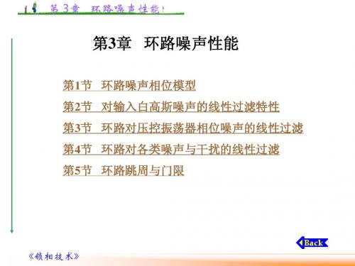
《锁相技术》
第 3章 环路噪声性能
图3-5 采用简单RC积分滤波器二阶
《锁相技术》
第 3章 环路噪声性能
图3-6 理想二阶环的BL/ωn~ζ关系曲线
《锁相技术》
第 3章 环路噪声性能 4.采用无源比例积分滤波器的二阶环采用与有源比 例积分滤波器的二阶环相同的方法,可得
(3-3)
(3-4)
e ( t ) 1 ( t ) 2 ( t )
Ud Ud N (t ) [ne (t ) cos 2 (t ) ne (t ) sin 2 ( t )] n ( t ) (3-5) Ui Ui 1 U d K mU iU o 2
《锁相技术》
s
《锁相技术》
2 ( s)
第 3章 环路噪声性能
图3-3 有输入噪声时环路线性化噪声相位模型 《锁相技术》
(a)等效为N(s); (b)等效为θni(s)
第 3章 环路噪声性能
因此得
N ( s ) F ( s ) Ko KF ( s ) N ( s) N ( s) s 2 ( s) H ( s) KF ( s ) s KF ( s ) K d Kd 1 s 2 s ) H ( s ) ni ( s )
相位模型如图3-10所示。
Ko F ( p ) 2 (2) [U d sin e (t ) N (t )] p d e d1 Ko F ( p )[U d sin e (t ) N (t )] dt dt
(3-6)
(3-7)
《锁相技术》
第 3章 环路噪声性能
第八章锁相技术5-1(原理)

频率是频差 (i o ),称差拍正弦 ~ ② 鉴相范围是: 2 2 ③ 鉴相特性为非线性,
当 e
vd (t ) Ud sin e (t ) Ude (t )
④ 正弦鉴相器的鉴相灵敏度为: Ad
6
时 ,正弦鉴相可以近似为线性
dvd d e
Ud
e 0
e (t ) i (t ) o (t )
该方程表示了环路中动态角频率的平衡关系: 瞬时频差 = 输入固有频差 — 控制频差
从以下几点加深对环路方程的理解:
vi
vi Vim sin[r t i (t )]
U d sin()
vd
vc
vo Vom cos[r t o (t )]
vc (t )
VCO
vo (t )
o (t ) r Ao vc (t )
r —— 控制电压 vc =0 时的自由振荡角频率
Ao 压控灵敏度,其单位是(弧度/秒)/伏
锁相环中VCO 数学模型
vi
vd
vc
vo
注意:VCO电压输入鉴相器,起作用的是其相位
U d sin e
求VCO受控相位: o ( )d r t A v ( )d
常用的环路滤波器三种环路滤波器的传递函数时间常数rc无源比例积分滤波器分子引入一个零点低通特性与简单rc滤波器不同趋于比例常数而不是环路滤波器的主要指标相频特性比例积分滤波器的传递函数中引入了一个零点使相频特性在频率较高处有相位超前校正作用这利于增加环路的稳定性直流增益有源滤波器直流增益很大利于环路同步带宽由滤波器的时间常数决定高频增益比例积分滤波器不为0利于环路的捕捉幅频特性低通特性压控振荡器vcovco功能电压控制频率振荡器频率受控特性理想的应为线性
锁相技术译文翻译
锁相技术译文翻译英文原文:An On-Chip All-Digital Measurement Circuit to Characterize Phase-Locked Loop Response in 45-nm SOI译文:45纳米SOI全数字片上测量电路表征锁相环响应特性年级专业:姓名:学号:2013 年 6 月 2 日英文中文An On-Chip All-Digital Measurement Circuit to Characterize Phase-Locked Loop Response in 45-nm SOIAbstract—An all-digital measurement Circuit , built in 45-nm SOI-CMOS enabl es on-chip characterization of phase-loc ked loop (PLL) response to a self-induce d phase step.This technique allows estimationof PLL closed-loop bandwidth and jitterpeaking. The circuit canbe used to plot step-response vs.time, measure static phase error,and observe phase-lock status. INTRODUCTIONMany applications such as PCI Express ? require a PLL to produce alow-jitter cl ock at a given frequency while meeting stringent bandwidth and jitter peaking r 45纳米SOI全数字片上测量电路表征锁相环响应特性摘要---建立在45纳米的SOI-CMOS上一个全数字测量电路,它能够表征PLL对自诱导相步进的响应这项技术允许对PLL闭环带宽和抖动峰值的估计。
锁相环英文文献翻译
锁相技术译文翻译英文原名:High Speed Digital Hybrid PLL Frequency Synthesizer译文:高速数字混合锁相环频率合成器年纪专业:08级通信工程班姓名:学号:2011年 5月2日To get the high-speed, it is necessary to prepare the precise synchronization of the complicated design.In 2001, H. G. Ryu proposed a simplified structure of the DDFS (direct digital frequency synthesizer)-driven PLL for the high switching speed [2].However, there is a problem that the speed of the whole system is limited by PLL.Y. Fouzar proposed a PLL frequency synthesizer of dual loop configuration using frequency-to-voltage converter (FVC) [3].It has a fast switching speed by the PD (phase detector), FVC using output signal of VCO and the proposed coarse tuning controller.However, H/W complexity is increased for the high switching speed.Also, it shows the fast switching characteristic only when the FVC works well.Another method is pre-tuning one which is called DH-PLL in this study [4].It has very high speed switching property, but H/W complexity and power consumption are increased due to digital look-up table (DLT) which is usually implemented by the ROM including the transfer characteristic ofVCO(voltage controlled oscillator).For this reason, this paper proposes a timing synchronization circuit for the rapid frequency synthesis and a very simple DLT replacement digital logic block instead of the complex ROM type DLT for high speed switching and low power consumption. Also, the requisite condition is solved in the proposed method. The fast switching operation at every the frequency synthesis process is verified by the computer circuit simulation.II.DH-PLL synthesizerAs shown in Fig.1, the open-loop synthesizer is a direct frequency synthesis type that VCO 要得到高运行速度,事先做好复杂设计的精确同步是必要的。
锁相技术
设输出信号为:uo (t) Uo cos[ot o (t)]
PLL内部VCO的 自由振荡角频率
是在输入信号控制下,
相对于 ot的瞬时相位,
是时间 t 的函数。
锁相环路中,输入信号 ui (t) 对环路的作用是 在它的瞬时相位 i (t) i (t) 的作用下,改变输出 信号 uo (t) 的瞬时相位 o (t) o (t) ,所以对于锁相 环路来说,更关心的是它的输入和输出信号的相
不为零
数值很小 的量,但
不为零
这一过程所用的时间为捕获时间 TP
《 锁相技术》
第1章 锁相环路的基本工作原理
捕获过程中瞬时相差与瞬时频差的典型时间图分析
.
《 锁相技术》
第1章 锁相环路的基本工作原理
三、锁定状态
环路锁定状态(同步状态)的条件:
e((tt))
(t) 2n e
K0 p
整理得到:pe (t) p1(t) KoUd F ( p)sine(t)
uc (t)
环路的动态方程:
K KoUd
pe (t) p1(t) KF ( p)sine(t)
K K0Ud 为环路增益
《 锁相技术》
第1章 锁相环路的基本工作原理
锁相环路动态方程的物理概念解释:
第1章 锁相环路的基本工作原理
环路的瞬时相位差:(矢量表示方法如图所示)
e (t) 1(t) 2(t)
输入信号的 瞬时角频率
输出信号的 瞬时角频率
环路瞬时频差:
de (t)
dt
1(t)2 (t)
(t)
e (t)
- 1、下载文档前请自行甄别文档内容的完整性,平台不提供额外的编辑、内容补充、找答案等附加服务。
- 2、"仅部分预览"的文档,不可在线预览部分如存在完整性等问题,可反馈申请退款(可完整预览的文档不适用该条件!)。
- 3、如文档侵犯您的权益,请联系客服反馈,我们会尽快为您处理(人工客服工作时间:9:00-18:30)。
锁相技术译文翻译英文原文:An On-Chip All-Digital Measurement Circuit to Characterize Phase-Locked Loop Response in 45-nm SOI译文:45纳米SOI全数字片上测量电路表征锁相环响应特性年级专业:姓名:学号:2013 年 6 月 2 日英文中文An On-Chip All-Digital MeasurementCircuit to Characterize Phase-LockedLoop Response in 45-nm SOIAbstract—An all-digital measurement Circuit , built in 45-nm SOI-CMOS enables on-chip characterization of phase-locked loop (PLL) response to a self-induced phase step.This technique allows estimationof PLL closed-loop bandwidth and jitterpeaking. The circuit canbe used to plot step-response vs.time, measure static phase error,and observe phase-lock status. INTRODUCTIONMany applications such as PCI Express? require a PLL to produce alow-jitter clock at a given frequency while meeting s tringent bandwidth and jitter peaking r 45纳米SOI全数字片上测量电路表征锁相环响应特性摘要---建立在45纳米的SOI-CMOS上一个全数字测量电路,它能够表征PLL对自诱导相步进的响应这项技术允许对PLL闭环带宽和抖动峰值的估计。
这个电路被用来绘制阶跃响应随时间变化的曲线,测量静态相位误差和观察相位锁定状态。
介绍很多应用例如PCI Express?需要一个PLL来产生一个低抖动的在一个给定频率的时钟,这个频率满足精确带宽和抖动峰值的要求。
equirements. Process, voltage, and tem perature (PVT) variations as well as rand om device mismatch make it difficult toguarantee a narrow range for PLL resp onse. For example ,loop parameters suc h as VCO gaincould vary by more than 2X overPVT corners. In Fig. 1, we see the closed-loop jitter transfer functions of two PLLs with identical reference clock and output frequencies. One PLL exhibits largepeaking and low bandwidth while theother shows little peaking but high ban dwidth. Although differences in this exa mple are more extreme than usual, similar but smaller differences often result from PVT variations.PLL response is often measured on atest bench using signal generators, osci lloscopes, and/or spectrum analyzers.For example, the transfer functions in Fi 工艺,电压,和温度(PVT)变化以及随机的选择不搭配的器件都使得很难保证一个窄的变化范围的PLL响应,例如,环路参数如VCO增益变化可能超过PVT角2倍上以。
图一中,我们可以看到两个具有相同参考时钟和输出频率PLL的闭环抖动传递函数一个PLL展现大的峰值和低带宽,而另一个展示了小峰值但是高带宽虽然这个例子中显示的差异比通常的要极端,这种相似会随着PVT的变化而变小PLL的响应往往使用一个信号发生器、示波器,和/或频谱分析仪。
g. 1 were automatically generated by modulating the 100-MHz reference clock with various frequencies while observin g the amplitudes of the resulting output spurs. Such methods, which may requi re many seconds to complete, motivate the need for faster, less expensive, and preferably on-chip techniques to charac terize PLL response [1]-[3]. Fig. 2 shows the PLL output phase transient respons e to an induced phase step. Similar to other second-order feedback systems, t he PLL tends to overcorrect (or oversho ot) as it works to eliminate the induced phase error. If the PLL is underdamped, as in this example, the PLL may ring sev eral times before settlingto its final lock state. A key metric in the PLL step-resp onse is crossover, defined here as the elapsed time from input step toonset of phase overshoot. Another key metric is MaxOvershoot. It 例如,在图一中传递函数是通过调制100MHz能产生各种频率的参考时钟同时观察输出马刺产生的幅值自动生成的。
这种方法,可能需要一些时间去完成,这促进了更快,更便宜的方法的需要。
比较好的方法是片上系统来表征PLL的响应特性[1]-[3]。
表二表明致相步进响应的输出瞬态相位。
类似于其他二阶反馈系统,PLL倾向于过调(或过调),那是因为它是为了消除相位误差。
如果锁相环工作在欠阻尼状态,在这种状态下,PLL可能要经过几次锁存在达到最终锁measures the maximum overcorrectionin the step response.Transient simulations and closed-form loop equations [4] show that crossover is inversely proportional to the PLL’s 3dB closed-loop bandwidth; the smaller crossoveris, the higher the bandwidth (Fig. 3). Notice that crossover is largely independent of the size ofthe phasestep. Both simulations and loop equations also predict that MaxOvershoot is p roportional to the maximum peaking inthe closed-loop transfer function; the larger MaxOvershoot is, the greaterthe peaking (Fig. 4). Notice thatthe magnitude of the overshoot isalso proportional to theinput stepsize .These relations hips between time- and frequency-domain behaviors allow us to make fast time-domain measurements and then relate the results back to frequency-domain performance specifications. The 存状态之前锁相环阶跃响应的一个关键指标是交叉反应。
在此定义为从输入步进到相位超调开始出现所用的时间另一个关键指标是最大超调量。
它可以测量阶跃响应的最大过调量。
瞬态模拟和闭环回路方程[4]表明交叉反应和PLL的3dB闭环带宽成反比;交叉反应越小,带宽越大(图3)。
请注意,交叉反应在很大程度上与相位步长无关。
模拟和回路方程还预测到闭环传递函数中最大超调与最大峰值是成正比的;circuitimplementation presented in this papershows that the PLL step response maybe captured byanall-digital, on-chip finite statemachine, allowing for fast PLL characterization.Silicon results indicate that this circuit could allow for Power-on calibration of the PLL bandwidth and peaking for com pensation of process variations.CIRCUIT DESIGNThe PLL under test (Fig. 5) isa standard integer-N charge-pump PLL. The only modification is theaddition of loop measurement circuitry.The feedback divisor (N) isprogrammable from 5 to 63 ,although N>=8 during loop measurement tests. The charge-pump current, loop-filter resistance, and VCO gain are pro grammable to allow for bandwidth andpeaking adjustments aswell as jitter opt 最大超调越大,峰值越高(图4)。