
汽车转向系统中英文外文翻译
中英文对照资料外文翻译文献Spin control for carsStability control systems are the latest in a string of technologies focusing on improved diriving safety. Such systems detect the initial phases of a skid and restore directional control in 40 milliseconds, seven times faster than the reaction time of the average human. They correct vehicle paths by adjusting engine torque or applying the left- or-right-side brakes, or both, as needed. The technology has already been applied to the Mercedes-Benz S600 coupe.Automatic stability systems can detect the onset of a skid and bring a fishtailing vehicle back on course even before its driver can react.Safety glass, seat belts, crumple zones, air bags, antilock brakes, traction control, and now stability control. The continuing progression of safety systems for cars has yielded yet another device designed to keep occupants from injury. Stability control systems help drivers recover from uncontrolled skids in curves, thus avoiding spinouts and accidents.Using computers and an array of sensors, a stability control system detects the onset of a skid and restores directional control more quickly than a human driver can. Every microsecond, the system takes a "snapshot," calculating whether a car is going exactly in the direction it is being steered. If there is the slightest difference between where the driver is steering and where the vehicle is going, the system corrects its path in a split-second by adjusting engine torque and/or applying the cat's left- or right-side brakes as needed. Typical reaction time is 40 milliseconds - seven times faster than that of the average human.A stability control system senses the driver's desired motion from the steering angle, the accelerator pedal position, and the brake pressure while determining the vehicle's actual motion from the yaw rate (vehicle rotation about its vertical axis) and lateral acceleration, explained Anton van Zanten, project leader of the Robert Bosch engineering team. Van Zanten's group and a team of engineers from Mercedes-Benz, led by project manager Armin Muller, developed the first fully effective stability control system, which regulates engine torque and wheel brake pressures using traction control components to minimize the difference between the desired and actual motion.Automotive safety experts believe that stability control systems will reduce the number of accidents, or at least the severity of damage. Safety statistics say that most of the deadly accidents in which a single car spins out (accounting for four percent of all deadly collisions) could be avoided using the new technology. The additional cost of the new systems are on the order of the increasingly popular antilock brake/traction control units now available for cars.The debut of stability control technology took place in Europe on the Mercedes-Benz S600 coupe this spring. Developed jointly during the past few years by Robert Bosch GmbH and Mercedes-Benz AG, both of Stuttgart, Germany, Vehicle Dynamics Control (VDC). in Bosch terminology, or the Electronic Stability Program (ESP), as Mercedes calls it, maintains vehicle stability in most driving situations. Bosch developed the system, and Mercedes-Benz integrated it into the vehicle. Mercedes engineers used the state-of-the-art Daimler-Benz virtual-reality driving simulator in Berlin to evaluate the system under extreme conditions, such as strong crosswinds. They then put the system through its paces on the slick ice of Lake Hornavan near Arjeplog, Sweden. Work is currently under way to adapt the technology to buses and large trucks, to avoid jack-knifing, for example.Stability control systems will first appear in mid-1995 on some European S-Class models and will reach the U.S. market during the 1996 model year (November 1995 introduction). It will be available as a $750 option on Mercedes models with V8 engines, and the following year it will be a $2400 option on six-cylinder 鉣俕嶏핤딿냷 $1650 of the latter price is for the traction control system, a prerequisite for stability control.Bosch is not alone in developing such a safety system. ITT Automotive of Auburn Hills, Mich., introduced its Automotive Stability Management System (ASMS) in January at the 1995 North American International Auto Show in Detroit. "ASMS is a quantum leap in the evolution of antilock brake systems, combining the best attributes of ABS and traction control into a total vehicle dynamics management system," said Timothy D. Leuliette, ITT Automotive's president and chief executive officer."ASMS monitors what the vehicle controls indicate should be happening, compares that to what is actually happening, then works to compensate for the difference," said Johannes Graber, ASMS program manager at ITT Automotive Europe. ITT's system should begin appearing on vehicles worldwide near the end of the decade, according to Tom Mathues, director of engineering of Brake & Chassis Systems at ITT Automotive North America. Company engineers are now adapting the system to specific car models from six original equipment manufacturers.A less-sophisticated and less-effective Bosch stability control system already appears on the 1995 750iL and 850Ci V-12 models from Munich-based BMW AG. The BMW Dynamic Stability Control (DSC) system uses the same wheel-speed sensors as traction control and standard anti-lock brake (ABS) systems to recognize conditions that can destabilize a vehicle in curves and corners. To detect such potentially dangerous cornering situations, DSC measures differences in rotational speed between the two front wheels. The DSC system also adds a sensor for steering angle, Utilizes an existing one for vehicle velocity, and introduces its own software control elements in the over allantilock-brake/traction-control/stability-control system.The new Bosch and ITT Automotive stability control systems benefit from advanced technology developed for the aerospace industry. Just as in a supersonic fighter, the automotive stability control units use a sensor-based computer system to mediate between the human controller and the environment - in this case, the interface between tire and road. In addition, the system is built around a gyroscopelike sensor design used for missile guidance.BEYOND ABS AND TRACTION CONTROLStability control is the logical extension of ABS and traction control, according to a Society of Automotive Engineers paper written by van Zanten and Bosch colleagues Rainer Erhardt and Georg Pfaff. Whereas ABS intervenes when wheel lock is imminent during braking, and tractioncontrol prevents wheel slippage when accelerating, stability control operates independently of the driver's actions even when the car is free-rolling. Depending on the particular driving situation, the system may activate an individual wheel brake or any combination of the four and adjust engine torque, stabilizing the car and severely reducing the danger of an uncontrolled skid. The new systems control the motion not only during full braking but also during partial braking, coasting, acceleration, and engine drag on the driven wheels, circumstances well beyond what ABS and traction control can handle.The idea behind the three active safety systems is the same: One wheel locking or slipping significantly decreases directional stability or makes steering a vehicle more difficult. If a car must brake on a low-friction surface, locking its wheels should be avoided to maintain stability and steerability.Whereas ABS and traction control prevent undesired longitudinal slip, stability control reduces loss of lateral stability. If the lateral forces of a moving vehicle are no longer adequate at one or more wheels, the vehicle may lose stability, particularly in curves. What the driveɲ逾半쀹ᾩ쏪 ﲢ끣 "fishtailing" is primarily a turning or spinning around the vehicle's axis. A separate sensor must recognize this spinning, because unlike ABS and traction control, a car's lateral movement cannot be calculated from its wheel speeds.SPIN HANDLERSThe new systems measure any tendency toward understeer (when a car responds slowly to steering changes), or over-steer (when the rear wheels try to swing around). If a car understeers and swerves off course when driven in a curve, the stability control system will correct the error by braking the inner (with respect to the curve) rear wheel. This enables the driver, as in the case of ABS, to approach the locking limit of the road-tire interface without losing control of the vehicle. The stability control system may reduce the vehicle's drive momentum by throttling back the engine and/or by braking on individual wheels. Conversely, if the hteral stabilizing force on the rear axle is insufficient, the danger of oversteering may result in rear-end breakaway or spin-out. Here, the system acts as a stabilizer by applying the outer-front wheel brake.The influence of side slip angle on maneuverability, the Bosch researchers explained, shows that the sensitivity of the yaw moment on the vehicle, with respect to changes in the steeringangle, decreases rapidly as the slip angle of the vehicle increases. Once the slip angle grows beyond a certain limit, the driver has a much harder time recovering by steering. On dry surfaces, maneuverability is lost at slip-angle values larger than approximately 10 degrees, and on packed snow at approximately 4 degrees.Most drivers have little experience recovering from skids. They aren't aware of the coefficient of friction between the tires and the road and have no idea of their vehicle's lateral stability margin. When the limit of adhesion is reached, the driver is usually caught by surprise and very often reacts in the wrong way, steering too much. Oversteering, ITT's Graber explained, causes the car to fishtail, throwing the vehicle even further out of control. ASMS sensors, he said, can quickly detect the beginning of a skid and momentarily activate the brakes at individual wheels to help return the vehicle to a stable line.It is important that stability control systems be user-friendly at the limit of adhesion - that is, to act predictably in a way similar to normal driving.The biggest advantage of stability control is its speed - it can respond immediately not only to skids but also to shifting vehicle conditions (such as changes in weight or tire wear) and road quality. Thus, the systems achieve optimum driving stability by changing the lateral stabilizing forces.For a stability control system to recognize the difference between what the driver wants (desired course) and the actual movement of the vehicle (actual course), current cars require an efficient set of sensors and a greater computer capacity for processing information.The Bosch VDC/ESP electronic control unit contains a conventional circuit board with two partly redundant microcontrollers using 48 kilobytes of ROM each. The 48-kB memory capacity is representative of the large amount of "intelligence" required to perform the design task, van Zanten said. ABS alone, he wrote in the SAE paper, would require one-quarter of this capacity, while ABS and traction control together require only one half of this software capacity.In addition to ABS and traction control systems and related sensors, VDC/ESP uses sensors for yaw rate, lateral acceleration, steering angle, and braking pressure as well as information on whether the car is accelerating, freely rolling, or braking. It obtains the necessary information on the current load condition of the engine from the engine controller. The steering-wheel anglesensor is based on a set of LED and photodiodes mounted in the steering wheel. A silicon-micromachine pressure sensor indicates the master cylinder's braking pressure by measuring the brake fluid pressure in the brake circuit of the front wheels (and, therefore, the brake pressure induced by the driver).Determining the actual course of the vehicle is a more complicated task. Wheel speed signals, which are provided for antilock brakes/traction control by inductive wheel speed sensors, are required to derive longitudinal slip. For an exact analysis of possible movement, however, variables describing lateral motion are needed, so the system must be expanded with two additional sensors - yaw rate sensors and lateral acceleration sensors.A lateral accelerometer monitors the forces occurring in curves. This analog sensor operates according to a damped spring-mass mechanism, by which a linear Hall generator transforms the spring displacement into an electrical signal. The sensor must be very sensitive, with an operating range of plus or minus 1.4 g.YAW RATE GYROAt the heart of the latest stability control system type is the yaw rate sensor, which is similar in function to a gyroscope. The sensor measures the speed at which the car rotates about its vertical axis. This measuring principle originated in the aviation industry and was further developed by Bosch for large-scale vehicle production. The existing gyro market offers two widely different categories of devices: $6000 units for aerospace and navigation systems (supplied by firms such as GEC Marconi Avionics Ltd., of Rochester, Kent, U.K.) and $160 units for videocameras. Bosch chose a vibrating cylinder design that provides the highest performance at the lowest cost, according to the SAE paper. A large investment was necessary to develop this sensor so that it could withstand the extreme environmental conditions of automotive use. At the same time, the cost for the yaw rate sensor had to be reduced so that it would be sufficiently affordable for vehicle use.The yaw rate sensor has a complex internal structure centered around a small hollow steel cylinder that serves as the measuring element. The thin wall of the cylinder is excited with piezoelectric elements that vibrate at a frequency of 15 kilohertz. Four pairs of these piezo elements are arranged on the circumference of the cylinder, with paired elements positionedopposite each other. One of these pairs brings the open cylinder into resonance vibration by applying a sinusoidal voltage at its natural frequency to the transducers; another pair, which is displaced by 90 degrees, stabilizes the vibration. At both element pairs in between, so-called vibration nodes shift slightly depending on the rotation of the car about its vertical axis. If there is no yaw input, the vibration forms a standing wave. With a rate input, the positions of the nodes and antinodes move around the cylinder wall in the opposite direction to the direction of rotation (Coriolis acceleration). This slight shift serves as a measure for the yaw rate (angular velocity) of the car.Several drivers who have had hands-on experience with the new systems in slippery cornering conditions speak of their cars being suddenly nudged back onto the right track just before it seems that their back ends might break away.Some observers warn that stability controls might lure some drivers into overconfidence in low-friction driving situations, though they are in the minority. It may, however, be necessary to instruct drivers as to how to use the new capability properly. Recall that drivers had to learn not to "pump" antilock brake systems.Although little detail has been reported regarding next-generation active safety systems for future cars (beyond various types of costly radar proximity scanners and other similar systems), it is clear that accident-avoidance is the theme for automotive safety engineers. "The most survivable accident is the one that never happens," said ITT's Graber. "Stability control technology dovetails nicely with the tremendous strides that have been made to the physical structure and overall capabilities of the automobile." The next such safety system is expected to do the same.汽车的转向控制控制系统稳定性是针对提高驾驶安全性提出的一系列措施中最新的一个。
汽车零部件英语词汇
汽车零部件英语词汇汽车零部件英语词汇包括以下内容:1. Engine(发动机)2. Transmission(传动装置)3. Steering system(转向系统)4. Brake system(制动系统)5. Suspension system(悬挂系统)6. Exhaust system(排气系统)7. Fuel system(燃油系统)8. Electrical system(电气系统)9. Cooling system(冷却系统)10. Ignition system(点火系统)11. Battery(电池)12. Alternator(发电机)13. Starter motor(起动机)14. Drive belt(传动带)15. Fuel pump(燃油泵)16. Fuel injector(喷油器)17. Air filter(空气滤清器)18. Oil filter(机油滤清器)19. Spark plug(火花塞)20. Shock absorber(减震器)21. Control arm(控制臂)22. Tie rod end(转向拉杆端)23. Brake caliper(制动卡钳)24. Brake pad(刹车片)25. Brake rotor(制动盘)26. Muffler(消声器)27. Catalytic converter(催化转化器)28. Oxygen sensor(氧传感器)29. Fuel tank(燃油箱)30. Fuel pump relay(燃油泵继电器)31. Headlight(前大灯)32. Taillight(尾灯)33. Turn signal(转向灯)34. Wiper blade(雨刮器刀片)35. Radiator(散热器)36. Thermostat(恒温器)37. Fan belt(风扇带)38. Water pump(水泵)39. Camshaft(凸轮轴)40. Crankshaft(曲轴)这些词汇涵盖了汽车的各个重要零部件,能够帮助描述和交流关于汽车零部件的信息。
机械类汽车转向系统外文文献及翻译
1 IntroductionThe key task for the automobile industry and its suppliers in future lies in speedily developing and implementing ecologically sound and economically justifiable mobility systems. Light metals such as aluminum and magnesium along with glass and carbon fiber reinforced materials, ceramics and composites have opened up the potential for considerable weight reduction and for "green" vehicle concepts which can be realized economically. Aluminum in particular can provide the impetus for new designs for the next millennium. Decades ago, the use of aluminum in auto construction was seen as an "experiment"; Today it is a vital factor in reducing weight and thus lowering fuel consumption.The average passenger car today contains 60 to 70 kg of aluminum, and current developments point to a doubling of this amount in the next few years. Motor vehicles both now and in future must meet requirements for: greater performance, greater safety, comfort, low pollution. Lightweight construction is not just about reducing weight; it is a question of -striking the right balance between reduced weight and structural efficiency. In vehicle construction this normally means making the best use of the generally very tight space available for individual components so as to allow weight to be minimized while still meeting all stiffness, strength, natural frequency or acoustical requirements. To achieve this, stresses must be distributed throughout the structure as evenly as possible. Modern numerical analysis methods such as FEA allow a very detailed analysis of system behavior, provide cost-efficient support for the complex process of optimization and thus make a huge contribution to advances in lightweight construction. Packaging, safety considerations, reproducibility and price place restrictions on the degree of weight reduction achievable.The broad range of expertise available to Krupp Presta AG allows the company to analyze customer specifications for steering systems and provide appropriate solutions.2 Requirements to be met by steering systemsThe steering is an important part of the feel of a car. The steering system should make driving an enjoyable experience with no unpleasant vibration from the road surface while guaranteeing the required hand- sing. It is also important that high safety requirements be met, both under normal conditions and in crash situations. The key criteria for the steering system are thus as follows:rolling friction, torsional stiffness /strength, Damping, temperature, corrosion, durability / fatigue, weight. Crash kinematics and energy absorption steering column requirements:natural frequency / stiffness, mass, damping, space, strength (crash, misuse), ergonomics, handling, acoustics, crash kinematics and energy absorption. Other basic conditions:interfaces with adjacent components, installation, joining techniques, price.3 Materialsmaterial light weighting can be achieved by using either stronger or lighter material. When stiffness or natural frequency are Important sizing criteria, low density materials with a high modulus of elasticity by quired. Non-exotic materials must be selected which are readily recyclable, low in price and display good durability.Further requirements are set by the manufacturing and joining processes. Steel, aluminum, magnesium and a variety of plastics are the materials of choice for steering systems.Low specific gravity, high corrosion resistance, low fabricating costs, high energy absorption and good recycle ability make aluminum a favored light weighting material. Owing to its high energy content, up to 90% of the aluminum used in auto construction can be recycled (intelligent design / no mixing with other materials). The favorable energy balance of aluminum puts it at a great advantage over many other materials.In environmental terms aluminum scores highly. The large amounts of primary energy required to make raw aluminum are offset over the lifetime of the vehicle. Composites could also become a very attractive proposition on account of their extreme stiffness, low weight and energy absorption capabilities. At present, howler, price is a problem, as are joining and quality assurance.4 Reducing component weightA focused strategy to reduce component weight requires a lightweight approach to design (force distribution, stresses), material (material selection), specifications (modified, realistic specifications)Key factors in lightweight design include [1]: force flows, material properties, ambient conditions ® safety requirements, reliability of joints, manufacture ability. Practical experience has shown that car makers' specifications based on steel need to be revised for lightweighting. Requirements valid for a steel steering shaft, for example, can result in severe oversizing of an aluminum shaft. Reducing component weight requires material compatible designs combined with material- compatible specifications.5 Lightweight componentsAs part of its development program Krupp Presta is replacing conventional steel steering components such as steering rods , shafts or forks with corresponding aluminum components produced by new processes. Weight savings of 20-30% are achievable depending on the basic conditions stipulated by the customer. Aluminum and magnesium die castings are already being used in steering columns , and further opportunities for weight reduction are being investigated. The lightweight steering column (Fig. 1) produced by Krupp Presta for the Audi A6 is a good example. By using magnesium die castings it has been possible to limit the weight of the steering column to just 5kg, a reduction of 15-20% over conventional (steel) designs.6 Steering column designExperience has shown that it is possible to design steering columns for cars more or less on the basis of their natural frequency alone. Additional engineering work may be required to design critical parts which must not break in the case of a crash or misuse (e.g. theft). The main task when engineering a steering column is thus to achieve the highest possible natural frequencies while minimizing weight. Low-stiffness components are being analyzed and refined in an effort to achieve uniform loading of the structure. In solving this task, use is made of numerical methods such as FEA. The structure is divided into finite elements which are characterized by specific deformation assumptions. Using FE analysis it is possible to examine complex structures, analyze sensitivities and links, discuss variations or ways of making improvements and optimize the structure numerically. Topological optimization is carried out for the analysis of low-stress areas and for the basic design of ribs and beads. CAD geometrydata are processed in an FE pre-processor. Correct modeling of the following is essential, individual parts, stiffness, contact faces, kinematics mass. Modeling is followed by computation and evaluation of the data obtained. The deformation energy is a global measure for assessing stresses. Normalizing the element deformation energy by the element mass provides information on the stresses acting on the element relative to its mass. The kinetic energy is regarded as the influence of vibrating masses which have a negative effect on the natural frequency of the steering column. By evaluating stress and strain conditions, highly localized weak points or high-stress areas can be identified.7 ConclusionsExisting technologies must be continuously adapted and improved in line with the requirements of the auto industry. Systematic weight reduction is a major challenge and requires close cooperation between vehicle manufacturers and suppliers. Materials, fabricating and joining technologies must be further refined. One prerequisite for the continuing success of Krupp Presta is the flexibility to react to customer wishes and requirements.Reference[1] Klein, B.:Leichtbau-Konstruktion. Berech- nungsgrundlagen und Gestaltung.Braunschweig: Vieweg, 1997一、简介一、简介 汽车工业及其供应商,在未来的关键任务在于迅速制定和实施无害生态和经济上合理流动系统。
汽车转向系统英语词汇 汽车英语词汇
汽车转向系统词汇转向系steering system类型type机械转向系manual steering system动力转向系power steering system转向操纵机构steering control mechanism直列式转向器in-line steering gear四边联杆式转向机构parallelogram linkage steering 整体式动力转向机构integral type power steering 总成和部件assemblies and parts转向万向节steering universal joint转向传动轴steering inner articulated shaft转向管柱steering column球轴承套管式转向管柱tube and ball typesteering column可伸缩式转向管柱telescopic steering column 折叠式转向管柱collapsible steering column 倾斜和缩进式转向管柱tilt and telescopic steering column 吸能式转向管柱energy-absorbing steering column网络状转向柱管net type steering column转向轴steering shaft转向横轴cross shaft转向盘steering wheel倾斜式方向盘tilt steering wheel机构转向器manual steering gear蜗杆滚轮式转向器worm and roller steering gear 转向器盖cover of steering gear壳体housing转向蜗杆steering worm滚轮roller滚轮轴roller shaft侧盖side cover摇臂轴pitman arm shaft循环球式转向器recirculating ball steering gear 循环球和螺母式转向器recirculating ball and nut steering gear 循环球齿条齿扇式转向器recirculating ball-rack and sector steering gear转向螺母steering nut钢球ball转向螺杆steering screw循环球-曲柄销式转向器recirculating ball-leverand peg steering gear指销stud蜗杆指销式转向器worm and peg steering gear转向齿轮steering pinion转向齿条steering rack动力转向器power steering gear整体式动力转向器integral power steering gear常压式液压动力转向器constant pressure hydraulic power steering gear常流式液压动力转向器constant flow hydraulic power steering gear螺杆螺线式转向器screw and nut steering gear 蜗杆指销式转向器worm and peg steering gear 齿轮齿条式转向器rack and pinion steering gear 变传动比转向器steering gear with variable ratio 转向掌握阀steering control valve 滑阀式转向掌握器spool valve type 阀体valve housing 滑阀valve spool转阀式转向掌握阀rotary valve type扭杆torsion bar转向动力缸power cylinder转向油泵power steering pump转向油罐oil reservoir转向传动杆系steering linkage动力转向系布置power steering system layout反作用阀reactive valve梯形转向机构Ackerman steering整体式转向梯形杆系Ackerman steeringlinkages分段式转向梯形杆系divided Ackerman steeringlinkage中间转向杆intermediate steering rod转向摇臂pitman arm转向直拉杆steering drag link 中间转向联杆center steering linkages端部螺塞end plug球头销ball stud球头座ball cup压缩弹簧compression spring梯形机构tie rod linkage梯形臂tie rod arm转向横拉杆steering tie rod接头socket横拉杆端接头ti© rod end分段式梯形机构split tie rod type tie rod linkage摆臂swing arm动力转向power steering气压式动力转向air-power steering液压式动力转向hydraulic power steering 液压常流式动力转向hydraulic constant flow type power steering液压储能式动力转向hydraulic accumulator power steering慢速转向slow steering快速转向fast steering (quick steering)过度转向oversteering转向缺乏understeering转向系刚度steering system stiffness方向盘自由行程free play of steering wheel转向器转动力矩rotating torque of steering gear 转向力矩steering moment转向阻力矩steering resisting torque 转向力steering force转向传动比steering gear ratio (steering ratioO 恒定转向传动比constant ratio steering 可变转向传动比variable ratio steering 转向系角传动比steering system angle ratio 转向器角传动比steering gear angle ratio 转向传动机构角传动比steering linkage angle ratio转向器传动效率steering gear efficiency 正效率forward efficiency 逆效率reverse efficiency转向器扭转刚度torsional stiffness of steering gear转向盘总圈数total number of steering wheel turns转向器总圈数total turns of steering gear转向器传动间隙steering gear clearance摇臂轴最大转角max.rotating angle of pitman arm shaft转向摇臂最大摆角max. Swing angle of steering pitman arm转向器反驱动力矩reverse rotating torque of steering gear转向器最大输出扭矩steering gear max. Output torque最大工作压力max. Working pressure 额定工作压力rated working pressure 转向油泵理论排量theoretical displacement ofpump限制流量limited flow转向掌握阀预开隙pre-opened play of steering control valve转向掌握阀全开隙totally -opened play of steering control valve转向掌握阀内泄漏量internal leakage in steering control valve转向掌握阀压力降pressure loss in steeringcontrol valve转向器角传动比特性steering gear angle ratio characteristic转向器传动间隙特性steering gear clearance characteristic转向器传动效率特性steering gear efficiency characteristic转向力特性steering force characteristic 动力转向系灵敏度特性power steering system response characteristic转向掌握阀压力降特性steeringcontrol valve pressure loss characteristic 前桥front axle工字梁I-beam双工字梁twin I-beam非驱动桥dead axle转向节steering knuckle挂车转向装置steering system of trailer中心主销式转向装置central king pin type steering system无主销转向装置no king pin type steering system 全杆式转向装置all linkage type steering system 球销式转向节ball and socket steering knuckle 转向节止推轴承steering knuckle thrust bearing 前轮轴front wheel spindle转向盘轴steering spindle 转向节轴knuckle spindle转向节臂steering knuckle arm(转向节)主销knuckle pin(King pin)反拳式前桥reverse elliott axle反拳式转向节reverse elliott steering knuckle 叉式前桥elliott type axle叉式转向节elliott steering knuckle。
汽车配件中英文对照表
汽车配件中英文对照表汽车配件中英文对照表可以涵盖众多零部件,以下是一些常见汽车配件的中英文对照示例:轫与底盘系统●转向系统:●转向柱(Steering Column)●转向器(Steering Gear)●转向臂(Steering Gear Arm/Pitman Arm)●转向助力泵(Power Steering Pump)●液压管路(Hydraulic Hoses)●底盘系统:●悬挂系统(Suspension System)●刹车片/刹车蹄片(Brake Pads/Brake Linings)●刹车盘(Brake Discs)●刹车油管(Brake Oil Lines)●减震器(Shock Absorbers)发动机系统●发动机本体:●发动机(Engine)●汽缸体(Cylinder Block)●汽缸盖(Cylinder Head)●活塞(Piston)●活塞环(Piston Rings)●连杆(Connecting Rod)●曲轴(Crankshaft)发动机附件:●空气滤清器(Air Filter)●燃油滤清器(Fuel Filter)●火花塞(Spark Plugs)●点火线园(Ignition Coil)●发电机(Altermator)●燃油泵(Fuel Pump)●皮带(Belt) /链条(Chain)冷却系统●散热器(Radiator)●水泵(Water Pump)●冷却风扇(Cooling Fan)●水管. (Water Hose)●冷却液(Coolant)燃油系统●燃油箱(Fuel Tank)●喷油嘴(njection Nozzle)●燃油管(Fuel Lines)●燃油滤清器(Fuel Filter, 已在上文提及)●燃油泵(Fuel Pump.已在上文提及)电气系统●电瓶(Battery)●点火系统(Ignition System)●发电机(Altermator, 已在上文提及)●保险丝(Fuse)●继电器(Relay)●照明系统(Lighting System) :包括车灯(Headlights, Tllights等)轮胎与车轮系统●轮胎(Tire)●轮毂(Wheel Hub)●轮圈(Wheel Rim)●轮圈盖(Wheel Cover)其他配件●雨刮器(Wiper)●空调系统(Air Conditioning System)座椅(Seats)●安全带(Seat Belts)●玻璃(Windows)●后视镜(Mirrors)请注意,这只是一个简化的对照表,实际上汽车配件的种类繁多,且随著汽车技术的发展,新的配件不断涌现。
汽车转向系统英语词汇 汽车英语词汇
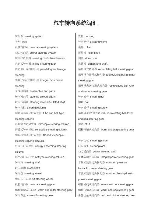
汽车转向系统词汇转向系steering system类型type机械转向系manual steering system动力转向系power steering system转向操纵机构steering control mechanism直列式转向器in-line steering gear四边联杆式转向机构parallelogram linkage steering整体式动力转向机构integral type power steering总成和部件assemblies and parts转向万向节steering universal joint转向传动轴steering inner articulated shaft转向管柱steering column球轴承套管式转向管柱tube and ball type steering column可伸缩式转向管柱telescopic steering column折叠式转向管柱collapsible steering column倾斜和缩进式转向管柱tilt and telescopic steering column 吸能式转向管柱energy-absorbing steering column网络状转向柱管net type steering column转向轴steering shaft转向横轴cross shaft转向盘steering wheel倾斜式方向盘tilt steering wheel机构转向器manual steering gear蜗杆滚轮式转向器worm and roller steering gear 转向器盖 cover of steering gear 壳体housing转向蜗杆steering worm滚轮roller滚轮轴roller shaft侧盖side cover摇臂轴pitman arm shaft循环球式转向器recirculating ball steering gear 循环球和螺母式转向器recirculating ball and nut steering gear循环球齿条齿扇式转向器recirculating ball-rack and sector steering gear转向螺母steering nut钢球ball转向螺杆steering screw循环球-曲柄销式转向器recirculating ball-lever and peg steering gear指销stud蜗杆指销式转向器worm and peg steering gear转向齿轮steering pinion转向齿条steering rack动力转向器power steering gear整体式动力转向器integral power steering gear 常压式液压动力转向器constant pressure hydraulic power steering gear常流式液压动力转向器constant flow hydraulic power steering gear螺杆螺线式转向器screw and nut steering gear 蜗杆指销式转向器worm and peg steering gear 齿轮齿条式转向器rack and pinion steering gear变传动比转向器steering gear with variable ratio 转向控制阀steering control valve滑阀式转向控制器spool valve type阀体valve housing滑阀valve spool转阀式转向控制阀rotary valve type扭杆torsion bar转向动力缸power cylinder转向油泵power steering pump转向油罐oil reservoir转向传动杆系steering linkage动力转向系布置power steering system layout 反作用阀reactive valve梯形转向机构Ackerman steering整体式转向梯形杆系Ackerman steering linkages分段式转向梯形杆系divided Ackerman steering linkage中间转向杆intermediate steering rod转向摇臂pitman arm转向直拉杆steering drag link中间转向联杆center steering linkages端部螺塞end plug球头销ball stud球头座ball cup压缩弹簧compression spring梯形机构tie rod linkage梯形臂tie rod arm转向横拉杆steering tie rod接头socket横拉杆端接头tie rod end 分段式梯形机构split tie rod type tie rod linkage 摆臂swing arm动力转向power steering气压式动力转向air-power steering液压式动力转向hydraulic power steering液压常流式动力转向hydraulic constant flow type power steering液压储能式动力转向hydraulic accumulator power steering慢速转向slow steering快速转向fast steering (quick steering)过度转向oversteering转向不足understeering转向系刚度steering system stiffness方向盘自由行程free play of steering wheel转向器转动力矩rotating torque of steering gear 转向力矩steering moment转向阻力矩steering resisting torque转向力steering force转向传动比steering gear ratio (steering ratio0 恒定转向传动比constant ratio steering可变转向传动比variable ratio steering转向系角传动比steering system angle ratio转向器角传动比steering gear angle ratio转向传动机构角传动比steering linkage angle ratio转向器传动效率steering gear efficiency正效率forward efficiency逆效率reverse efficiency转向器扭转刚度torsional stiffness of steering gear转向盘总圈数total number of steering wheelturns转向器总圈数total turns of steering gear转向器传动间隙steering gear clearance摇臂轴最大转角max. rotating angle of pitman arm shaft转向摇臂最大摆角max. Swing angle of steering pitman arm转向器反驱动力矩reverse rotating torque of steering gear转向器最大输出扭矩steering gear max. Output torque最大工作压力max. Working pressure额定工作压力rated working pressure转向油泵理论排量theoretical displacement of pump限制流量limited flow转向控制阀预开隙pre-opened play of steering control valve转向控制阀全开隙totally -opened play of steering control valve转向控制阀内泄漏量internal leakage in steering control valve转向控制阀压力降pressure loss in steering control valve转向器角传动比特性steering gear angle ratio characteristic转向器传动间隙特性steering gear clearance characteristic转向器传动效率特性steering gear efficiency characteristic转向力特性steering force characteristic 动力转向系灵敏度特性power steering system response characteristic转向控制阀压力降特性steering control valve pressure loss characteristic前桥front axle工字梁I-beam双工字梁twin I-beam非驱动桥dead axle转向节steering knuckle挂车转向装置steering system of trailer中央主销式转向装置central king pin type steering system无主销转向装置no king pin type steering system 全杆式转向装置all linkage type steering system 球销式转向节ball and socket steering knuckle 转向节止推轴承steering knuckle thrust bearing 前轮轴front wheel spindle转向盘轴steering spindle转向节轴knuckle spindle转向节臂steering knuckle arm(转向节)主销knuckle pin(King pin)反拳式前桥reverse elliott axle反拳式转向节reverse elliott steering knuckle叉式前桥elliott type axle叉式转向节elliott steering knuckle。
汽车电子动力转向系统中英文对照外文翻译文献

中英文对照外文翻译Electronic power steering systemWhat it isElectrically powered steering uses an electric motor to drive either the power steering hydraulic pump or the steering linkage directly. The power steering function is therefore independent of engine speed, resulting in significant energy savings.How it works :Conventional power steering systems use an engine accessory belt to drive the pump, providing pressurized fluid that operates a piston in the power steering gear or actuator to assist the driver.In electro-hydraulic steering, one electrically powered steering concept uses a high efficiency pump driven by an electric motor. Pump speed is regulated by an electric controller to vary pump pressure and flow, providing steering efforts tailoredfor different driving situations. The pump can be run at low speed or shut off to provide energy savings during straight ahead driving (which is most of the time in most world markets).Direct electric steering uses an electric motor attached to the steering rack via a gear mechanism (no pump or fluid). A variety of motor types and gear drives is possible. A microprocessor controls steering dynamics and driver effort. Inputs include vehicle speed and steering, wheel torque, angular position and turning rate.Working In Detail:A "steering sensor" is located on the input shaft where it enters thesensor" that converts steering torque input and its direction into voltage signals, and a "rotation sensor" that converts the rotation speed and direction into voltage signals. An "interface" circuit that shares the same housing converts the signals from the torque sensor and rotation sensor into signals the control electronics can process.Inputs from the steering sensor are digested by a microprocessor control unit that also monitors input from the vehicle's speed sensor. The sensor inputs are then compared to determine how much power assist is required according to a preprogrammed "force map" in the control unit's memory. The control unit then sends out the appropriate command to the "power unit" which then supplies the electric motor with current. The motor pushes the rack to the right or left depending on which way the voltage flows (reversing the current reverses the direction the motor spins). Increasing the current to the motor increases the amount of power assist.The system has three operating modes: a "normal" control mode in which left or right power assist is provided in response to input from the steering torque and rotation sensor's inputs; a "return" control mode which is used to assist steering return after completing a turn; and a "damper" control mode that changes with vehicle speed to improve road feel and dampen kickback.If the steering wheel is turned and held in the full-lock position and steering assist reaches a maximum, the control unit reduces current to the electric motor to prevent an overload situation that might damage the motor. The control unit is also designed to protect the motor against voltage surges from a faulty alternator or charging problem.The electronic steering control unit is capable of self-diagnosing faults by monitoring the system's inputs and outputs, and the driving current of the electric motor. If a problem occurs, the control unit turns the system off by actuating a fail-safe relay in the power unit. This eliminates all power assist, causing the system to revert back to manual steering. A dash EPS warning light is also illuminated to alert the driver. To diagnose the problem, a technician jumps the terminals on the service check connector and reads out the trouble codes.click here to see a biggerElectric power steering systems promise weight reduction, fuel savings and package flexibility, at no cost penalty.Europe's high fuel prices and smaller vehicles make a fertile testbed for electric steering, a technology that promises automakers weight savings and fuel economy gains. And in a short time, electric steering will make it to the U.S., too. "It's just just a matter of time," says Aly Badawy, director of research and development for Delphi Saginaw Steering Systems in Saginaw, Mich. "The issue was cost and that's behind us now. By 2002 here in the U.S. the cost of electric power steering will absolutely be a wash over hydraulic."Today, electric and hybrid-powered vehicles (EV), including Toyota's Prius and GM's EV-1, are the perfect domain for electric steering. But by 2010, a TRW Inc. internal study estimates that one out of every three cars produced in the world will be equipped with some form of electrically-assisted steering. The Cleveland-based supplier claims its new steering systems could improve fuel economy by up to 2 mpg, while enhancing handling. There are true bottom-line benefits as well for automakers by reducing overall costs and decreasing assembly time, since there's no need for pumps, hoses and fluids.Another claimed advantage is shortened development time. For instance, a Delphi group developed E-TUNE, a ride-and-handling software package that can be run off a laptop computer. "They can take that computer and plug it in, attach it to the controller and change all the handling parameters -- effort level, returnability, damping -- on the fly," Badawy says. "It used to take months." Delphi has one OEM customer that should start low-volume production in '99.Electric steering units are normally placed in one of three positions: column-drive, pinion-drive and rack-drive. Which system will become the norm is still unclear. Short term, OEMs will choose the steering system that is easiest to integrate into an existing platform. Obviously, greater potential comes from designing the system into an all-new platform."We have all three designs under consideration," says Dr. Herman Strecker, group vice president of steering systems division at ZF in Schwaebisch Gmuend, Germany. "It's up to the market and OEMs which version finally will be used and manufactured.""The large manufacturers have all grabbed hold of what they consider a core technology," explains James Handysides, TRW vice president, electrically assisted steering in Sterling Heights, Mich. His company offers a portfolio of electric steering systems (hybrid electric, rack-, pinion-, and column-drive). TRW originally concentrated on what it still believes is the purest engineering solution for electric steering--the rack-drive system. The system is sometimes refered to as direct drive or ball/nut drive.Still, this winter TRW hedged its bet, forming a joint venture with LucasVarity. The British supplier received $50 million in exchange for its electric column-drive steering technology and as sets. Initial production of the column and pinion drive electric steering systems is expected to begin in Birmingham, England, in 2000."What we lack is the credibility in the steering market," says Brendan Conner, managing director, TRW/LucasVarity Electric Steering Ltd. "The combination with TRW provides us with a good opportunity for us to bridge that gap." LucasVarity currently has experimental systems on 11 different vehicle types, mostly European. TRW is currently supplying its EAS systems for Ford and Chrysler EVs in North America and for GM's new Opel Astra.In 1995, according to Delphi, traditional hydraulic power steering systems were on 7596 of all vehicles sold globally. That 37-million vehicle pool consumes about 10 million gallons in hydraulic fluid that could be superfluous, if electric steering really takes off.The present invention relates to an electrically powered drive mechamsm for providing powered assistance to a vehicle steering mechanism. According to one aspect of the present invention, there is provided an electrically powered driven mechanism for providing powered assistance to a vehicle steering mechanism having a manually rotatable member for operating the steering mechanism, the drive mechanism including a torque sensor operable to sense torque being manually applied to the rotatable member, an electrically powered drive motor drivingly connected to the rotatable member and a controller which is arranged to control the speed and direction of rotation of the drive motor in response to signals received from the torque sensor, the torque sensor including a sensor shaft adapted for connection to the rotatable member to form an extension thereof so that torque is transmitted throughsaid sensor shaft when the rotatable member is manually rotated and a strain gauge mounted on the sensor shaft for producing a signal indicative of the amount of torque being transmitted through said shaft.Preferably the sensor shaft is non-rotatably mounted at one axial end in a first coupling member and is non-rotatably mounted at its opposite axial end in a second coupling member, the first and second coupling members being inter-engaged to permit limited rotation therebetween so that torque under a predetermined limit is transmitted by the sensor shaft only and so that torque above said predetermined limit is transmitted through the first and second coupling members.The first and second coupling members are preferably arranged to act as a bridge for drivingly connecting first and second portions of the rotating member to one another.Preferably the sensor shaft is of generally rectangular cross-section throughout the majority of its length.Preferably the strain gauge includes one or more SAW resonators secured to the sensor shaft.Preferably the motor is drivingly connected to the rotatable member via a clutch.Preferably the motor includes a gear box and is concentrically arranged relative to the rotatable member.Various aspects of the present invention will hereafter be described, with reference to the accompanying drawings, in which :Figure 1 is a diagrammatic view of a vehicle steering mechanism including an electrically powered drive mechanism according to the present invention,Figure 2 is a flow diagram illustrating interaction between various components of the drive mechanism shown in Figure 1 ,Figure 3 is an axial section through the drive mechanism shown in Figure 1, Figure 4 is a sectional view taken along lines IV-IV in Figure 3,Figure 5 is a more detailed exploded view of the input drives coupling shown in Figure 3, andFigure 6 is a more detailed exploded view of the clutch showing in Figure 3. Referring initially to Figure 1 , there is shown a vehicle steering mechanism 10 drivingly connected to a pair of steerable road wheels The steering mechanism 10 shown includes a rack and pinion assembly 14 connected to the road wheels 12 via joints 15. The pinion(not shown) of assembly 14 is rotatably driven by a manually rotatable member in the form of a steering column 18 which is manually rotated by a steering wheel 19.The steering column 18 includes an electric powered drive mechanism 30 which includes an electric drive motor (not shown in Figure 1) for driving the pinion in response to torque loadings in the steering column 18 in order to provide power assistance for the operative when rotating the steering wheel 19.As schematically illustrated in Figure 2, the electric powered drive mechanism includes a torque sensor20 which measures the torque applied by the steering column 18 when driving the pinion and supplies a signal to a controller 40. The controller 40 is connected to a drive motor 50 and controls the electric current supplied to the motor 50 to control the amount of torque generated by the motor 50 and the direction of its rotation.The motor 50 is drivingly connected to the steering column 18 preferably via a gear box 60, preferably an epicyclic gear box, and a clutch 70. The clutch 70 is preferably permanently engaged during normal operation and is operative under certain conditions to isolate drive from the motor 50 to enable the pinion to be driven manually through the drive mechanism 30. This is a safety feature to enable the mechanism to function in the event of the motor 50 attempting to drive the steering column too fast and/or in the wrong direction or in the case where themotor and/or gear box have seized.The torque sensor 20 is preferably an assembly including a short sensor shaft on which is mounted a strain gauge capable of accurately measuring strain in the sensor shaft brought about by the application of torque within a predetermined range.Preferably the predetermined range of torque which is measured is 0-lONm; more preferably is about l-5Nm.Preferably the range of measured torque corresponds to about 0-1000 microstrain and the construction of the sensor shaft is chosen such that a torque of 5Nm will result in a twist of less than 2° in the shaft, more preferably less than 1 °.Preferably the strain gauge is a SAW resonator, a suitable SAW resonator being described in WO91/13832. Preferably a configuration similar to that shown in Figure 3 of WO91/13832 is utilised wherein twoSAW resonators are arranged at 45° to the shaft axis and at 90° to one another.Preferably the resonators operate with a resonance frequency of between 200-400 MHz and are arranged to produce a signal to the controller 40 of 1 MHz ±500 KHz depending upon the direction of rotation of the sensor shaft. Thus, when the sensor shaft is not being twisted due to the absence of torque, it produces a 1 MHz signal.When the sensor shaft is twisted in one direction it produces a signal between 1.0 to 1.5 MHz. When the sensor shaft is twisted in the opposite direction it produces a signal between 1.0 to 0.5 MHz. Thus the same sensor is able to produce a signal indicative of the degree of torque and also the direction of rotation of the sensor shaft.Preferably the amount of torque generated by the motor in response to a measured torque of between 0-10Nm is 0-40Nm and for a measured torque of between l-5Nm is 0-25Nm.Preferably a feed back circuit is provided whereby the electric current being used by the motor is measured and compared by the controller 40 to ensure that the motor is running in the correct direction and providing the desired amount of power assistance. Preferably the controller acts to reduce the measured torque to zero and so controls the motor to increase its torque output to reduce the measured torque.A vehicle speed sensor (not shown) is preferably provided which sends a signal indicative of vehicle speed to the controller. The controller uses this signal to modify the degree of power assistance provided in response to the measured torque.Thus at low vehicle speeds maximum power assistance will be provided and a high vehicle speeds minimum power assistance will be provided.The controller is preferably a logic sequencer having a field programmable gate array for example a XC 4005 as supplied by Xilinx. Such a controller does not rely upon software and so is able to function more reliably in a car vehicle environment. It is envisaged that a logic sequence not having a field programmable array may be used.Electronic power steering system (English as EPS), and hydraulic power steering system (HPS) compared to, EPS has many advantages.The advantage is that the EPS:1) high efficiency. HPS efficiency is very low, generally 60% to 70%, while EPS and electrical connections, high efficiency, and some can be as high as 90 percent.2) less energy consumption. Automobile traffic in the actual process, at the time to about 5 percent of the time travelling, the HPS system, engine running, the pumps will always be in working condition, the oil pipeline has been in circulation, so thatvehicle fuel consumption rate by 4 % To 6%, while EPS only when needed for energy, vehicle fuel consumption rates only increased by 0.5 percent.3) "Road sense of" good. Because EPS internal use of rigid, system of the lag can be controlled by software, and can be used in accordance with the operation of the driver to adjust.4) back to being good. EPS simple structure of small internal resistance, is a good back, get back to being the best characteristics, improve vehicle handling and stability.5) little environmental pollution. HPS hydraulic circuit in the hydraulic hoses and connectors, the existence of oil leaking, but hydraulic hoses can not be recovered, the environmental pollution are to a certain extent, while EPS almost no pollution to the environment.6) can be independent of the engines work. EPS for battery powered devices, as long as sufficient battery power, no matter what the condition for the engine, can produce power role.7) should have a wide range.8) easy to assemble and good layout.Now, power steering systems of some cars have become the standard-setting, the whole world about half of the cars used to power steering. With the development of automotive electronics technology, some cars have been using electric power steering gear, the car of the economy, power and mobility has improved. Electric power steering device on the car is a new power steering system device, developed rapidly in recent years both at home and abroad, because of its use of programmable electronic control devices, the flexibility in the same time there are also potential safety problems. In the analysis This unique product on the basis of the author of the characteristics of electronic control devices, security clearance just that the factors that deal with security measures, and discussed a number of concerns the safety of specific issues. The results show that : Existing standards can not meet the electric power steering device security needs and made the electric power steering device safety evaluation of the idea. Research work on the electric power steering device development and evaluation of reference value.电子动力转向系统图1电子动力转向系统的工作原理电子动力转向系统是通过一个电动机来驱动动力方向盘液压泵或直接驱动转向联动装置。
重型卡车转向系统-中英文版-2015-11
5
转向液压原理 Steering hydraulic principle
右转方向 Right direction 当方向盘向右转动时,活塞将向右侧移动,在左侧动力腔内将 建立起一个转向所需的压力。 When the steering wheel is turned to the right, the piston will move to the right, and the pressure will be set up in the left power chamber. 转阀顺时针方向偏转,进油槽(K)的开度变大,允许油液进入。 同时,进油槽(J)关闭,以防油液进入到轴向槽(O)。 The turning valve is in a clockwise direction, and the opening of the radial groove (K) is large, allowing the oil to enter. At the same time, the radial groove (J) is closed to prevent oil from entering into the axial grooves (O). 此时油液将通过进油槽(K)进入阀套上的轴向槽(N),然后刘 静滚珠丝杆进入左侧的动力腔。进油槽(J)关闭,以防油液流回 油壶,在左侧动力腔内建立起压力。 At this point the oil will pass through the radial groove (K) into the valve sleeve on the axial grooves (N), and then Liu Jing ball screw into the left side of the power chamber. An radial groove (J) closed, to prevent the oil into the pot, set up the pressure in the left power cavity. 右侧动力腔中的油液将被排出,通过打开的回油槽(M)流入转 阀上的回油槽(P),然后通过转阀及蜗杆上的油孔流回到油壶。 Right power cavity in the oil will be discharged, through the open back to return oil control grooves (M) inflow valve on the back of return oil control grooves (P), then transferred through the oil hole in the valve and the worm flows back into the oil reservoir .
机动车转向系统外文原文及其翻译
本文摘于《Race Car Vehicle Dynamics》作者:William F. Miliken and Douglas L. MilikenSteering systemsIntroductionThis chapter begins with a discussion of steering geometry—casterangle ,trail ,kingpin inclination ,and scrub radius .The next section discuss Ackermann geometry followed by steering racks and gears .Ride steer (bump steer ) and roll steer are closely related to each other ;without compliance they would be thesame .Finally ,wheel alignment is discussed .this chapter is tied to chapter 17 on suspension geometry –when designing a new chassis ,steering and suspension geometry considerations are high priorities .19.1 steering geometryThe kingpin in a solid front axle is the steering pivot .In modern independent suspensions , introduced by Maurice olley at Cadillac in 1932,the kingpin is replaced by two (or more ) ball joints that define the steering axis .This axis is not vertical or centered on the tire contact patch for a number of reason .see figure 19.1 to clarify how kingpin location is measured .In front view ,the angle is called kingpin inclination and the offset of the steering axis from the center of the tire print measured along the ground is called scrub (or scrub radius ). The distance from the kingpin axis to the wheel center plane , measured horizontally at axle height ,is the spindle length .In side view the kingpin angle is called caster angle ; if the kingpin axis does not pass through the wheel center then side view kingpin offset is present ,as in most motorcycle front ends .The distance measured on the ground from the steering axis to the center of the tire print is the trail (called caster offset in ref .1 )Kingpin front view geometryAs mentioned in chapter 17, kingpin inclination ,spindle length ,and scrub are usually a compromise between packaging and performance requirements .Some factors to consider include :1.With a positive spindle length (virtually every car is positive as shown in figure 19.1) the car will be raised up as the wheels are steered away from center .The more the kingpin inclination is tilted from vertical the more the car will be raised when the front wheels are steered .This effect always raises the car , regardless of which direction the wheel is steered ,unless the kingpin inclination is truevertical .the effect is symmetric side to side only if there is no caster angle .See the following section on caster angle .For a given kingpin inclination ,a longer positive spindle length will increase the amount of lift with steer .2.The effect of kingpin inclination and spindle length in raising the front end ,by itself ,is to aid centering of the steering at low speed .At high speed any trail will probably swamp out the effect that raise ad fall have on centering .3. Kingpin inclination affects the steer –camber characteristic .when a wheel is steered ,it will lean out at the top ,toward positive camber ,if the kingpin is inclined in the normal direction (toward the center of the car at the upper end ). Positive camber results for both left– and right-hand steer .the amount of this effect is small ,but significant if the track includes tight turns.4. When a wheel is rolling over a bumpy road ,the rolling radius is constantly changing ,resulting in changes of wheel rotation speed . This gives rise to longitudinal forces at the wheel center .The reaction of these forces will introduce kickback into the steering in proportion to the spindle length .If the spindle length is zero then there will be no kick from this source .Design changes made in the last model of the GM “P ”car (fiero ) shortened the spindle length and this resulted in less wheel kickback on rough roads when compared to early model “P ”cars.5. The scrub radius shown in figure 19.1 is negative ,as used on front-wheel–drive cars (see below ) . driving or braking forces (at the ground ) introduce steer torques proportional to the scrub radius . If the driving or braking force is different on left and right wheels then there will be a net steering torque felt by the driver (assuming that the steering gear has good enough rev erse efficiency ).The only time that this is not true is with zero scrub (centerpoint steering ) because there is no moment arm for the drive (or brake ) force to generate torque about the kingpin .With very wide tires the tire forces often are not centered in the wheel center plane due to slight changes in camber ,road surface irregularities ,tire nonuniformity (conicity ),or other asymmetric effects .These asymmetries can cause steering kickback regardless of the front view geometry .Packaging requirements often conflict with centerpoint steering and many race cars operate more or less okay on smooth tracks with large amounts of scrub .6. For front drive ,a negative scrub radius has two strong stabilizingeffects :first ,fixed steering wheel –if one drive wheel loses traction ,the opposingwheel will toe –out an amount determined by the steer compliance in the system .This will tend to steer the car in a straight line ,even though the tractive force is not equal side-to –side and the unequal tractive force is applying a yaw moment to the vehicle .Second ,with good reverse efficiency the driver’s hands never truly fix the steering wheel . In this case the steering wheel may be turned by the effect of uneven longitudinal tractive forces ,increasing the stabilizing effect of the negative scrub radius .Under braking the same is true .Negative scrub radius tends to keep the car traveling straight even when the braking force is not equal on the left and right side front tiresome (due to differences in the roadway or the brakes).Caster angle and trailWith mechanical trail ,shown in figure 19.1,the tire print follows behind the steering axis in side view .Perhaps the simplest example is on an office chair caster–with any distance of travel ,the wheel aligns itself behind the point .More trail means that the tire side force has a large moment arm to act on the kingpin axis .This produces more self-centering effect and is the primary source of self-centering moment about the kingpin axis at speed .Some considerations for choosing the caster angle and trail are :1.More trail will give higher steering force .with all cars ,less trail will lower the steering force .In some cases ,manual steering can be used on heavy sedans (instead of power steering ) if the trail is reduced to almost zero .2.Caster angle ,like kingpin inclination ,cause the wheel to rise and fall with steer .unlike kingpin inclination ,the effect is opposite from side to side .With symmetric geometry (including equal positive caster on left and right wheels ) ,the effect of left steer is to roll the car to the right ,causing a diagonal weight shift .In this case ,more load will be carried on the LF –RR diagonal ,an oversteer effect in aleft-hand turn .The diagonal weight shift will be larger if stiffer springing is used because this is a geometric effect .The distance each wheel rises (or falls ) is constant but the weight jacking and chassis roll angle are functions of the front and rear roll stiffness. This diagonal load change can be measured with the car on scales and alignment ( weaver ) plates .Keep in mind that the front wheels are not steered very much in actual racing , except on the very tightest hairpin turns . For example , on a 100-ft .radius (a 40-50 mph turn ), a 10-ft. wheelbase neutral steer car needs only about 0.1rad .(5.7)of steer at the front wheels (with a 16:1steering ratio this is about 90degree at the steering wheel ).For cars that turn in one direction only , caster stagger (differences in left and right caster ) is used to cause the car to pull to one side due to the car seeking the lowest ride height . caster stagger will also affect the diagonal weight jacking effect mentioned above .If the caster is opposite (positive on one side and negative the same number of degrees on the other side ) then the front of the car will only rise and fall with steer ,no diagonal weight jacking will occur .3. Caster angle affects steer-camber but ,unlike kingpin inclination ,the effect is favorable . With positive caster angle the outside wheel will camber in a negative direction (top of the wheel toward the center of the car ) while the inside wheel cambers in a positive direction , again learning into the turn .In skid recovery , “opposite lock ” (steer out of the turn ) is used and in this case the steer–camber resulting from caster angle is in the “wrong ” direction for increased front tire grip . conveniently ,this condition results from very low lateral force at the rear so large amounts of front grip are not needed .4. As discussed in chapter 2, tires have pneumatic trail which effectively adds to (and at high slip Angles subtracts from ) the mechanical trail . This tire effect is nonlinear with lateral force and affects steering torque and driver feel .In particular , the fact that pneumatic trail approaches zero as the tire reaches the limit will result in lowering the self-centering torque and can be s signal to the driver that the tire is near breakaway .The pneumatic trail “breakaway signal” will be swamped out by mechanical trail if the mechanical trail is large compared to the pneumatic trail .5.Sometimes the trail is measured in a direction perpendicular to the steering axis (rather than horizontal as shown in figure 19.1) because this more accurately describes the lever (moment ) arm that connects the tire lateral forces to the kingpin . Tie rod locationNote that in figure 19.1 a shaded area is shown for the steering tie rod location . Camber compliance under lateral force is unavoidable and if the tie rod is located as noted ,the effect on the steering will be in the understeer ( steer out of the turn ) direction becomes much more complex than can be covered here .19.2 Ackerman steering geometryAs the front wheels of a vehicle are steered away from the straight-ahead position ,the design of the steering linkage will determine if the wheels stay parallel or if one wheel steers more than the other .This difference in steer Angles on the left and right wheels should not be confused with toe-in or toe-out which are adjustments and add to ( or subtract from ) Ackerman geometric effects .For low lateral acceleration usage (street cars) it is common to use Ackerman geometry . as seen on the left of figure 19.2, this geometry ensures that all the wheels roll freely with no slip Angles because the wheels are steered to track a common turn center . Note that at low speed all wheels are on a significantly different radius , the inside front wheel must steer more than the outer front wheel . A reasonable approximation to this geometry may be as shown in figure 19.3.According to ref .99, Rudolf Ackerman patented the double pivot steering system in 1817 and in 1878, Charles Jeantaud added the concept mentioned above to eliminate wheel scrubbing when cornering . Another reason for Ackermann geometry ,mentioned by Maurice olley , was to keep carriage wheels from upsetting smooth gravel driveways .High lateral accelerations change the picture considerably . Now the tires alloperate at significant slip Angles and the loads on the inside track are less than on the outside track . Looking back to the tire performance curves ,it is seen that less slip angle is required at lighter loads to reach the peak of the cornering force to a higher slip angle than required for maximum side force . Dragging the inside tire along at high slip Angles ( above for peak lateral force ) raise the tire temperature and slows the car down due to slip angle ( induced ) drag .For racing , it is common to use parallel steering or even reverse Ackermann as shown on the center and right side of figure 19.2.It is possible to calculate the correct amount of reverse Ackermann if the tire properties and loads are known . In most cases the resulting geometry is found to be too extreme because the car must also be driven (or pushed ) at low speeds , for example in the pits .Another point to remember is that most turns in racing have a fairly large radius and the Ackermann effect is very small . In fact , unless the steering system and suspension are very stiff ,compliance (deflection ) under cornering loads may steer the wheels more than any Ackermann (or reverse Ackermann ) built into the geometry .The simplest construction that generates Ackermannn geometry is shown in figure 19.3 fo r “rear steer ” . Here ,the rack (cross link or relay rod in steering box systems ) is located behind the front axle and lines staring at the kingpin axis , extended through the outer tie rod ends , intersect in the center of the rear axle . The angularity of the steering knuckle will cause the inner wheel to steer more than the outer (toe-out on turning ) and a good approximation of “perfect Ackermann ” will be achieved .The second way to design-in differences between inner and outer steer Angles is by moving the rack (or cross link ) forward or backward so that it is no longer on a line directly connecting the two outer tie rod ball joints .This is shown in figure 19.4. with “rear steer ” , as shown in the figure ,moving the rack forward will tend mo re toward parallel steer (and eventually reverse Ackermann ), and moving it toward the rear of the car will increase the toe-out on turning .A third way to generate toe with steering is simply to make the steering arms different lengths . A shorter steering arm (as measured from the kingpin axis to the outer tie rod end ) will be steered through a larger angle than one with a longer knuckle. Of course this effect is asymmetric and applies only to cars turning in one direction—oval track cars .RecommendationWith the conflicting requirements mentioned above , the authors feel that parallel steer or a bit of reverse Ackermann is a reasonable compromise . With parallel steer , the car will be somewhat difficult to push through the pits because the front wheels will be fighting each other . at racing speeds , on large-radius turns , the front wheels are steered very little , thus any ackermann effects will not have a large effect on the individual wheel slip angles , relative to a reference steer angle , measured at the centerline of the car .文献翻译摘自《Race Car Vehicle Dynamics》第19章转向系统序言:本章以转向几何参数的讨论为开始,包括主销后倾角,后倾拖距,主销内倾角,主销偏置量。
汽车专业英语术语汇总(复习资料)
UNIT 1 AUTOMOTIVE BASICS Body:车身chassis:底盘stream-lined:流线wind resistance:风阻Frame:车架the power train:传动系统the drive train:驱动系a unitized body:承载式车身unibody:整体式汽车车身suspension system:悬架系统steering system:转向系统braking system(制动系统) suspension system:悬架系统shock absorber:减振器control arm:控制臂、导向机构steering gears:转向器steering wheel:转向盘idler arm:随动臂tie rods:横拉杆power steering:动力转向Power booster:助力器master cylinder:制动主缸Disc brake:盘式制动drum brake:鼓式制动Brake pedal:制动踏板brake system:制动系统stopping power:制动力Hydraulic brakes:液压制动brake pedal:制动踏板brake fluid:制动液brake lines:制动管路cylinders:轮缸brake shoes:制动蹄drum:制动鼓disc brake:盘式制动器pliers:老虎钳squeeze:挤进,握紧;夹紧rotating disc:旋转制动盘Drum brake:鼓式制动器gasoline-burning piston engine:活塞式汽油发动机Diesel-fuel burning engines:柴油发动机Fuel system:供给系统exhaust system:排气系统Cooling system:冷却系统lubrication system:润滑系统ignition system:点火系统electric spark:电火花air-fuel mixture:可燃混合气cylinder:汽缸ignition switch:点火开关current:电流storage battery:蓄电池ignition coil:点火线圈Distributor:分电器spark plug:火花塞compression ignition engines:压燃式发动机charging circuit:充电电路regulator:电压调节器alternator (or generator):发电机mechanical energy:机械能electrical energy:电能maximum voltage:最大电压fuel system:燃料供给系统fuel pump:燃油泵Filter:滤清器carburetor:化油器fuel injection system:燃油喷射系统combustible mixture:可燃混合气manifold:进气管exhaust system:排气系统carbon monoxide:一氧化碳hydrocarbons(碳氢化合物)oxides of nitrogen:氮氧化合物emission control system:排放控制系统cooling system:冷却系统combustion chamber:燃烧室coolant:冷却液Radiator:散热器water pump:水泵hollow:空的、空洞的block:汽缸体head:汽缸盖Defroster:(除冰(或霜)装置) Lubrication system润滑系统lubricant:润滑剂piston rings:活塞环cylinder walls:汽缸壁oil filter:机油滤清器Transmission:变速器wheel bearings:车轮轴承differential:差速器steering linkage:转向链接机构power train:传动系统transmission:变速器shift lever:变速杆clutch:离合器Transmission:变速器torque:转矩Differential:差速器drive /propeller shaft:传动轴universal joints:万向节axle movement:轴向运动flexible universal joints:活动万向节Differential:差速器UNIT 2 AUTOMOTIVE ENGINEinternal combustion engine:内燃机liquefied petroleum gas(LPG):液化石油气Compressed natural gas(CNG):压缩天然气drive shaft:驱动轴rear-wheel-drive arrangement:后轮驱动布置形式front-wheel-drive arrangement:前轮驱动布置形式drive wheels:驱动轮mid-engine arrangement:发动机中置Pistons:活塞reciprocate:往复spark ignition engine:火花点燃式发动机compression ignition(CI) engine:压燃式发动机electric ignition system:电子点火系统spark plug:火花塞ignite:点燃cylinders:气缸combustion:燃烧compression-ignition engine:压燃式发动机diesel engine:柴油机Spray:喷入heavy-duty trucks:重型货车spark-ignition engine:火花点燃式发动机fuel system:燃料供给系统ignition system:点火系统lubricating system:润滑系统cooling system:冷却系统fuel system:燃料供给系统combustible mixture:可燃混合物air/fuel mixture:空气燃料混合气ignition system:点火系统spark plug:火花塞air/fuel mixture:可燃混合气lubricating oil:润滑油lubricating system:润滑系统oil pump:机油泵reservoir:贮存器; 油箱exhaust gas:排气cooling system:冷却系统exhaust system:排气系统emission-control system:排放控制系统starting system:启动系统Crank:转动曲柄starting motor:启动马达internal combustion engine:内燃机chemical energy:化学能heat energy:热能mechanical energy:机械能air/fuel ratio:空燃比Diesel engines:柴油机intake:进气connecting rod:连杆crankshaft:曲轴reciprocating movement/back and forth movement/up and down movement(往复运动) rotary motion/ turning motion:(旋转运动) crankshaft:曲轴Efficiency:效率potential energy:潜能mechanical energy:机械能overall efficiency:总效率compression ratio:压缩比air/fuel ratio:空燃比uppermost position/(TDC, top dead center:上止点lowest position/BDC, bottom dead center:下止点stroke:行程four stroke-cycle Gasoline Engine: intake stroke:进气行程compression stroke:压缩行程power stroke:作功行程exhaust stroke:排气行程revolution:转、圈connecting rod:连杆intake valve:进气门camshaft:凸轮轴pressure difference:压力差air/fuel mixture:空气/燃料混合气compression ratio:压缩比TDC:上止点exhaust valve:排气门exhaust gases:废气starter motor:启动马达ignition key:点火钥匙start position:启动位置Flywheel:飞轮UNIT 3 AUTOMOTIVE LUBRICATION SYSTEM (汽车润滑系统) 3.1 Lubrication Principles 润滑原理Friction:摩擦primary job:基本任务Residual oil:残留的机油Lubricant:滑润剂hydrodynamic:液力的oil adhesion:机油粘度sliding friction:滑动摩擦Pressure-Lubrication System压力润滑系统oil pan:油底壳block:汽缸体oil pump:油泵drain plug:放油螺塞oil-pan gasket:油底壳垫圈Passageway:油道oil filter:机油滤清器Crankcase:曲轴箱tube:管filter screen:滤网gear-type:齿轮泵rotor-type:转子泵full-flow filtering system:全流式滤清器pressure-relief valve:安全阀bypass valve:旁通阀camshaft(凸轮轴)main bearing:主轴承camshaft bearing:凸轮轴轴承Foam inhibitor:泡沫抑制剂UNIT 4 THE COOLING SYSTEM(冷却系统) exhaust system:排气系统cylinder wall:汽缸壁piston:活塞cylinder head:汽缸盖oil film:油膜fuel mileage:燃油经济性exhaust emissions:废气排放liquid cooling:水冷air cooling:风冷water jacket:水套thermostat:节温器water pump:水泵radiator:散热器radiator cap:散热器盖cooling fan:冷却风扇hoses:软管expansion tank:膨胀水箱overflow tank:溢流水箱4.1 Water Pump(水泵)centrifugal pump:离心泵centrifugal force:离心力4.2 Water Jacket(水套)hot spot:热点valve seat:气门座valve guide:气门导管cylinder wall:汽缸壁combustion chamber:燃烧室4.3 Radiator(散热器)heat exchanger:热交换器4.4 Pressure Cap(散热器盖)boiling point:沸点pressure release valve:减压阀, 安全阀overflow tube:溢流管overflow tank:溢流箱4.5 Thermostat(节温器)4.6 Fancooling fan:冷却风扇constant temperature:常温thermostatic switch:温控开关UNIT 5 FUEL INJECTION SYSTEMFuel injection system:燃油喷射系统purely mechanical:纯机械的electronic fuel injection system:电子燃油喷射系统feedback control:反馈控制emission:排放solenoid valve:电磁阀injector:喷油器best power:最佳动力性best emission:最佳排放性best economy:最佳经济性rich condition:浓(混合气)工况lean condition:稀(混合气)工况5.3 Fuel System(燃油系统)fuel rail:油轨regulator:压力调节器return line:回油管fuel manifold:燃油歧管intake manifold:进气歧管5.4 Air Metering and Measurement 空气计量butterfly valve:传统碟形阀throttle body assembly:节气门体总成Mass Airflow:质量流量Speed Density:速度密度spring loaded flap:翼片potentiometer:电位计heated wire:加热电阻丝voltage signal:电压信号5.5 Most EFI systems measure the same basic 6 input 大多数EFI系统检测6个基本输入(信号)RPM(转速)ignition coil:点火线圈magnetic sensor:磁脉冲传感器Hall effect sensor:霍尔效应传感器Manifold Pressure (进气歧管压力)Throttle Position (节气门位置)Water Temperatureinjector pulse width:喷油器脉冲宽度Air Temperature5.6 Oxygen Sensor(氧传感器)closed loop systems:闭环系统oxygen content:氧含量air/fuel ratio:空燃比open loop mode:开环模式UNIT 6 EXHAUST SYSTEMexhaust system:排气系统Exhaust gas:废气combustion chamber:燃烧室muffler:消声器catalytic converter:催化转换器6.2 The Muffler(消声器)backpressure:背压exhaust valve:排气门6.3 The Exhaust Manifold and Headerexhaust manifold:排气歧管cylinder head:气缸盖intake manifold:进气歧管UNIT 7 THE IGNITION SYSTEM(点火系统) breaker point type ignition system:触点型点火系统electronic ignition system:电子点火系统distributorless ignition system: 无分电器点火系统)timing of the spark plug firing: 火花塞点火次序spark plug gap:火花塞间隙7.1 Point-Type Ignition System (触点型点火系统)electrical circuit:电路primary circuit:初级回路secondary circuit:次级回路breaker point:触点ignition switch:点火开关secondary winding:次级线圈high-tension lead:高压导线distributor:分电器coil:点火线圈distributor cap:分电器盖distributor rotor:分火头controlling element:控制元件primary current:初级电流Distributor:配电器7.2 Electronic Ignition Systems(电子点火系统)electronic control module:电子控制模块7.3 Distributorless Ignition Systems (DIS) (无分电器点火系统)spark timing:点火正时Ignition Control Unit (ICU):点火控制单元Engine Control Unit (ECU):发动机控制单元firing order:点火顺序Top Dead Center (TDC):上止点UNIT 8 CLUTCHdrive line/drive train:传动系统Clutch:离合器transmission:变速器drive shaft:传动轴final drive assembly:主减速器总成clutch disc:离合器片pressure plate:压盘pressure plate cover:离合器盖friction mechanism:摩擦机构engine torque:发动机扭矩gear ratio:传动比clutch pedal:离合器踏板driven member:从动件transmission input shaft:变速器输入轴driving members:主动件crankshaft:曲轴torsional shock:扭转振动starter motor:启动马达splined hub:花键毂spline:花键diaphragm spring:膜片弹簧centrifugal force:离心力release bearing:分离轴承disengagement mechanism:分离机构hydraulic system:液压系统hydraulic mechanism:液压机构clutch master cylinder:离合器主缸hydraulic fluid:制动液clutch release cylinder:离合器分离缸UNIT 9 AUTOMATIC TRANSMISSION(自动变速器)fluid coupling(液力偶合器)torque converter(变矩器rear wheel drive(后轮驱动)front wheel drive(前轮驱动).drive shaft(驱动轴)final drive(主减速器)rear axle(后轴)rear wheels(后轮)transaxle(驱动桥)Front axles(前桥)planetary gear sets(行星齿轮组) 9.1hydraulic system(液力系统)9.2Planetary gear sets(行星齿轮组)sun gear(太阳轮)ring gear(齿圈)planet gears(行星轮)constant mesh(常啮合common carrier(行星架)input shaft(输入轴)output shaft(输出轴)9.2 Clutch pack(离合器组)clutch drum(离合器鼓)friction material(摩擦材料)9.3 One-Way Clutch(单向离合器)"sprag" clutch(超越离合器)neutral(空挡)9.4 Bands(制动带)9.5 Torque Converter(液力变矩器)(见阅读材料)Torque Converter(液力变矩器)manual transmission:自动变速器automatic transmission:自动变速器brake pedal:制动踏板gas pedal:加速踏板1. Pump(泵轮).2. Turbine(涡轮).3. Stator(导轮).4. Transmission fluid(传动液). Freewheel:自由轮lockup clutch:锁止离合器UNIT 10 THE DIFFERENTIAL(差速器) unlimited-slip, differential:不防滑差速器10.1 The Main Gears(主减速器)bevel gear:锥齿轮axle shaft:半轴final drive assembly:主减速器总成gear reduction:减速drive wheel:驱动轮drive shaft:传动轴spiral bevel gear:螺旋锥齿轮center line(centerline):中心线10.2 The Differential System(差速系统) axle shaft:半轴side gear:半轴齿轮UNIT 11 BRAKE SYSTEM(制动系统) kinetic energy:惯性能量momentum:动量thermal energy (heat):热能master cylinder:主缸brake pedal:制动踏板mechanical pressure:机械压力hydraulic pressure:液体压力brake line:制动管brake hose:制动软管slave cylinder:轮缸Brake fluid:制动液Shoe:制动蹄pad:制动块drums:制动鼓rotor:制动盘disk brake:盘式制动器drum brakes:鼓式制动器caliper:制动嵌brake shoe:制动蹄friction lining:摩擦衬片friction surface:摩擦表面emergency brake:紧急制动Power brake booster:动力制动助力器master cylinder:制动主缸brake pedal:制动踏板hydraulic actuator:液压传动机构wheel speed sensor:车轮速度传感器UNIT 14 ABS AND TCS14.1 Braking System Fundamentals, master cylinder:主缸wheel cylinders:轮缸caliper pistons:制动钳活塞rolling energy:旋转能量14.2 Antilock Braking Systems(防抱死制动系统)retarding force:制动力percent slip滑移率braking effectiveness:制动效能wheel speed sensors (WSS):车轮速度传感器。
汽车转向控制中英文对照外文翻译文献
汽车转向控制中英文对照外文翻译文献(文档含英文原文和中文翻译)中英文对照翻译汽车的转向控制控制系统稳定性是针对提高驾驶安全性提出的一系列措施中最新的一个。
这个系统能够在40毫秒内实现从制动开始到制动恢复的过程,这个时间是人的反应时间得七倍。
他们通过调整汽车扭矩或者通过应用汽车左侧或右侧制动,如果需要甚至两者兼用,来实现准确的行车路线。
这个系统已被应用于奔驰S600汽车了。
稳定的机械自动系统能够在制动时发现肇端,并且在驾驶人员发现能够反应以前实现车辆的减速。
安全玻璃,安全带,撞击缓冲区,安全气囊,ABS系统,牵引力控制系统还有现在的稳定调节系统。
汽车安全系统的连续升级,已经产生了一种为保护汽车所有者安全的设计模式。
稳定调节系统帮助驾驶员从不可控制的曲线制动中解脱出来,从而避免了汽车的摆动滑行和交通事故。
利用计算机和一系列传感器,稳定调节系统能够检测到制动轮的打滑并且比人更快的恢复对汽车的方向控制。
系统每百万分之一秒作出一次快速捕捉,以及断断汽车是否在按照驾驶员的路线行驶。
如果检测到汽车行驶路线和驾驶员驾驶路线存在一个微小的偏差,系统会在瞬间纠正发动机扭矩或者应用汽车左右制动。
过程的标准反应时间是40毫秒----人的平均反应时间的七分之一。
罗伯特博世工程系统负责人安东·范·桑特解释说:“一个稳定的控制系统能够‘感觉到”驾驶员想要运动的方向,通过控制转向角度,油门踏板的位置,制动板的状态来确定汽车实际运动路线的偏航比率(汽车偏离方向轴的角度)和横向加速度”。
项目负责人阿明·马勒领导着范桑特的工作小组和奔驰汽车公司的工程师发明了第一个完全有效的稳定调节系统,该系统由发动机扭矩控制系统,制动系统,牵引控制系统组成以实现理想与现实运动之间的最小差距。
汽车安全专家相信稳定调节系统能够减少交通事故的发生,至少是在伤亡严重的事故方面。
安全统计表明,多数的单车撞击事故伤亡(占伤亡事故发生的4%),事故能够通过应用这项新技术避免。