单轨吊技术规格书驱样本
单轨吊设计资料
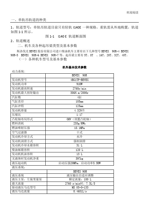
欢迎阅读一、单轨吊轨道的种类1、轨道型号:单轨吊轨道目前只有轻轨I140E一种规格,重轨需从外地购置,轨道如图1-1所示。
图1-1 I140 E 轨道断面图2、轨道概述二、机车及各种起吊梁类型及基本参数斯洛伐克BEVEX股份有限公司进口柴油机车主要有以下几种型号BEVEX 90R-4 BEVEX90R-5 BEVEX 90R-6 BEVEX 90R-7等,起吊梁主要有5T、8T 、16T、20T、32T、40T。
(一)各种机车型号及基本参数1、5吨起吊梁技术参数。
起吊重量5?000 kg起吊链条13 x 36T 8 DIN 5684 起吊高度3-6 m工作压强15 - 16 MPa工作介质46#抗磨液压油工作液压油流量90升/分钟运行轨道I 155 (I 140E)提升速度0.2 米/秒最大工作坡度±4°承受牵引力20kN2、8吨起吊梁技术参数起吊重量 2 x 4?000 kg起吊链条13 x 36T 8 DIN 5684 起吊高度3-6 m工作液压油流量30 升/分钟提升时间30秒工作液压油压强15 - 16 MPa工作介质46#抗磨液压油工作液压油流量30 升/分钟4、最大起吊重量 2 x 10?000 kg起吊链条13 x 39 DIN 5687最大起吊高度 1.64米工作液压油流量30升/分钟提升时间30 s最大工作压强16 + 10%MPa工作介质46#抗磨液压油最小工作液压油流量10 升/分钟运行轨道I 155 (I 140E)最小水平转弯半径 4 m最小垂直转弯半径8 m最大运行速度 2 m/s最大工作坡度± 30°最大承受牵引力120 kN5、32吨起吊梁技术参数起吊重量 2 x 16?000 kg起吊链条16 x 48 DIN 5687 最大起吊高度 1.64 米工作液压油流量30 升/分钟提升时间50 秒最大工作压强16 + 10%MPa 工作介质46#抗磨液压油最小工作液压油流量10 升/分钟运行轨道I 155 (I 140E)三、轨道的吊挂形式四、轨道锚固力的计算,与轨道的选型。
气动单轨吊车技术规格书
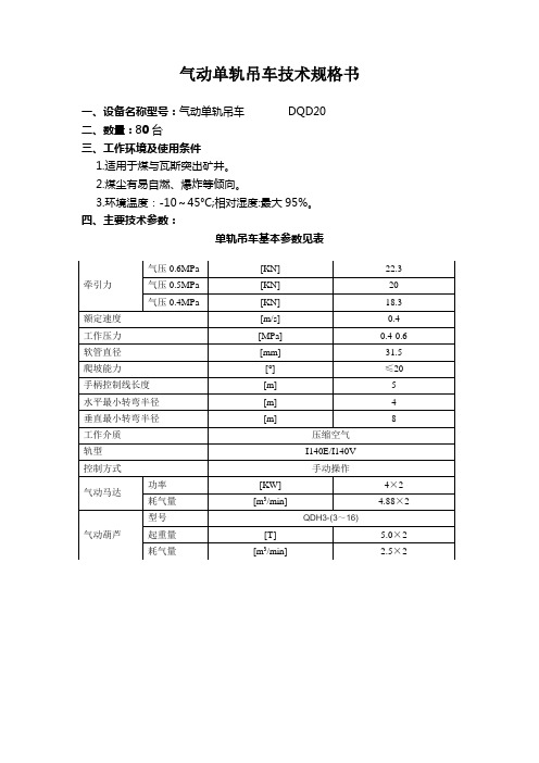
气动单轨吊车技术规格书一、设备名称型号:气动单轨吊车DQD20二、数量:80台三、工作环境及使用条件1.适用于煤与瓦斯突出矿井。
2.煤尘有易自燃、爆炸等倾向。
3.环境温度:-10~45°C;相对湿度:最大95%。
四、主要技术参数:单轨吊车基本参数见表六、技术要求1.设备符合最新版《煤矿安全规程》和国家下发的设备完好标准的相关要求。
2.设备风动葫芦及整机均需提供MA证。
3.风管进气口必须随机设有大的风源粗过滤器或风包,以便过滤压缩空气中的油污、水分和杂质,有利于液压元件的使用寿命。
4.单轨吊的液压制动系统必须灵敏可靠,在起吊重物行走时出现故障或“失压”时,能在原地(规定刹车距离)停车。
5.主机应配气喇叭,100米外应清晰听见鸣笛声;牵引箱合适处设置“紧急停车”按钮,紧急情况下能停止单轨吊运行。
6.为了确保设备使用安全,设备均采用双制动模式,即除设备主牵引装置内部马达转子或减速机构内部带一套制动装置外,再单独配一套独立的制动装置(制动方式为失效制动),两者总的制动力不低于40KN(牵引力的2倍)。
7.气控系统元件动作可靠,无渗漏且便于人工操作。
8.满足在±20°倾角的巷道内安全工作。
9.主机空气过滤器为不锈钢滤芯,具有自动清洗及排渣功能,无需人工清洗,便于维护,使用寿命不低于1年。
10.主润滑装置置于设备外侧,注油口为通用液压快接头形式,无需拆卸油杯。
11.主机应有防止润滑油雾随尾气扩散到空气中的大容量尾气吸油及消音装置。
12.主机驱动部分要带有超速保护功能,当设备运行速度超过1.2m/s时,设备应在无外界干预情况下自行可靠制动。
六、供货及服务要求:1.厂方设备必须提供设备整机的煤安标志证。
设备中所有需要煤安标志证的部件,必须具有有效的国家煤矿安全标志证书和“MA”标志。
2.设备交货时提供设备安装图份、使用说明书、产品合格证等证件六套,电子版说明书6套。
3.厂方免费提供设备安装指导、调试、操作技能培训及售后服务工作。
单轨吊专业技术规格书驱

14、安全保护形式: 过压保护、温度保护、超速保护等多种保护形式。
15、制动距离:最大制动距离≤4米,采用弹簧加压,液压释放形式,制动力≥415KN。
16、驾驶仓内应包含以下项目的预警和停机:
(1)柴油机冷却水温度;
(2)柴油机机油压力;
(3)柴油机机油温度;
(4)液压油温度;
六、供货范围
1、提供全部图纸、材料清单、所有设备、元件、部件型号、规格、特性参数表、产品检验合格证、MA标志证书、产品合格证,备品备件和易损件明细清单。
2、供货时应提供技术资料4套
(1)安装、操作、使用维修说明;
(2)全套的设备性能测试试验报告;
(3)所有图纸、说明书电子版一份,要求为PDF文档。
(4)配件图册电子版与纸质版各一份,纸质版要求对应的配件要有图文说明。
13、单轨吊机车具有机械超速保护功能和启动、停止,司机在操作室能够对其进行操作。
14、单轨吊机车驾驶室上下人梯,具有可伸缩性,能够满足高低巷道人员的上下,驾驶室座椅应配有随机保险带。
15、单轨吊机车的所有外露重要液压管路须加装保护套管,能够保护油管的磨损。
16、列出必须的易损件、专用工具与检测仪表的明细目录与价格。
4)轨道剖面: 140E/140V;
5)链条质量级别:8,校准链;
6)承载重量:不低于32000kg。
7)配备专用起吊横梁,起吊梁起吊链条的长度不低于10米。
5、机车配置风动加油机一套及测试工具一套。
七、免费提供随机配件
序号
名称
数量
单位
备注
1
起吊遥控器
1
件
2
气动加油机
1
台
气动单轨吊车使用说明书(30)

气动单轨吊车产品说明书(依据:Q/TSY010-2020)南京特斯元电子科技有限公司(2020年3月)目录DQDⅡY30型气动单轨吊车一、概述二、结构及功能说明三、产品新增功能四、DQD型气动单轨吊车技术参数表五、适用范围六、安装与调试七、使用、维护及警示八、常见故障与排除九、润滑要求十、易损件表DQDⅡY30型气动单轨吊车一、概述1、气动单轨吊车是煤矿井下短距离调度用起重运输设备之一。
它操作简便,自动化程度高,大大的降低了劳动强度,提高了生产效率,它可沿I140E/I140V轨前进、后退、转弯、爬坡、能随时停车,实现工作面的进入和退出功能可在水平、玩到、俯仰等多种复杂环境中自如工作。
2、型号说明:气动单轨吊车的型号及所表示的含义如下:D Q D ⅡY □最大牵引力,KN遥控功能改进型调度启动马达驱动单轨吊车二、结构及功能说明气动单轨吊车是以压缩空气为动力,推动气马达高速旋转,经变速<降低转速>增大了扭矩后带动驱动夹紧轮旋转,沿吊轨立面滚动,可随轨道水平。
转弯、上下俯仰进行。
它主要由停车制动装置、②联接体、③牵引装置(内含工作制动装置)、④手控阀、⑤气动葫芦、⑥滑车部件、⑦远程遥控等部分组成。
见图示<1>:图示<1>这七部分有序的巧妙构成,保证了产品安全有效的运行。
它们各自的功能是:①停车制动装置是气动单轨吊车运行中,除马达内部主刹车以外的一种补充刹车装置,单轨吊停止运行后,能使其保持静止状态的装置。
②联接体使保证牵引车、滑动小车、连杆的有效柔性联接关键部件;连杆是控制滑车、牵引车之间距离长短的联接件。
③牵引装置(内含工作制动装置)是拖动整个气动单轨吊车前后运行的动力机构。
④手控阀是实现牵引车机构前进、后退、刹车指令控制系统。
⑤滑车部件是挂载气动葫芦轨道运行的承载机构。
⑥启动葫芦是吊起重物的一种执行机构。
⑦远程遥控接收释放装置。
三、产品新增功能DQDⅡY25型气动单轨吊车可根据用户需求,新增以下功能:1、远程遥控(无线遥控)。
防爆柴油机单轨吊车技术规格书
防爆柴油机单轨吊车技术规格书一、招标设备:防爆柴油机单轨吊机车20套注:包含主机部分及起吊梁、平板车、集装箱等附属设备和设备采购金额3%的随机配件二、总体要求1.本规格书适用于XX矿业(集团)有限责任公司煤矿井下防爆柴油机单轨吊机车及附属设备的功能设计、结构、性能和安装等方面的技术要求。
2.本次招标防爆柴油机单轨吊机车要求投标厂家严格按照相关标准,确保设备安全运行。
要求整机噪音<85分贝,产品交付前必须有“煤矿矿用产品安全标志证书”。
3.投标厂家提供的产品符合国家级有关行业的技术标准,并且符合最新版的《煤矿安全规程》的要求。
本规格书提出的是最低限度的技术要求,并未对一切技术细节作出规定,也未充分引述有关标准和规范的条文,卖方应提供符合本规格书和所列标准要求的高质量产品及其相应服务。
对国家有关安全、环保等强制性标准,必须满足其要求。
4.如果卖方没有以书面形式对本规格书的条文提出异议,则意味着提供的设备完全符合本规格书的要求。
5.本技术规范书未尽事宜,由买、卖双方协商确定。
三、设备使用的条件运行环境:煤矿井下;环境温度:+10 ~+40℃;适应于具有瓦斯等爆炸气体的工作环境,具有防爆功能。
四、技术参数及要求(一)单轨吊机车1.控制方式:电液控制。
2.启动方式:液压启动。
3.起吊要求:液压起吊,电磁阀远方控制。
4.主机功率不小于130kW , 额定牵引力不小于160kN,驱动数量不少于8套。
5.主机工作寿命大于12000小时,主泵和液压马达工作寿命均不小于6000小时。
最大速度不小于2.6米/秒。
6.驱动轮:驱动轮寿命不小于1500小时,可根据需求调节驱动排列方式。
7.适应倾角:±25°,25°倾角巷道设备净运载能力不低于30t;25°倾角情况下配备的主机及起吊设备、人车能正常运行。
8.设备满足水平最小转弯半径4m、垂直最小转弯半径8m要求。
9.设备必须具备2路以上相对独立回油的制动系统,主机必须设置超速保护装置(机械和电气两种)。
单轨吊使用说明书分解
SDY-150型电缆拖挂单轨吊(华矿配200米)使用维护说明书安徽盛泰绝缘电气有限公司目录一、 SDY-150型电缆拖挂单轨吊的用途及特点二、 SDY-150型电缆拖挂单轨吊的主要技术参数三、 SDY-150型电缆拖挂单轨吊的主要结构及工作原理四、 SDY-150型电缆拖挂单轨吊的运输、安装和试运转五、 SDY-150型电缆拖挂单轨吊的操作与使用六、 SDY-150型电缆拖挂单轨吊操作注意事项七、 SDY-150型电缆拖挂单轨吊的维护与保养八、安全警告及配套件安全标志说明九、一般故障分析及处理十、 SDY-150型电缆拖挂单轨吊随机备件明细表十一、SDY-150型电缆拖挂单轨吊随机工具十二、随机备件、工具、技术文件目录十三、SDY-150型电缆拖挂单轨吊配件明细表十四、售后服务单一、DSY-150型电缆拖挂单轨吊的用途及特点在进行矿山井下作业时,大部分机械的电能是通过电缆传输的,随着机械的移位,电缆也要跟着移位,由于现在没有专用的井下巷道电缆拖运设备,电缆的拖运存在一定的困难。
例如,采煤机械在进行煤矿井下采煤时,随着采煤机械在工作面切割落煤,采煤面不断地向前推进,采煤机械也不断地向前推进,而动力电缆也必须跟着拖移,直到整个工作面的煤采完为止。
目前采煤工作面顺槽所有动力电缆的吊挂和拖运没有专用的吊挂和拖运机械设备,大多只是使用工字钢或槽钢焊接成简单的架子,悬挂在煤矿井下巷道内,动力电缆用铁丝捆绑在架子上,动力电缆的拖运靠人工或绞车,存在着动力电缆吊挂杂乱无章,拖运劳动强度大,作业不安全等缺点。
SDY-150电缆拖挂单轨吊(以下简称单轨吊)是用于煤矿井下综采工作面各种电缆高压胶管的吊挂、移动及回收的专用设备。
该设备利用锚杆和链条吊挂在综采工作面运输巷道一侧的顶板下,将井下工作面设备的动力电缆和高压胶管铺挂在一系列带滑轮的工作小车上,使用油缸与四连杆组成的液压步进式推拉装置,利用工作面现有的乳化液泵站作动力,操作液压控制阀手把,实现电缆沿着顺槽的吊挂和移动。
单轨吊技术要求

电机车单轨吊技术要求
一,1,DX80 型电机车单轨吊技术要求:
设备自重10.5t
定额载荷25t
总功率52kw
最大牵引力80kn
最大制动力≥120kn
最高速度1.6m/s
牵引速度0.5m/s
转弯曲率半径水平4m/垂直10m
外形尺寸18m×0.82m×1.3m
爬坡能力12°
2、配置设备(蓄电池,起吊梁,充电器}
爆蓄电池单轨吊2 台(各标配电池1 块,充电机1 台),6t 起吊梁6 台,20t 起吊梁2台,换电池车4 台,备用电池2 块。
3、轨道
轨道采用德国工业标准(DIN20593)的专用轨道I140E,采用标准直轨,每节3m,{2.25m} 宽68mm,高155mm,中板厚7mm;材料屈服应力 500MPa。
水平弯轨间及轨道与道岔连接处均采用专用法兰螺栓连接。
轨道的悬挂点由¢22×2500mm 双锚杆悬吊,单根锚杆锚固力不小于120kN,悬挂板由两锚杆固接后与链条销接,链条通过U 型环与轨道吊耳销接,确保轨道具有应有的承载能力。
4、如图示:
二、设备明细一览表
1、 DX80 单轨吊2台
2、备用电池2块(216V/560AH)
3、充电小车辆4
4、3m 单轨轨道1000根,2.25m 轨道100根 I140E
5、弯轨6套(5根/套)
6、气动道岔6副
7、6 T起吊梁6台
8、20T 起吊梁2台
9,悬挂板1000件
10、三环链1000件(18*64B)
11、U 型环件,1150套
12、吊环U2,1000个13、高强度螺丝M20*120*10.9。
LR 1160 轨道吊车机技术数据说明书
Complies with ANSI/ASME B 30.51003.03 Technical dataHydraulic lift craneLR 11602LR 1160 ANSI/ASME B 30.5DimensionsBasic machine with undercarriage5´4´´R19Remarks1. T he lifting capacitie s state d are valid for lifting ope ration only(corre sponding with crane classification according to F.E.M. 1.001. crane group A1).2. C rane standing on firm, horizontal ground.3. T he we ight of the lifting de vice (hoisting rope s, hook block, shackle etc.) must be deducted form the gross lifting capacity to obtain a net lifting value.4. A dditional equipment on boom (e.g. boom walkways, auxiliary jib) must be deducted to get the net lifting capacity.5. F or max. wind speed please refer to lift chart in operator‘s cab or manual.6. W orking radii are measured from center of swing and under load.7. T he lifting capacities are valid for 360 degrees of swing.8. C alculation of stability under load is based on ANSI/ASME B 30.5 load ratings as well as ISO 4305 Table 2 and is tested according to SAE J765.9. L oads for calculation of structure s are corre sponding to F.E.M. 1.001-1998 and are tested according to SAE J987.LR 1160 ANSI/ASME B 30.53Transport dimensions and weightsBasic machine and main boom (No. 2018.xx)Basic machinewith A-frame, 2x 26,780 lbf crane winches without boom foot, hoist ropes, basic counterweight and crawlers Width 9´10´´ We ight 77,160 lbs Weight of hoist rope 2.28 lbs/ftCrawler2 xTrack pads 39.4 inch Width 46.5 inch We ight38,055 lbsBoom section (No. 2018.20)10 ftWidth7´ Weight with HPT 1)1,500 lbs Weight with HPT 1) and NDL 2)1,655 lbsBoom section (No. 2018.20)20 ftWidth7´ Weight with HPT 1)2,185 lbs Weight with HPT 1) and NDL 2)2,425 lbsBoom section (No. 2018.20)38 ftWidth7´ Weight with HPT 1)5,480 lbs Weight with HPT 1) and NDL 2)4,190 lbsBoom head (No. 2018.20)Width7´ Weight with HPT 1) 6,400 lbsBoom transport option38 ft boom - and 38 ft jib extension 20 ft boom - and 20 ft jib extension (No. 2018.xx/1309.xx) 20 ft/20 ft 38 ft/38 ft Le ngth 20´2´´ 38´11´´Weight*3,575 lbs 6,305 lbsBoom foot (No. 2018.23)Width 7´Weight without winch 6,600 lbs W e ight incl. winch and rope10,050 lbs ¬0ENDANT¬STRAPS¬FOR¬MAIN¬BOOM¬¬s¬¬ ¬0ENDANT¬STRAPS¬FOR¬JIB*) Including pendant straps4LR 1160 ANSI/ASME B 30.5Transport dimensions and weightsLuffing jib (No. 1309.xx)Luffing jib head (No. 1309.22)Width 54.7 inch We ight* 3,530 lbsBoom section tapered (No. 2018/1309.20) 23.6 ftWidth 7´ We ight*2,340 lbs*) Including pendant straps22´10´´Luffing jib section (No. 1309.20)10 ftWidth 54.7 inch We ight*926 lbsLuffing jib section (No. 1309.20)20 ftWidth 54.7 inch We ight*1,150 lbsLuffing jib section (No. 1309.20)38 ftWidth 54.7 inch We ight*2,120 lbsLuffing jib foot with A-frames (No. 1309.22)Width 5´7´´ We ight*9,810 lbsFixed jib (No. 0806.xx)Fixed jib head (No. 0806.16)Width 37.4 inch We ight* 1,015 lbsFixed jib section (No. 0806.15)10 ftWidth 37.4 inch We ight*320 lbsFixed jib foot with A-frame (No. 0806.16)Width 7´3´´ We ight*2,295 lbsFixed jib section (No. 0806.15)20 ftWidth 37.4 i nch We ight*550 lbs5Transport dimensions and weightsLuffing jib (No. 1713.xx)Luffing jib head (No. 1713.21)Width 6´We ight* 3,035 lbsL-boom jib section (No. 1713.22)39.4 inchWidth 6´We ight* 870 lbsLuffing jib section (No. 1713.18)20 ftWidth 6´We ight* 1,390 lbsLuffing jib section (No. 1713.18)40 ftWidth 6´We ight* 2,515 lbs*) Including pendant straps Luffing jib foot with A-frames (No. 1713.22)Width 6´ We ight* 10,185 lbs Luffing jib section (No. 1713.18)10 ftWidth 6´ We ight* 950 lbs Boom section tapered (No. 1713.22)40 ftWidth 7´ We ight* 3,285 lbsFixed jib (No. 1008.xx)21´4´´Fixed jib head (No. 1008.20)Width 43 inch We ight* 2,030 lbsFixed jib section (No. 1008.17)10 ft Width 43 inch We ight* 660 lbsFixed jib foot with A-frame (No. 1008.20) Width 7´3´´ We ight* 4,300 lbs Fixed jib section (No. 1008.17)20 ft Width 43 inch We ight* 1,005 lbsLR 1160 ANSI/ASME B 30.56LR 1160 ANSI/ASME B 30.5Transport dimensions and weightsCounterweightCounterweight1 xWidth 53.5 inch We ight26,455 lbsCarbody counterweight2 xWidth 9´11´´ We ight22,050 lbs220,500 lbs hook block – 5 sheavesWidth 21.3 inch 25.2 inch 27.6 inch Weight2,870 lbs 3,970 lbs 5,070 lbs352,800 lbs hook block – 7 sheavesWidth 25.2 inch 29.9 inch 34.6 inch Weight 3,307 lbs 4,960 lbs 6,614 lbsHooks176,400 lbs hook block – 3 sheavesWidth 14.2 inch 18.1 inch 22.1 inch Weight2,205 lbs 3,310 lbs 4,410 lbs88,200 lbs hook block – 1 sheaveWidth 11.8 inch 15.7 inch 19.7 inch Weight1,545 lbs 2,425 lbs 3,310 lbs27,600 lbs single hookWidth 15.7 inch We ight1,325 lbsCounterweight10 xWidth 53.5 inch We ight11,025 lbsMid fallMid fall section (No. 1309.32)13.8 inchWidth 27.6 inch We ight595 lbsMid fall section (No. 1713.31)19.7 inchWidth 27.6 inch We ight850 lbsTechnical descriptionEnginePower rating according to ISO 9249, 270 kW (362 hp) at 2000 rpm Engine type Liebherr D 936 A7 SCRFuel tank 211 gal capacity with continuous levelindicator and reserve warningEngine complies with NRMM exhaust certification EPA/CARB Tier 4i or 97/68 EC Stage IIIB.Luffing jib winchLine pull max. 23,605 lbfRope diameter 20 mmJib luffing 46 sec. from 15° to 78°Boom winchLine pull max. 48,784 lbfRope diameter 24 mmBoom up 119 sec. from 15° to 86°SwingConsists of rolle rbe aring with e xte rnal te e th, swing drive with fixe d axial piston hydraulic motor, spring loaded and hydraulically released multi–disc holding brake, planetary gearbox and pinion.Both swing modes are possible – speed control or free swing.A multi–disc holding brake acts automatically at zero swing motion. Swing speed from 0 – 3 rpm continuously variable.Main winchesLine pull (1st layer) max. 39,345 lbfLine pull (7th layer) 29,980 lbf Rope diameter 26 mm Drum diameter 22.8 inch Rope speed 0 – 446 ft/min Rope capacity in 7 layers 1,604 inch The winche s are outstanding in the ir compact de sign and e asy assembly. Propulsion is via a planetary gearbox in an oil bath. Load support by the hydraulic system; additional safety factor provided by a spring loaded, multi–disc holding brake.The main winche s use pre ssure controlle d, variable flow hydraulic motors. This system features sensors that automatically adjust oil flow to provide max. winch speed depending on load.Option – winch with freefall system:Clutch and braking functions on the freefall system are provided by a compact designed, low wear and maintenance free multi–disc brake.CrawlersPropulsion through axial piston motor, hydraulically re le ase d spring loade d multi–disc brake, crawle r tracks, hydraulic chain te nsioning device.Track pads 39.4 inchDrive speed 0 – 0.93 mphControlThe heart of the hydraulic crawler cranes is the Liebherr control system which has been developed and manufactured in-house.It include s all control and monitoring functions and is de signe d to withstand e xtr e m e e nvironm e ntal conditions and h e avy duty construction tasks. Comple te machine ope rating data as we ll as warning signals and irre gularitie s are cle arly displaye d on the high resolution monitor in the operator‘s cab in the required language.The electro-hydraulic proportional control allows several movements to be performed simultaneously. This ensures that all categories of loads can be positioned with utmost precision.Option:s¬'3- '023¬TELEMATICS¬MODULENoise emissionNoise e missions corre spond with 2000/14/EC dire ctive on noise emission by equipment used outdoors.Hydraulic systemA double axial displacement pump supplies the open loop hydraulicsystem, allowing all functions to be operated simultaneously. Tominimize peak pressure an automatic working pressure cut–off isintegrated in the pump.All filters are electronically monitored.The use of synthetic environmentally friendly (biodegradable) oils ispossible.Working pressure max. 350 barOil tank capacity 650 lLR 1160 ANSI/ASME B 30.5 78LR 1160 ANSI/ASME B 30.5Boom combinations9Boom combinationsLR 1160 ANSI/ASME B 30.510LR 1160 ANSI/ASME B 30.5Self assembly systemErecting of main boom to working positionWorking range - main boom (No. 2018.xx) 86° – 15°137,400 lbs counterweight and 44,100 lbs carbody counterweight*Actual lengths of boom sections are metric (e.g. 3 m, 6 m, 7 m, 11.7 m). The figures shown above are approximate conversions to feet.Lift chart for main boom (No. 2018.xx)137,400 lbs counterweight and 44,100 lbs carbody counterweightAbove lift chart is for reference only. For actual lift duty please refer to lift chart in operator‘s cab or manual.*) Capacities over 308,650 lbs require a special heavy duty boom head.L-boom high reach (No. 2018/1309.xx) 219 ft – 344 ftWorking range 86° – 15°*Actual lengths of boom sections are metric (e.g. 3 m, 6 m, 7 m, 11.7 m). The figures shown above are approximate conversions to feet.Lift chart for L-boom (No. 2018/1309.xx)Above lift chart is for reference only. For actual lift duty please refer to lift chart in operator‘s cab or manual.*Actual lengths of boom sections are metric (e.g. 3 m, 6 m, 7 m, 11.7 m). The figures shown above are approximate conversions to feet.L-boom high reach (No. 2018/1713.xx) 243 ft – 332 ft Working range 86° – 15°*Actual lengths of boom sections are metric (e.g. 1 m, 3 m, 6 m, 7 m, 11.7 m, 12 m). The figures shown above are approximate conversions to feet.Lift chart for L-boom (No. 2018/1713.xx)Above lift chart is for reference only. For actual lift duty please refer to lift chart in operator‘s cab or manual.Working range - luffing jib(No. 1309.xx)78° – 15°Main boom 88° – 45°*Actual lengths of boom sections are metric (e.g. 3 m, 6 m, 11.7 m). The figures shown above are approximate conversions to feet.Lift chart - luffing jib (No. 1309.xx)Main boom 88°Capacities in 1000 lbs with luffing jib (No. 1309.xx), 137,400 lbs counterweight + 44,100 lbs carbody counterweight. Above lift chart is for reference only. For actual lift duty and complete chart with all available configurations please refer to lift chart in operator‘s cab or manual.Main boom 84 ftMain boom 123 ftMain boom 142 ftMain boom 181 ftMain boom 191 ftMain boom 200 ftTLT 10576462 - M124400 OffiziellLift chart - luffing jib (No. 1309.xx)Main boom 83°Capacities in 1000 lbs with luffing jib (No. 1309.xx), 137,400 lbs counterweight + 44,100 lbs carbody counterweight. Above lift chart is for reference only. For actual lift duty and complete chart with all available configurations please refer to lift chart in operator‘s cab or manual.Main boom 84 ftMain boom 123 ftMain boom 142 ftMain boom 181 ftMain boom 191 ftMain boom 200 ftTLT 10576462 - M124400 OffiziellLift chart - luffing jib (No. 1309.xx)Main boom 75°Capacities in 1000 lbs with luffing jib (No. 1309.xx), 137,400 lbs counterweight + 44,100 lbs carbody counterweight. Above lift chart is for reference only. For actual lift duty and complete chart with all available configurations please refer to lift chart in operator‘s cab or manual.TLT 10576462 - M124400 OffiziellMain boom 84 ftMain boom 123 ftMain boom 142 ftMain boom 181 ftMain boom 191 ftMain boom 200 ftLift chart - luffing jib (No. 1309.xx)Main boom 65°Capacities in 1000 lbs with luffing jib (No. 1309.xx), 137,400 lbs counterweight + 44,100 lbs carbody counterweight. Above lift chart is for reference only. For actual lift duty and complete chart with all available configurations please refer to lift chart in operator‘s cab or manual.Main boom 84 ftMain boom 123 ftMain boom 142 ftMain boom 181 ftMain boom 191 ftMain boom 200 ftTLT 10576462 - M124400 OffiziellLift chart - luffing jib (No. 1309.xx)Main boom 45°Capacities in 1000 lbs with luffing jib (No. 1309.xx), 137,400 lbs counterweight + 44,100 lbs carbody counterweight. Above lift chart is for reference only. For actual lift duty and complete chart with all available configurations please refer to lift chart in operator‘s cab or manual.TLT 10576462 - M124400 OffiziellMain boom 84 ftMain boom 123 ftMain boom 142 ftMain boom 181 ftMain boom 191 ftMain boom 200 ftWorking range - luffing jib(No. 1713.xx) 78° – 15° Main boom 88° - 45°*Actual lengths of boom sections are metric (e.g. 3 m, 6 m, 7 m, 12 m). The figures shown above are approximate conversions to feet.Lift chart - luffing jib (No. 1713.xx)Main boom 88°Capacities in 1000 lbs with luffing jib (No. 1713.xx), 137,400 lbs counterweight + 44,100 lbs carbody counterweight. Above lift chart is for reference only. For actual lift duty and complete chart with all available configurations please refer to lift chart in operator‘s cab or manual.TLT 10576462 - M124400 OffiziellMain boom 84 ftMain boom 123 ftMain boom 142 ftMain boom 171 ftMain boom 181 ftMain boom 191 ftLift chart - luffing jib (No. 1713.xx)Main boom 83°Capacities in 1000 lbs with luffing jib (No. 1713.xx), 137,400 lbs counterweight + 44,100 lbs carbody counterweight. Above lift chart is for reference only. For actual lift duty and complete chart with all available configurations please refer to lift chart in operator‘s cab or manual.Main boom 84 ftMain boom 123 ftMain boom 142 ftMain boom 171 ftMain boom 181 ftMain boom 191 ftTLT 10576462 - M124400 OffiziellLift chart - luffing jib (No. 1713.xx)Main boom 75°Capacities in 1000 lbs with luffing jib (No. 1713.xx), 137,400 lbs counterweight + 44,100 lbs carbody counterweight. Above lift chart is for reference only. For actual lift duty and complete chart with all available configurations please refer to lift chart in operator‘s cab or manual.TLT 10576462 - M124400 OffiziellMain boom 84 ftMain boom 123 ftMain boom 142 ftMain boom 171 ftMain boom 181 ftMain boom 191 ftLift chart - luffing jib (No. 1713.xx)Main boom 65°Capacities in 1000 lbs with luffing jib (No. 1713.xx), 137,400 lbs counterweight + 44,100 lbs carbody counterweight. Above lift chart is for reference only. For actual lift duty and complete chart with all available configurations please refer to lift chart in operator‘s cab or manual.Main boom 84 ftMain boom 123 ftMain boom 142 ftMain boom 171 ftMain boom 181 ftMain boom 191 ftTLT 10576462 - M124400 OffiziellLift chart - luffing jib (No. 1713.xx)Main boom 45°Capacities in 1000 lbs with luffing jib (No. 1713.xx), 137,400 lbs counterweight + 44,100 lbs carbody counterweight. Above lift chart is for reference only. For actual lift duty and complete chart with all available configurations please refer to lift chart in operator‘s cab or manual.TLT 10576462 - M124400 OffiziellMain boom 84 ftMain boom 123 ftMain boom 142 ftMain boom 171 ftMain boom 181 ftMain boom 191 ftWorking range - fixed jib(No. 0806.xx)15° and 30°Main boom 88° - 45°*Actual lengths of boom sections are metric (e.g. 3 m, 6 m). The figures shown above are approximate conversions to feet.LR 1160 ANSI/ASME B 30.531Lift chart - fixed jib (No. 0806.xx)Offset 15°Capacities in 1000 lbs with fixed jib (No. 0806.xx), 137,400 lbs counterweight + 44,100 lbs carbody counterweight. Above lift chart is for reference only. For actual lift duty and complete chart with all available configurations please refer to lift chart in operator‘s cab or manual.TLT 10576462 - M124400 OffiziellMain boom 238 ftMain boom 248 ftMain boom 258 ftMain boom 171 ftMain boom 191 ftMain boom 219 ftMain boom 94 ftMain boom 132 ftMain boom 66 ft32LR 1160 ANSI/ASME B 30.5Lift chart - fixed jib (No. 0806.xx)Offset 30°Capacities in 1000 lbs with fixed jib (No. 0806.xx), 137,400 lbs counterweight + 44,100 lbs carbody counterweight. Above lift chart is for reference only. For actual lift duty and complete chart with all available configurations please refer to lift chart in operator‘s cab or manual.Main boom 238 ftMain boom 248 ftMain boom 258 ftMain boom 171 ftMain boom 191 ftMain boom 219 ftMain boom 94 ftMain boom 132 ftMain boom 66 ftTLT 10576404 - M118422LR 1160 ANSI/ASME B 30.533Working range - fixed jib (No. 1008.xx) 15° and 30°Main boom 88° - 30°*Actual lengths of boom sections are metric (e.g. 3 m, 6 m). The figures shown above are approximate conversions to feet.34LR 1160 ANSI/ASME B 30.5Lift chart - fixed jib (No. 1008.xx)Offset 15°Capacities in 1000 lbs with fixed jib (No. 1008.xx), 137,400 lbs counterweight + 44,100 lbs carbody counterweight. Above lift chart is for reference only. For actual lift duty and complete chart with all available configurations please refer to lift chart in operator‘s cab or manual.Main boom 219 ftMain boom 229 ftMain boom 238 ftMain boom 152 ftMain boom 171 ftMain boom 191 ftMain boom 94 ftMain boom 132 ftMain boom 66 ftTLT 10576404 - M118422LR 1160 ANSI/ASME B 30.535Capacities in 1000 lbs with fixed jib (No. 1008.xx), 137,400 lbs counterweight + 44,100 lbs carbody counterweight. Above lift chart is for reference only. For actual lift duty and complete chart with all available configurations please refer to lift chart in operator‘s cab or manual.Lift chart - fixed jib (No. 1008.xx)Offset 30°Main boom 219 ftMain boom 229 ftMain boom 238 ftMain boom 152 ftMain boom 171 ftMain boom 191 ftMain boom 94 ftMain boom 132 ftMain boom 66 ftTLT 10576404 - M118422Liebherr-Werk Nenzing GmbHDr. Hans Liebherr Str. 1, 6710 Nenzing/Austria Tel.: +43 50809 41–473, Fax: +43 50809 41–499 **************************, /LiebherrConstruction L R 1 1 6 0—1 0 2 2 3 0 3 8—0 4 / 2 0 1 4—S u b j e c t t o c h a n g e w i t h o u t n o t i c e .。
- 1、下载文档前请自行甄别文档内容的完整性,平台不提供额外的编辑、内容补充、找答案等附加服务。
- 2、"仅部分预览"的文档,不可在线预览部分如存在完整性等问题,可反馈申请退款(可完整预览的文档不适用该条件!)。
- 3、如文档侵犯您的权益,请联系客服反馈,我们会尽快为您处理(人工客服工作时间:9:00-18:30)。
柴油机单轨吊技术规格书
一、设备使用条件
设备运行环境条件: 煤矿井下; 环境温度: -10 ~+40℃; 相对湿度: 最大90%; 适应于具有瓦斯等爆炸气体的工作环境, 具有防爆功能。
二、设备名称数量
1、柴油单轨吊机车(10驱)
2、需求数量1套;
三、设备主要技术参数
( 一) 防爆柴油机单轨吊(10驱)主要技术参数
1、驱动轮数量: 10驱驱动轮寿命不小于1500小时。
2、柴油机功率: ≥130KW 工作寿命不小于1 小时( 无大修) 。
3、牵引力: ≥275kN 制动力不小于牵引力的1.5~2倍( 大于415KN~500KN) 主泵和液压马达工作寿命均不小于6千小时。
4、启动方式: 手动液压启动或风动打压启动。
5、耗油量: 不大于229g/kWh。
6、适应倾角: ±30°跟负载有关系。
7、驱动排列方式: 可根据需求调节
8、驱动夹紧方式: 中间平衡式
9、机车自重: 约11.3吨。
10、水平转弯半径: ≥4m。
11、垂直转弯半径: ≥10m。
12、噪音水平: ≤82dBA(距离4m )。
13、尾气排放温度: ≤70℃。
14、安全保护形式: 过压保护、温度保护、超速保护等多种保护形式。
15、制动距离: 最大制动距离≤4米, 采用弹簧加压, 液压释放形式, 制动力≥415KN。
16、驾驶仓内应包含以下项目的预警和停机:
( 1) 柴油机冷却水温度;
( 2) 柴油机机油压力;
( 3) 柴油机机油温度;
( 4) 液压油温度;
( 5) 尾气排放温度;
( 6) 速度保护;
( 7) 瓦斯超限保护。
17、机车配备行车数据监视器, 能够进行现场故障查询和数据地面分析。
18、电气防护等级不低于IP54。
四、技术要求
1、设备设计制造必须符合最新版《煤矿安全规程》、MT/T883- 中华人民共和国-柴油单轨吊机车、矿用防爆柴油机技术规范要求。
2、整机必须有矿用产品安全标志证书, 各拉杆和主要受力部件必须进行无损探伤检查并提供探伤报告, 应有拉杆的强度测试报告。
3、柴油机防爆形式采用板式隔爆。
4、具有前后照明大灯, 闪烁红尾灯光照距离不低于100米。
5、防爆柴油机单轨吊在运输时必须具备驱动单元数量的转换( 当驱动增加、减少时, 厂家要根据机车的额定牵引力进行调节到额定值) 。
6、运行速度0- 2.15 m/s, 超速保护灵敏可靠, 驱动轮与轨道的摩擦系数不低于0.4, 具备机械超速保护功能。
7、单轨吊制动、泵、驱动、柴油机等关键部件, 必须采用进口品牌设备部件配置。
8、机车必须具有自动和手动两套灭火系统, 当主机温度达到一定温度后能够实现自动灭火功能。
9、设备整体结构紧凑, 管线、控制阀组布置结构合理、整齐, 运行可靠。
10、机车预留物联网数据通讯接口, 能够接入矿井物联网系统, 厂家负责联网升级改造, 满足矿井自动化要求。
11、机车要配置通讯系统, 能够实现实时对讲通话、打点和急停功能, 通话接收距离不低于100米, 声音清晰, 无杂音。
机车配备行车数据监视器, 能够进行现场故障查询和数据地面分析。
12、单轨吊起吊物料、人员时, 能够实现手动控制和遥控控制, 且使用遥控操作时必须有针对性的识别操作。
13、单轨吊机车具有机械超速保护功能和启动、停止, 司机在操作室能够对其进行操作。
14、单轨吊机车驾驶室上下人梯, 具有可伸缩性, 能够满足高低巷道人员的上下, 驾驶室座椅应配有随机保险带。
15、单轨吊机车的所有外露重要液压管路须加装保护套管, 能够保护油管的磨损。
16、列出必须的易损件、专用工具与检测仪表的明细目录与价格。
17、机车配备行车数据监视器, 能够进行现场故障查询和数据地面分析。
18、配置的起吊梁能够与现有DZ2200(KPCS-148KW) 型柴油机单轨吊机车
配套使用。
19、单轨吊安装结束后, 厂家要对机车性能进行全面测试, 厂家应出具测试报告, 合格后方可投入使用。
20、针对矿现有各种车辆( 矿车、平板车、材料车) , 厂家配备起吊车辆的吊挂装置( 每台机车配置的起吊装置的数量按照机车的额定起吊能力配置) , 起吊装置要有资质证明。
五、提供的技术资料、图纸
1、运输环境、条件适用性资料
( 1) 轨道的受力分析图;
( 2) 运输支架时的巷道断面图及起吊装置的示意图;
( 3) 防爆柴油机单轨吊的坡度、载重量、速度关系曲线图。
2、设备技术资料
( 1) 设备完整、详细的技术参数和配置说明;
( 2) 设备的电气接线图、原理图;
( 3) 设备的液压系统图;
( 4) 设备外型尺寸和结构图。
六、供货范围
1、提供全部图纸、材料清单、所有设备、元件、部件型号、规格、特性参数表、产品检验合格证、MA标志证书、产品合格证, 备品备件和易损件明细清单。
2、供货时应提供技术资料4套
( 1) 安装、操作、使用维修说明;
( 2) 全套的设备性能测试试验报告;。