双降压式DC/DC转换器LM2717-ADJ
连云港杰瑞电子有限公司

-
18~36
输出特性
输出电压(V)
-
+5
+3.3 +12 -12
输出电流(A)
-
20
4
2.5 1.6
负载调整率(%)
空载-满载
±3
±4
线路调整率(%)
Vin=18~36V
±1
输出过流保护
负载短路时间不应超过 30 秒
≥110%Io
纹波和噪音(mVp-p)
20MHz 带宽
200
100 100 100
一般特性
注:未标注尺寸公差的为 IT13 级
图 2 模块外形尺寸
9 订货需知
9.1 型号说明 电源模块型号命名如下图所示:
DYP 5 -27
设计序号
主功率输出电压值
开关电源 9.2 型号示例
例如: DYP5-27 开关电源,主功率输出电压值+5V,设计序号为 27
地址:江苏省连云港市海连东路 42 号 邮编:222006 Tel:0518-85821702、85821058
芯 线 定义 +5V +5V、+3.3V 的地线 +3.3V +12V -12V
表 2 芯线表 芯线 号 4、5、6、23、24、25 7、8、9、10、26、27、28、29 11、12、30、31 17、35 14、32
地址:江苏省连云港市海连东路 42 号 邮编:222006 Tel:0518-85821702、85821058 2
连云港杰瑞电子有限公司 2008 产品数据手册—电源分册
芯 线 定义 +12V、-12V、-5V 的地线 机壳地 +24V 输入 +24V 输入地
LM27313
Not Switching, VSW = 5V
Min 2.7 0.80 1.5
1.205
1.15 80
Typical
1.25 500
0 0 1.230 60 2.1 400 0.024 0.02 1.6 88
Max 14
650 0.50
2 1.255
3.0 500
1
1.90
4
SHDN Shutdown control input. Connect to VIN if this feature is not used.
5
VIN
Analog and power input.
Package Marking
SRPB SRPB
2ቤተ መጻሕፍቲ ባይዱ
LM27313
Absolute Maximum Ratings (Note 1)
Features
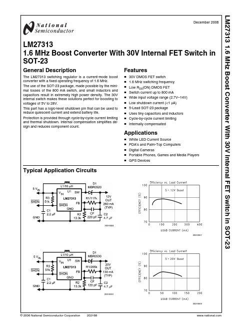
■ 30V DMOS FET switch ■ 1.6 MHz switching frequency ■ Low RDS(ON) DMOS FET ■ Switch current up to 800 mA ■ Wide input voltage range (2.7V–14V) ■ Low shutdown current (<1 µA) ■ 5-Lead SOT-23 package ■ Uses tiny capacitors and inductors ■ Cycle-by-cycle current limiting ■ Internally compensated
General Description
The LM27313 switching regulator is a current-mode boost converter with a fixed operating frequency of 1.6 MHz.
用LM317和UA741制作的0-±15V稳压电源

用LM317和UA741制作的0-±15V稳压电源本文向大家介绍一款能够从0起调的跟踪式稳压电源,由于采用LM317和LM337三端可调集成稳压器,故内部有限流、短路和热保护等完善功能。
其独特之处:仅用一个单连电位器即能实现正、负电压同步调节,具有线路简单、调节方便、性能优良、成本低廉等特点,适合无线电爱好者做实验之用。
工作原理:整机电路如图所示。
电源输入部分为常见的变压器降压与桥式整流,加大电容滤波,获得上下对称的±22V直流电压。
其中还派生出另两组±6.8V辅助电压,分别接在运放IC4和运放IC3的V+与V-端,以保证IC3、IC4的工作电压不超过极限范围。
下面具体分述稳压部分: 1.正输出电路由稳压器IC1及相关元器件组成,通常接在稳压器IC1的调节端上电位器另一端是接地的。
假如RP1电阻调至0值,那么输出电压Vout=1.2V,即电路内部基准电压为1.2V,同时在电阻R3上产生10mA恒流,只要改变RP1的阻值即可改变输出电压。
这里,将RP1接地端改接在运放IC3的输出端,并设法使IC3的输出电压为-1.2V,以抵消IC1的基准电压+1.2V,这样便可实现从0起调,要实现上述目的也很简单,只要将运放IC3连成差分放大器,进行减法运算即可。
由图可知,同相输入端电压为V1,而反相输入端电压为V2,因R4=R5=R6=R7,故IC3的输出端电压VO=R5/R4 乘以(V1-V2)=-1.2V,也可得出稳压器IC1的输出电压+Vout=5mA乘以R3+10mA乘以PR1-1.2V。
2.负输出电路由稳压器IC2及相关元件组成,这里省去了IC2调节端上原设置的电位器RP3,改接在运放IC4的输出端,由IC4的输出电压控制调节端,同样可以达到调节稳压器的输出电压目的。
由于运放IC4接成增益为1的反相。
基于LM317LM337的连续可调直流稳压电源
基于LM317、LM337的连续可调直流稳压电源为了方便配合以后的电路板,我特意的制作了双路输出连续可调直流稳压电源,经过查找资料,比较多种电源方案后,最终确定采用以LM317、LM337为核心的双电源方案,其电压连续可调。
内置有多重保护电路,该电源内阻小,电压稳定,噪声极低,输出纹波小。
虽然功率较小,但是用于给一般的电子小制作供电也足够了,况且其输出电压连续可调,使用起来十分方便。
LM317的封装图LM337的封装图稳压管LM317的内部原理图稳压管LM337的内部原理图一、工作原理本直流电源由电源、滤波、保护、稳压等四个基本模块组成,如图I框图所示,其电路图如图II所示,PCB图如图III所示。
图I图II图III图IV电源实物图图V电源实物图1、电源变压器采用降压变压器,将电网交流电压220V变换成需要的交流电压。
此交流电压经过整流后,可获得电子设备所需要的直流电压。
2、整流电路利用单相桥式整流电路,把50Hz的交流电变换为方向不变但大小仍有脉动的直流电。
其优点是电压较高、纹波电压较小,变压器的利用率高。
本电路用4个Diode IN4007做成一个全桥整流,电流大,配合本电路的大滤波电容,使得本电源的瞬间大电流的供电特性好、噪声小、反映速度快、输出纹波小。
3、滤波电路采用电容滤波电路,将整流电路输出的脉动成分大部分滤除,得到比较平滑的直流电。
本电路采用4个2200UF/25V的电解电容两两并联使输出电压更加平滑,电源瞬间特性好,适合带感性负载,如电机的启动。
两个并联的2200V电容同时并联了一只0.1UF的瓷片电容,滤去高频干扰,使输入到集成电路的直流电尽可能的平滑和纯净。
4、稳压电路由LM317输出正电源,LM337输出负电源。
LM317和LM337均使用了内部热过载,包含过流保护、热关断和安全工作区补偿等完善的保护电路,使得电源可以省去保险丝等易损耗器件。
5、保护电路因为线性电源发热量较大,所以本电路在制作的时候覆了地,用于帮助散热。
5v 3.3 1.2 1.5 1.8 2.5V稳压电源芯片大全

LM317LZ 1.2V to 37V三端正可调稳压器(0.1A) LM317T 1.2V to 37V三端正可调稳压器(1.5A) LM317K 1.2V to 37V三端正可调稳压器(1.5A)LM133K 三端可调-1.2V to -37V稳压器(3.0A) LM333K 三端可调-1.2V to -37V稳压器(3.0A) LM337K 三端可调-1.2V to -37V稳压器(1.5A) LM337T 三端可调-1.2V to -37V稳压器(1.5A) LM337LZ 三端可调-1.2V to -37V稳压器(0.1A)LM150K 三端可调1.2V to 32V稳压器(3A)LM350K 三端可调1.2V to 32V稳压器(3A)LM350T 三端可调1.2V to 32V稳压器(3A)LM138K 三端正可调1.2V to 32V稳压器(5A) LM338T 三端正可调1.2V to 32V稳压器(5A) LM338K 三端正可调1.2V to 32V稳压器(5A)LM336-2.5 2.5V精密基准电压源LM336-5.0 5.0V精密基准电压源LM385-1.2 1.2V精密基准电压源LM385-2.5 2.5V精密基准电压源LM399H 6.9999V精密基准电压源LM431ACZ 精密可调2.5V to 36V基准稳压源LM723 高精度可调2V to 37V稳压器LM105 高精度可调4.5V to 40V稳压器LM305 高精度可调4.5V to40V稳压器MC1403 2.5V基准电压源MC34063 DC-DC直流变换器SG3524 脉宽调制开关电源控制器TL431 精密可调2.5V to 36V基准稳压源TL494 脉宽调制开关电源控制器TL497 频率调制开关电源控制器TL7705 电池供电/欠压控制器。
LM321中文资料_数据手册_参数

Device Information(1)
PART NUMBER PACKAGE
BODY SIZE (NOM)
LM321
SOT (5)
2.90 mm × 1.60 mm
(1) For all available packages, see the orderable addendum at the end of the datasheet.
7.3 Feature Description................................................... 7 7.4 Device Functional Modes.......................................... 8 8 Application and Implementation .......................... 9 8.1 Application Information.............................................. 9 8.2 Typical Applications ................................................ 10 9 Power Supply Recommendations...................... 13 10 Layout................................................................... 13 10.1 Layout Guidelines ................................................. 13 10.2 Layout Example .................................................... 14 11 Device and Documentation Support ................. 15 11.1 Trademarks ........................................................... 15 11.2 Electrostatic Discharge Caution ............................ 15 11.3 Glossary ................................................................ 15 12 Mechanical, Packaging, and Orderable Information ........................................................... 15
金升阳 MBP300-2A27D27 AC DC 模块电源说明书
300W ,165-264V AC 输入,双路输出AC/DC电池充电模块电源RoHS产品特点z 整机系统待机功耗低,各技术指标符合DL/T721-2013等配网自动化行业标准z 最大瞬时过功率达351Wz 具备电池充电功能,可对24V 铅酸电池充电,系统配套电池使用,可实现不间断供电z 具有电池充放电管理功能,电池状态显示,电池活化,外部通信和控制功能z 输出过流,过压保护z 2500V AC 高隔离电压z 工业级工作温度:-40℃~+70℃z 接线式安装MBP300-2A27D27是我司为客户提供的双路输出AC/DC 电池充电模块电源。
本产品电网适应能力强,可在较宽输入电压范围内工作,具有输出过压、过流等保护功能。
另外,本产品具有电源状态显示及智能充电功能,可对外接的24V 铅酸电池充电,在交流断电时电池可不间断的对负载供电;具有电池活化功能,手动或通过外部信号自动对电池进行活化维护;具有防止电池过放电的保护功能。
是专为配电自动化终端(DTU/FTU )设计的电池充电式模块电源;可广泛用于电力行业开闭所、配电所、环网柜、智能箱式变电站、智能开关控制器和其它行业需要不间断供电的场合。
短路保护全范围输入,断开电池打嗝式,可持续短路,自恢复过流保护16----A 过压保护全电压输入,不接电池,故障消失后自恢复供电29--33V 掉电保持时间全范围输入,Po=14W-- 1.5--s 注:*纹波和噪声的测试方法采用靠测法,具体操作方法参见《AC-DC模块电源应用指南》。
图1电源内部原理图图2电源内部隔离图1、充电及工作指示灯2、电池放电指示灯3、电池活化指示灯4、电池欠压指示灯5、电源故障指示灯6、手动活化启动按键7、手动活化退出按键8、手动电池投入按键9、手动电池退出按键10、接线端子端子号端子名称定义端子号端子名称定义端子号端子名称定义1ACL 交流输入L 相9VH 电源故障告警输出17Vo+负载输出正2PE 保护接地10HK 遥控活化启动18Vo+负载输出正3ACN 交流输入N 相11HG 遥控活化退出19B+电池接入正4NC 无电气连接12BG 遥控电池退出20B+电池接入正5VC 告警输入正13RL 活化放电负载正21B-电池接入负6POK输入失电告警输出14VG遥控公共接点22B-电池接入负7HOK电池活化状态输出15Vo-负载输出负8VL电池欠压告警输出16Vo-负载输出负2.接线示意图保险丝接线说明:K1K2K3为用户CPU等控制的继电器触点,R为电池活化放电电阻,负载为用户正常负载,电池为24V电池组。
LM2574M-5.0
LM2574/LM2574HVSIMPLE SWITCHER ™0.5A Step-Down Voltage RegulatorGeneral DescriptionThe LM2574series of regulators are monolithic integrated circuits that provide all the active functions for a step-down (buck)switching regulator,capable of driving a 0.5A load with excellent line and load regulation.These devices are available in fixed output voltages of 3.3V,5V,12V,15V,and an adjustable output version.Requiring a minimum number of external components,these regulators are simple to use and include internal frequency compensation and a fixed-frequency oscillator.The LM2574series offers a high-efficiency replacement for popular three-terminal linear regulators.Because of its high efficiency,the copper traces on the printed circuit board are normally the only heat sinking needed.A standard series of inductors optimized for use with the LM2574are available from several different manufacturers.This feature greatly simplifies the design of switch-mode power supplies.Other features include a guaranteed ±4%tolerance on out-put voltage within specified input voltages and output load conditions,and ±10%on the oscillator frequency.External shutdown is included,featuring 50µA (typical)standby cur-rent.The output switch includes cycle-by-cycle current limit-ing,as well as thermal shutdown for full protection under fault conditions.Featuresn 3.3V,5V,12V,15V,and adjustable output versions n Adjustable version output voltage range,1.23V to 37V (57V for HV version)±4%max over line and load conditionsn Guaranteed 0.5A output currentn Wide input voltage range,40V,up to 60V for HV version n Requires only 4external components n 52kHz fixed frequency internal oscillatorn TTL shutdown capability,low power standby mode n High efficiencyn Uses readily available standard inductorsn Thermal shutdown and current limit protectionApplicationsn Simple high-efficiency step-down (buck)regulator n Efficient pre-regulator for linear regulators n On-card switching regulatorsnPositive to negative converter (Buck-Boost)Typical Application(Fixed Output Voltage Versions)Patent PendingSIMPLE SWITCHER ™is a trademark of National Semiconductor CorporationDS011394-1Note:Pin numbers are for 8-pin DIP package.June 1999LM2574/LM2574HV SIMPLE SWITCHER 0.5A Step-Down Voltage Regulator©1999National Semiconductor Corporation Connection Diagrams8-LeadDIPDS011394-2*No internal connection,but should be soldered to PC board for best heat transfer.Top ViewOrder Number LM2574-3.3HVN,LM2574HVN-5.0,LM2574HVN-12,LM2574HVN-15,LM2574HVN-ADJ,LM2574N-3.3,LM2574N-5.0,LM2574N-12,LM2574N-15or LM2574N-ADJ See NS Package Number N08A14-Lead Wide Surface Mount (WM) 2Absolute Maximum Ratings(Note1)If Military/Aerospace specified devices are required, please contact the National Semiconductor Sales Office/ Distributors for availability and specifications. Maximum Supply VoltageLM257445V LM2574HV63V ON/OFF Pin Input Voltage−0.3V≤V≤+V IN Output Voltage to Ground(Steady State)−1V Minimum ESD Rating(C=100pF,R=1.5kΩ)2kV Storage Temperature Range−65˚C to+150˚C Lead Temperature(Soldering,10seconds)260˚C Maximum Junction Temperature150˚C Power Dissipation Internally LimitedOperating RatingsTemperature RangeLM2574/LM2574HV−40˚C≤T J≤+125˚C Supply VoltageLM257440V LM2574HV60VLM2574-3.3,LM2574HV-3.3Electrical CharacteristicsSpecifications with standard type face are for T J=25˚C,and those with boldface type apply over full Operating Tempera-ture Range.Symbol Parameter Conditions LM2574-3.3Units(Limits)LM2574HV-3.3Typ Limit(Note2)SYSTEM PARAMETERS(Note3)Test Circuit Figure2V OUT Output Voltage V IN=12V,I LOAD=100mA 3.3V3.234V(Min)3.366V(Max)V OUT Output Voltage 4.75V≤V IN≤40V,0.1A≤I LOAD≤0.5A 3.3V LM2574 3.168/3.135V(Min)3.432/3.465V(Max)V OUT Output Voltage 4.75V≤V IN≤60V,0.1A≤I LOAD≤0.5A 3.3LM2574HV 3.168/3.135V(Min)3.450/3.482V(Max)ηEfficiency V IN=12V,I LOAD=0.5A72%LM2574-5.0,LM2574HV-5.0Electrical CharacteristicsSpecifications with standard type face are for T J=25˚C,and those with boldface type apply over full Operating Tempera-ture Range.Symbol Parameter Conditions LM2574-5.0Units(Limits)LM2574HV-5.0Typ Limit(Note2)SYSTEM PARAMETERS(Note3)Test Circuit Figure2V OUT Output Voltage V IN=12V,I LOAD=100mA5V4.900V(Min)5.100V(Max)V OUT Output Voltage7V≤V IN≤40V,0.1A≤I LOAD≤0.5A5V LM2574 4.800/4.750V(Min)5.200/5.250V(Max)V OUT Output Voltage7V≤V IN≤60V,0.1A≤I LOAD≤0.5A5LM2574HV 4.800/4.750V(Min)5.225/5.275V(Max)ηEfficiency V IN=12V,I LOAD=0.5A77%3LM2574-12,LM2574HV-12Electrical CharacteristicsSpecifications with standard type face are for T J=25˚C,and those with boldface type apply over full Operating Tempera-ture Range.Symbol Parameter Conditions LM2574-12Units(Limits)LM2574HV-12Typ Limit(Note2)SYSTEM PARAMETERS(Note3)Test Circuit Figure2V OUT Output Voltage V IN=25V,I LOAD=100mA12V11.76V(Min)12.24V(Max) V OUT Output Voltage15V≤V IN≤40V,0.1A≤I LOAD≤0.5A12V LM257411.52/11.40V(Min)12.48/12.60V(Max) V OUT Output Voltage15V≤V IN≤60V,0.1A≤I LOAD≤0.5A12LM2574HV11.52/11.40V(Min)12.54/12.66V(Max)ηEfficiency V IN=15V,I LOAD=0.5A88%LM2574-15,LM2574HV-15Electrical CharacteristicsSpecifications with standard type face are for T J=25˚C,and those with boldface type apply over full Operating Tempera-ture Range.Symbol Parameter Conditions LM2574-15Units(Limits)LM2574HV-15Typ Limit(Note2)SYSTEM PARAMETERS(Note3)Test Circuit Figure2V OUT Output Voltage V IN=30V,I LOAD=100mA15V14.70V(Min)15.30V(Max) V OUT Output Voltage18V≤V IN≤40V,0.1A≤I LOAD≤0.5A15V LM257414.40/14.25V(Min)15.60/15.75V(Max) V OUT Output Voltage18V≤V IN≤60V,0.1A≤I LOAD≤0.5A15LM2574HV14.40/14.25V(Min)15.68/15.83V(Max)ηEfficiency V IN=18V,I LOAD=0.5A88%LM2574-ADJ,LM2574HV-ADJElectrical CharacteristicsSpecifications with standard type face are for T J=25˚C,and those with boldface type apply over full Operating Tempera-ture Range.Unless otherwise specified,V IN=12V,I LOAD=100mA.Symbol Parameter Conditions LM2574-ADJ Units(Limits)LM2574HV-ADJTyp Limit(Note2)SYSTEM PARAMETERS(Note3)Test Circuit Figure2V FB Feedback Voltage V IN=12V,I LOAD=100mA 1.230V1.217V(Min)1.243V(Max) 4LM2574-ADJ,LM2574HV-ADJElectrical Characteristics(Continued)Specifications with standard type face are for T J=25˚C,and those with boldface type apply over full Operating Tempera-ture Range.Unless otherwise specified,V IN=12V,I LOAD=100mA.Symbol Parameter Conditions LM2574-ADJ Units(Limits)LM2574HV-ADJTyp Limit(Note2)SYSTEM PARAMETERS(Note3)Test Circuit Figure2V FB Feedback Voltage7V≤V IN≤40V,0.1A≤I LOAD≤0.5A 1.230V LM2574V OUT Programmed for5V.Circuit of Figure2 1.193/1.180V(Min)1.267/1.280V(Max)V FB Feedback Voltage7V≤V IN≤60V,0.1A≤I LOAD≤0.5A 1.230LM2574HV V OUT Programmed for5V.Circuit of Figure2 1.193/1.180V(Min)1.273/1.286V(Max)ηEfficiency V IN=12V,V OUT=5V,I LOAD=0.5A77%All Output Voltage VersionsElectrical CharacteristicsSpecifications with standard type face are for T J=25˚C,and those with boldface type apply over full Operating Tempera-ture Range.Unless otherwise specified,V IN=12V for the3.3V,5V,and Adjustable version,V IN=25V for the12V version,and V IN=30V for the15V version.I LOAD=100mA.Symbol Parameter Conditions LM2574-XX Units(Limits)LM2574HV-XXTyp Limit(Note2)DEVICE PARAMETERSAdjustable Version Only,V OUT=5V50100/500nAI b Feedback BiasCurrentf O Oscillator Frequency(see Note10)52kHz47/42kHz(Min)58/63kHz(Max)V SAT Saturation Voltage I OUT=0.5A(Note4)0.9V1.2/1.4V(max)DC Max Duty Cycle(Note5)98% (ON)93%(Min)I CL Current Limit Peak Current,(Notes4,10) 1.0A0.7/0.65A(Min)1.6/1.8A(Max)I L Output Leakage(Notes6,7)Output=0V2mA(Max)Current Output=−1V7.5mAOutput=−1V30mA(Max)I Q Quiescent Current(Note6)5mA10mA(Max)I STBY Standby Quiescent ON/OFF Pin=5V(OFF)50µACurrent200µA(Max)θJA Thermal Resistance N Package,Junction to Ambient(Note8)92θJA N Package,Junction to Ambient(Note9)72˚C/WθJA M Package,Junction to Ambient(Note8)102θJA M Package,Junction to Ambient(Note9)785All Output VoltageVersionsElectrical Characteristics (Continued)Specifications with standard type face are for T J =25˚C,and those with boldface type apply over full Operating Tempera-ture Range.Unless otherwise specified,V IN =12V for the 3.3V,5V,and Adjustable version,V IN =25V for the 12V version,and V IN =30V for the 15V version.I LOAD =100mA.SymbolParameterConditionsLM2574-XX Units (Limits)LM2574HV-XXTypLimit (Note 2)ON /OFF CONTROL Test Circuit Figure 2V IH ON /OFF Pin Logic V OUT =0V1.42.2/2.4V(Min)V IL Input Level V OUT =Nominal Output Voltage 1.2 1.0/0.8V(Max)I H ON /OFF Pin Input ON /OFF Pin =5V (OFF)12µA Current30µA(Max)I ILON /OFF Pin =0V (ON)µA 10µA(Max)Note 1:Absolute Maximum Ratings indicate limits beyond which damage to the device may occur.Operating Ratings indicate conditions for which the device is in-tended to be functional,but do not guarantee specific performance limits.For guaranteed specifications and test conditions,see the Electrical Characteristics.Note 2:All limits guaranteed at room temperature (Standard type face)and at temperature extremes (bold type face).All room temperature limits are 100%produc-tion tested.All limits at temperature extremes are guaranteed via correlation using standard Statistical Quality Control (SQC)methods.All limits are used to calculate Average Outgoing Quality Level.Note 3:External components such as the catch diode,inductor,input and output capacitors can affect switching regulator system performance.When the LM2574is used as shown in the Figure 2test circuit,system performance will be as shown in system parameters section of Electrical Characteristics.Note 4:Output pin sourcing current.No diode,inductor or capacitor connected to output pin.Note 5:Feedback pin removed from output and connected to 0V.Note 6:Feedback pin removed from output and connected to +12V for the Adjustable,3.3V,and 5V versions,and +25V for the 12V and 15V versions,to force the output transistor OFF.Note 7:V IN =40V (60V for high voltage version).Note 8:Junction to ambient thermal resistance with approximately 1square inch of printed circuit board copper surrounding the leads.Additional copper area will lower thermal resistance further.See application hints in this data sheet and the thermal model in Switchers Made Simple software.Note 9:Junction to ambient thermal resistance with approximately 4square inches of 1oz.(0.0014in.thick)printed circuit board copper surrounding the leads.Ad-ditional copper area will lower thermal resistance further.(See Note 8.)Note 10:The oscillator frequency reduces to approximately 18kHz in the event of an output short or an overload which causes the regulated output voltage to drop approximately 40%from the nominal output voltage.This self protection feature lowers the average power dissipation of the IC by lowering the minimum duty cycle from 5%down to approximately 2%.Typical Performance Characteristics(Circuit of Figure 2)Normalized Output VoltageDS011394-27Line RegulationDS011394-28Dropout VoltageDS011394-29 6Typical Performance Characteristics(Circuitof Figure2)(Continued)Current LimitDS011394-30Supply CurrentDS011394-31StandbyQuiescent CurrentDS011394-32Oscillator FrequencyDS011394-33Switch SaturationVoltageDS011394-34EfficiencyDS011394-35Minimum Operating VoltageDS011394-36Supply Currentvs Duty CycleDS011394-37Feedback Voltagevs Duty CycleDS011394-38 7Typical Performance Characteristics(Circuitof Figure2)(Continued) FeedbackPin CurrentDS011394-39Junction to AmbientThermal ResistanceDS011394-40Continuous Mode Switching WaveformsV OUT=5V,500mA Load Current,L=330µHDS011394-6Notes:A:Output Pin Voltage,10V/divB:Inductor Current,0.2A/divC:Output Ripple Voltage,20mV/div,AC-CoupledHorizontal Time Base:5µs/divDiscontinuous Mode Switching WaveformsV OUT=5V,100mA Load Current,L=100µHDS011394-7Notes:A:Output Pin Voltage,10V/divB:Inductor Current,0.2A/divC:Output Ripple Voltage,20mV/div,AC-CoupledHorizontal Time Base:5µs/div500mA Load Transient Response for ContinuousMode Operation.L=330µH,C OUT=300µFDS011394-8Notes:A:Output Voltage,50mV/div.AC CoupledB:100mA to500mA Load PulseHorizontal Time Base:200µs/div250mA Load Transient Response for DiscontinuousMode Operation.L=68µH,C OUT=470µFDS011394-9Notes:A:Output Voltage,50mV/div.AC CoupledB:50mA to250mA Load PulseHorizontal Time Base:200µs/div8Block DiagramDS011394-10R1=1k3.3V,R2=1.7k5V,R2=3.1k12V,R2=8.84k15V,R2=11.3kFor Adj.VersionR1=Open,R2=0ΩNote:Pin numbers are for the8-pin DIP package.FIGURE1.9Test Circuit andLayout GuidelinesAs in any switching regulator,layout is very important.Rap-idly switching currents associated with wiring inductance generate voltage transients which can cause problems.For minimal inductance and ground loops,the length of the leads indicated by heavy lines should be kept as short as pos-sible .Single-point grounding (as indicated)or ground plane construction should be used for best results.When using the Adjustable version,physically locate the programming resis-tors near the regulator,to keep the sensitive feedback wiring short.Fixed Output Voltage VersionsDS011394-11C IN —22µF,75VAluminum ElectrolyticC OUT —220µF,25VAluminum ElectrolyticD1—Schottky,11DQ06L1—330µH,52627(for 5V in,3.3V out,use 100µH,RL-1284-100)R1—2k,0.1%R2— 6.12k,0.1%Adjustable Output Voltage VersionFIGURE 2. 10Test Circuit andLayout Guidelines(Continued)U.S.SourceNote1:Pulse Engineering,(619)674-8100 P.O.Box12236,San Diego,CA92112Note2:Renco Electronics Inc.,(516)586-5566 60Jeffryn Blvd.East,Deer Park,NY11729*Contact ManufacturerEuropean SourceNote3:NPI/APC+44(0)634290588 47Riverside,Medway City EstateStrood,Rochester,Kent *Contact ManufacturerInductor Pulse Eng.Renco NPIValue(Note1)(Note2)(Note3)68µH*RL-1284-68-43NP5915100µH*RL-1284-100-43NP5916150µH52625RL-1284-150-43NP5917220µH52626RL-1284-220-43NP5918/5919330µH52627RL-1284-330-43NP5920/5921470µH52628RL-1284-470-43NP5922680µH52629RL-1283-680-43NP59231000µH52631RL-1283-1000-43*1500µH*RL-1283-1500-43*2200µH*RL-1283-2200-43*FIGURE3.Inductor Selection byManufacturer’s Part Number11LM2574Series BuckRegulator Design ProcedurePROCEDURE(Fixed Output Voltage Versions)EXAMPLE(Fixed Output Voltage Versions)Given:V OUT=Regulated Output Voltage(3.3V,5V,12V,or15V) V IN(Max)=Maximum Input VoltageI LOAD(Max)=Maximum Load Current Given:V OUT=5VV IN(Max)=15VI LOAD(Max)=0.4A1.Inductor Selection(L1)A.Select the correct Inductor value selection guide from Fig-ures4,5,6,or Figure7.(Output voltages of3.3V,5V,12V or 15V respectively).For other output voltages,see the design procedure for the adjustable version.B.From the inductor value selection guide,identify the induc-tance region intersected by V IN(Max)and I LOAD(Max).C.Select an appropriate inductor from the table shown in Fig-ure3.Part numbers are listed for three inductor manufactur-ers.The inductor chosen must be rated for operation at the LM2574switching frequency(52kHz)and for a current rating of1.5x I LOAD.For additional inductor information,see the in-ductor section in the Application Hints section of this data sheet.1.Inductor Selection(L1)e the selection guide shown in Figure5.B.From the selection guide,the inductance area intersected by the15V line and0.4A line is330.C.Inductor value required is330µH.From the table in Figure 3,choose Pulse Engineering PE-52627,Renco RL-1284-330, or NPI NP5920/5921.2.Output Capacitor Selection(C OUT)A.The value of the output capacitor together with the inductor defines the dominate pole-pair of the switching regulator loop. For stable operation and an acceptable output ripple voltage, (approximately1%of the output voltage)a value between 100µF and470µF is recommended.B.The capacitor’s voltage rating should be at least1.5times greater than the output voltage.For a5V regulator,a rating of at least8V is appropriate,and a10V or15V rating is recom-mended.Higher voltage electrolytic capacitors generally have lower ESR numbers,and for this reason it may be necessary to se-lect a capacitor rated for a higher voltage than would normally be needed.2.Output Capacitor Selection(C OUT)A.C OUT=100µF to470µF standard aluminum electrolytic.B.Capacitor voltage rating=20V.3.Catch Diode Selection(D1)A.The catch-diode current rating must be at least1.5times greater than the maximum load current.Also,if the power supply design must withstand a continuous output short,the diode should have a current rating equal to the maximum cur-rent limit of the LM2574.The most stressful condition for this diode is an overload or shorted output condition.B.The reverse voltage rating of the diode should be at least1.25times the maximum input voltage.3.Catch Diode Selection(D1)A.For this example,a1A current rating is adequate.e a20V1N5817or SR102Schottky diode,or any of the suggested fast-recovery diodes shown in Figure9.4.Input Capacitor(C IN)An aluminum or tantalum electrolytic bypass capacitor located close to the regulator is needed for stable operation.4.Input Capacitor(C IN)A22µF aluminum electrolytic capacitor located near the input and ground pins provides sufficient bypassing.12LM2574Series BuckRegulator Design Procedure(Continued)INDUCTOR VALUE SELECTION GUIDES(For Continuous Mode Operation)DS011394-26FIGURE4.LM2574HV-3.3Inductor Selection GuideDS011394-13 FIGURE5.LM2574HV-5.0Inductor Selection GuideDS011394-14 FIGURE6.LM2574HV-12Inductor Selection GuideDS011394-15 FIGURE7.LM2574HV-15Inductor Selection Guide 13LM2574Series BuckRegulator Design Procedure(Continued)PROCEDURE(Adjustable Output Voltage Versions)EXAMPLE(Adjustable Output Voltage Versions) Given:V OUT=Regulated Output VoltageV IN(Max)=Maximum Input VoltageI LOAD(Max)=Maximum Load CurrentF=Switching Frequency(Fixed at52kHz)Given:V OUT=24VV IN(Max)=40VI LOAD(Max)=0.4AF=52kHz1.Programming Output Voltage(Selecting R1and R2,asshown in Figure2)Use the following formula to select the appropriate resistorvalues.R1can be between1k and5k.(For best temperature coeffi-cient and stability with time,use1%metal film resistors)1.Programming Output Voltage(Selecting R1and R2)R2=1k(19.51−1)=18.51k,closest1%value is18.7k2.Inductor Selection(L1)A.Calculate the inductor Volt•microsecond constant,E•T(V•µs),from the following formula:e the E•T value from the previous formula and matchit with the E•T number on the vertical axis of the InductorValue Selection Guide shown in Figure8.C.On the horizontal axis,select the maximum load current.D.Identify the inductance region intersected by the E•Tvalue and the maximum load current value,and note the in-ductor value for that region.E.Select an appropriate inductor from the table shown in Fig-ure3.Part numbers are listed for three inductor manufactur-ers.The inductor chosen must be rated for operation at theLM2574switching frequency(52kHz)and for a current ratingof1.5x I LOAD.For additional inductor information,see the in-ductor section in the application hints section of this datasheet.2.Inductor Selection(L1)A.Calculate E•T(V•µs)B.E•T=185V•µsC.I LOAD(Max)=0.4AD.Inductance Region=1000E.Inductor Value=1000µH Choose from Pulse Engineer-ing Part#PE-52631,or Renco Part#RL-1283-1000.DS011394-16FIGURE8.LM2574HV-ADJ Inductor Selection Guide14LM2574Series Buck RegulatorDesign Procedure(Continued)PROCEDURE(Adjustable Output Voltage Versions)EXAMPLE(Adjustable Output Voltage Versions)3.Output Capacitor Selection(C OUT)A.The value of the output capacitor together with the inductordefines the dominate pole-pair of the switching regulator loop.For stable operation,the capacitor must satisfy the followingrequirement:The above formula yields capacitor values between5µF and1000µF that will satisfy the loop requirements for stable op-eration.But to achieve an acceptable output ripple voltage,(approximately1%of the output voltage)and transient re-sponse,the output capacitor may need to be several timeslarger than the above formula yields.B.The capacitor’s voltage rating should be at last1.5timesgreater than the output voltage.For a24V regulator,a ratingof at least35V is recommended.Higher voltage electrolytic capacitors generally have lowerESR numbers,and for this reasion it may be necessary to se-lect a capacitor rate for a higher voltage than would normallybe needed.3.Output Capacitor Selection(C OUT)However,for acceptable output ripple voltage selectC OUT≥100µFC OUT=100µF electrolytic capacitor4.Catch Diode Selection(D1)A.The catch-diode current rating must be at least1.5timesgreater than the maximum load current.Also,if the powersupply design must withstand a continuous output short,thediode should have a current rating equal to the maximum cur-rent limit of the LM2574.The most stressful condition for thisdiode is an overload or shorted output condition.Suitable di-odes are shown in the selection guide of Figure9.B.The reverse voltage rating of the diode should be at least1.25times the maximum input voltage.4.Catch Diode Selection(D1)A.For this example,a1A current rating is adequate.e a50V MBR150or11DQ05Schottky diode,or any ofthe suggested fast-recovery diodes in Figure9.5.Input Capacitor(C IN)An aluminum or tantalum electrolytic bypass capacitor locatedclose to the regulator is needed for stable operation.5.Input Capacitor(C IN)A22µF aluminum electrolytic capacitor located near the inputand ground pins provides sufficient bypassing.See(Figure9).To further simplify the buck regulator design procedure,Na-tional Semiconductor is making available computer designsoftware to be used with the Simple Switcher line of switchingregulators.Switchers Made Simple(version3.3)is availableon a(31⁄2")diskette for IBM compatible computers from a Na-tional Semiconductor sales office in your area.15LM2574Series BuckRegulator Design Procedure(Continued)Application HintsINPUT CAPACITOR(C IN)To maintain stability,the regulator input pin must be by-passed with at least a22µF electrolytic capacitor.The ca-pacitor’s leads must be kept short,and located near the regulator.If the operating temperature range includes temperatures below−25˚C,the input capacitor value may need to be larger.With most electrolytic capacitors,the capacitance value decreases and the ESR increases with lower tempera-tures and age.Paralleling a ceramic or solid tantalum ca-pacitor will increase the regulator stability at cold tempera-tures.For maximum capacitor operating lifetime,the capacitor’s RMS ripple current rating should be greater than INDUCTOR SELECTIONAll switching regulators have two basic modes of operation: continuous and discontinuous.The difference between the two types relates to the inductor current,whether it is flowing continuously,or if it drops to zero for a period of time in the normal switching cycle.Each mode has distinctively different operating characteristics,which can affect the regulator per-formance and requirements.The LM2574(or any of the Simple Switcher family)can be used for both continuous and discontinuous modes of opera-tion.In many cases the preferred mode of operation is in the con-tinuous mode.It offers better load regulation,lower peak switch,inductor and diode currents,and can have lower out-put ripple voltage.But it does require relatively large inductor values to keep the inductor current flowing continuously,es-pecially at low output load currents.To simplify the inductor selection process,an inductor selec-tion guide(nomograph)was designed(see Figure4through Figure8).This guide assumes continuous mode operation, and selects an inductor that will allow a peak-to-peak induc-tor ripple current(∆I IND)to be a certain percentage of the maximum design load current.In the LM2574SIMPLE SWITCHER,the peak-to-peak inductor ripple current per-centage(of load current)is allowed to change as different design load currents are selected.By allowing the percent-age of inductor ripple current to increase for lower current applications,the inductor size and value can be kept rela-tively low.V R1Amp DiodesSchottky Fast Recovery20V1N5817SR102MBR120P30V1N5818SR10311DQ03TheMBR130P following10JQ030diodes40V1N5819are allSR104rated to11DQ04100V11JQ04MBR140P50V MBR15011DF1SR10510JF111DQ05MUR11011JQ05HER10260V MBR160SR10611DQ0611JQ0690V11DQ09FIGURE9.Diode Selection Guide 16Application Hints(Continued)INDUCTOR RIPPLE CURRENTWhen the switcher is operating in the continuous mode,the inductor current waveform ranges from a triangular to a saw-tooth type of waveform (depending on the input voltage).For a given input voltage and output voltage,the peak-to-peak amplitude of this inductor current waveform remains con-stant.As the load current rises or falls,the entire sawtooth current waveform also rises or falls.The average DC value of this waveform is equal to the DC load current (in the buck regulator configuration).If the load current drops to a low enough level,the bottom of the sawtooth current waveform will reach zero,and the switcher will change to a discontinuous mode of operation.This is a perfectly acceptable mode of operation.Any buck switching regulator (no matter how large the inductor value is)will be forced to run discontinuous if the load current is light enough.The curve shown in Figure 10illustrates how the peak-to-peak inductor ripple current (∆I IND )is allowed to change as different maximum load currents are selected,and also how it changes as the operating point varies from the upper bor-der to the lower border within an inductance region (see In-ductor Selection guides).Consider the following example:V OUT =5V @0.4AV IN =10V minimum up to 20V maximumThe selection guide in Figure 5shows that for a 0.4A load current,and an input voltage range between 10V and 20V,the inductance region selected by the guide is 330µH.This value of inductance will allow a peak-to-peak inductor ripple current (∆I IND )to flow that will be a percentage of the maxi-mum load current.For this inductor value,the ∆I IND will also vary depending on the input voltage.As the input voltage in-creases to 20V,it approaches the upper border of the induc-tance region,and the inductor ripple current increases.Re-ferring to the curve in Figure 10,it can be seen that at the 0.4A load current level,and operating near the upper border of the 330µH inductance region,the ∆I IND will be 53%of 0.4A,or 212mA p-p.This ∆I IND is important because from this number the peak inductor current rating can be determined,the minimum load current required before the circuit goes to discontinuous op-eration,and also,knowing the ESR of the output capacitor,the output ripple voltage can be calculated,or conversely,measuring the output ripple voltage and knowing the ∆I IND ,the ESR can be calculated.From the previous example,the Peak-to-peak Inductor Ripple Current (∆I IND )=212mA p-p.Once the ∆IND value is known,the following three formulas can be used to calculate additional information about the switching regulator circuit:1.Peak Inductor or peak switch current2.Minimum load current before the circuit becomes dis-continuous3.Output Ripple Voltage =(∆I IND )x (ESR of C OUT )The selection guide chooses inductor values suitable for continuous mode operation,but if the inductor value chosen is prohibitively high,the designer should investigate the pos-sibility of discontinuous operation.The computer design soft-ware Switchers Made Simple will provide all component values for discontinuous (as well as continuous)mode of op-eration.Inductors are available in different styles such as pot core,toroid,E-frame,bobbin core,etc.,as well as different core materials,such as ferrites and powdered iron.The least ex-pensive,the bobbin core type,consists of wire wrapped on a ferrite rod core.This type of construction makes for an inex-pensive inductor,but since the magnetic flux is not com-pletely contained within the core,it generates more electro-magnetic interference (EMI).This EMl can cause problems in sensitive circuits,or can give incorrect scope readings be-cause of induced voltages in the scope probe.The inductors listed in the selection chart include powdered iron toroid for Pulse Engineering,and ferrite bobbin core for Renco.An inductor should not be operated beyond its maximum rated current because it may saturate.When an inductor be-gins to saturate,the inductance decreases rapidly and the inductor begins to look mainly resistive (the DC resistance of the winding).This can cause the inductor current to rise very rapidly and will affect the energy storage capabilities of the inductor and could cause inductor overheating.Different in-ductor types have different saturation characteristics,and this should be kept in mind when selecting an inductor.The inductor manufacturers’data sheets include current and en-ergy limits to avoid inductor saturation.OUTPUT CAPACITORAn output capacitor is required to filter the output voltage and is needed for loop stability.The capacitor should be located near the LM2574using short pc board traces.Standard alu-minum electrolytics are usually adequate,but low ESR types are recommended for low output ripple voltage and good stability.The ESR of a capacitor depends on many factors,some which are:the value,the voltage rating,physical size and the type of construction.In general,low value or low voltage (less than 12V)electrolytic capacitors usually have higher ESR numbers.The amount of output ripple voltage is primarily a function of the ESR (Equivalent Series Resistance)of the output ca-DS011394-18FIGURE 10.Inductor Ripple Current (∆I IND )Range Based on Selection Guides from Figure 4throughFigure 17。
电源芯片参数
电源芯片调压器、DC-DC电路和电源监视器引脚及主要特性7800系列三端稳压器(正输出)输出电压固定的三端系列稳压器;输出电压有5V、6V、7V、8V、9V、10V、12V、15V、18V、20V、24V输出电流1A;5~18V输出的最大电压为35V、20V、24V输出的电大输入电压为40V;7800工作温度为-55~+150℃,7800C的为0~+125℃;内含过流限制和安全工作保护电路。
类似型号:μA7800、LM7800、MC7800、HA7800、μPC7800M、NJM7800、TA7800AP、AN7800、CW7800。
78HGA5A可调稳压器(正输出)输出电压可调的四端正输出稳压器;输出电压范围5~24V;输出电流5A;功耗50W;内含输出短路电流限制、热过载和安全工作区保护电路。
78L00AC、78L00C系列三端稳压器(正输出)输出电压固定;输出电压误差有±4%(78L00AC)、±4%(78L00C);输出电流1~100mA;5V输出的最大输入电压为30V;12V、15V输出的最大输入电压为35V;24V输出的最输入电压为40V;内含过流限制、过热切断功能。
类似型号:μA78L00AWC、MC78L00C、MC78L00AC、LM78L00AC、LM78L00C、μPC78L00J、TA78L00AP、HA78L00P、AN78L00。
78P12稳压器输出电压固定的三端正输出稳压器;输出电压12V;输出电流10A;功耗70W;内设输出短路电流限制、热过载和安全工作区保护装置。
78PGA可调稳压器(正输出)输出电压可调的四端正输出稳压器;输出电压范围5~24;输出电流10A;功耗70W;内设输出短路电流限制、热过载和安全工作区保护装置。
79N00系列三端稳压器(负输出)输出电压因定的三端系列稳压器;最大输出电流300mA;79N04~79N18的最大输入电压为-35V;79N04、79N24的最大输入电压为-40V;功耗8W;工作温度-29~+80℃;内含过电流限制、过热和安全工作区限制电路。
DC-DC降压电路AD84064
概述:AD84064是DC-DC降压变换器集成电路,内含温度补偿的参考电压源(1.25V)、比较器、能有效限制电流及控制工作周期的振荡器、驱动器及大电流输出开关管等,外配少量元件,就能组成DC-DC降压电路。
与34063产品比较,可达到使用最少的外接元件构成开关式降压变换器,广泛适用于汽车充电器、直流降压变换器等产品。
特点:工作电压范围宽:3.0V~30V;输出电流限制功能和输出电流保护功能;静态电流小;输出管电流达0.8A;工作频率可达120KHz;输出电压范围如下:AD84064:5.0V±2.5%;封装形式:Qipai8管脚排列图:管脚功能说明:管脚序号功能符号管脚序号功能符号1 输出管集电极 OC 5 电压输出指示灯 LED12 输出管发射极 OE 6 输入电压 VCC3 电压反馈 REF 7 空 NC4 地 GND 8 电压识别 RD内部结构图:极限值参数:参数名称符号最小最大单位电源电压V CC30VV30输出开关管集电极电压 Vc(switch)30V输出开关管发射极电压(V PIN1=40V) V E(switch)V输出开关管集电极与发射极间的电压V CE(switch) 30A输出开关管电流I SW 1.0功耗 P D 1.25 W 工作环境温度T A 0 +70 ℃贮存温度 Tstg -65 +150 ℃电特性(Vcc=12V ,T A =0°C~85°C,除非另外规定):参数名称 测试条件最小值典型值最大值单位电源电压V CC 接应用电路,无负载 3.0 12.0 30 V 电源电流I CC Vsc=V CC = 12V ,接应用电路,无负载 -- 5.0 8.0 mA 线性调整 Vin = 12V~25V , I O = 700mA----20mV负载调整 Vin =12V , I O =50mA~700mA -- -- 100 mV 输出纹波 Vin = 12V , I O = 700mA----100mVp-pVin = 25V , R L = 0.1Ω -- -- 0.6 A 短路电流 Vin = 12V , R L = 0.1Ω -- -- 1.0 A 频率 V CC = 12V ,I O = 700mA 80 100 120KHz效率V cc =12V ,Io=700mA --80-- %直流放大倍数hfe I SW =1A,V CE =5V ,T A =25°C 50 120集电极漏电流I CV CE =40V0.01 100 µA应用电路图:封装外形及尺寸图:电路操作注意事项:静电在很多地方都会产生,采取下面的防护措施,可以有效的防止电路由于受静电放电影响而损坏:● 操作人员要通过防静电腕带接地。
- 1、下载文档前请自行甄别文档内容的完整性,平台不提供额外的编辑、内容补充、找答案等附加服务。
- 2、"仅部分预览"的文档,不可在线预览部分如存在完整性等问题,可反馈申请退款(可完整预览的文档不适用该条件!)。
- 3、如文档侵犯您的权益,请联系客服反馈,我们会尽快为您处理(人工客服工作时间:9:00-18:30)。
入 电压 V 低干 3 6 .V时低压锁存 ;输 入 电压 V 高于 3 8 .V时正常工作 。
典 型应 用电路 L 2 一ADJ M7 1 7 的典 型应用 电路如
图 2及 图 3所 示 。 图 2 一 种 输 入 1 ~ 是 7
Vl N C B2 S HDNl HDN2 S S2 S F LE S C
第 2 的开关输 出端 , 路 开关管 的源极接 此端。 端外接 电感器L 及 肖特基 一极管D 此 2 2
模拟 电源输入 端 ,两 个 VI N端 要连接在 一起 第 2路升 压电容连 接端 关 闭控制端 ,低 电平 有效 第 2路软 启动端 ,外接软 启动电容 开关频率选 择端 ,外接一 个电阻来设 定开关频率
2 0
2 2
Sl S
CBl
第 l 软启动端 ,外接软 启动 电容 路
第 1 升压 电容连 接端 路
2 4
S l W
第l 路的开关输 出端 ,此端外接 电感器 L 及 肖特 基二极管 D1 l
今 日电子 ・ 2 0 0 6年 6月
维普资讯
电流I=2 7 Q .m 基准电压VB-1 2 7  ̄ G- .6 V  ̄ '
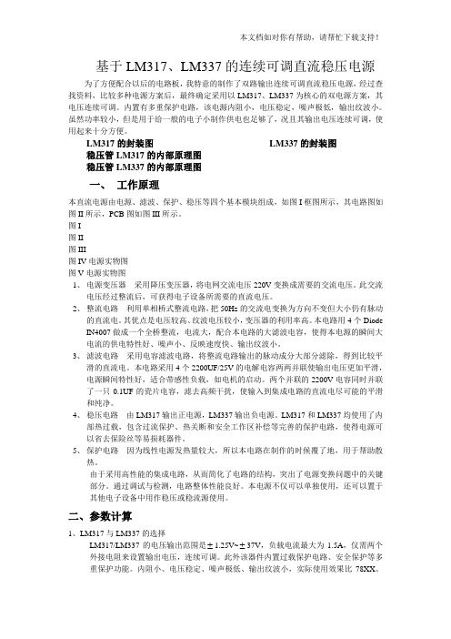
L 2 1一 M 7 7 ADJ 引 脚 排 列 如 图 1 的 所 输入 电压 V 为 4 0 ~2 V;开 关电流限制
换 器 的 内 部 开 关 管 的 开 关 电 流 可 达 示 ,各 引脚 的功能如表 1 所示 。 2 2 ( S N - . 6Q) 2 降压式 .A RD( )0 1 ;第 路 O ̄ - 转 换 器 的 内部 开 关 管 的开 关 电 流可 达 3 2 ( s N .6Q) 入电压范 围 . A RD( 1 1 o =0 ;输
1 、1 、1 、2 1 2 3 、1 、9 0 4 5
PGND AGND F Bl Vc 『
电源地 ,PGND与 AGND必须 在一个点 上连接 ( 所有的 PGND要连接在 一起 ) 模拟地 ,PGND与 AGND必须 在一个点 上连接 ( 有的 AGND要连 接在一起 ) 所 第 l 的输 出电压反馈输 入端 路 第 l 的补偿 网络连接 点 ,连接 到电压误差 放大器 的输 出端 路
图 2 出 1 V及 3 3 输 5 .V的应 用电路
电压大部分 降在 C os 上 。CBOT 的 BoT OS上 电压V。。。等于 驱动器 电压V , 。。 保证 了 N— MO E T的 V 电压值 。 SF 本文 主要介绍 电路 中一些元器件参 数 的选择 。
,
有 美参数 ( 型值 ) 典
L 77 M2 1一AD 有关参数如下:静 态 J
2 3 4 S 6 7 8 9 0 t 2
式 转 换 器 组 成 的双 输 出 、电 压可 调 的 引 脚 排 列 与功 能 I C。该器件 主要特 点 :第 1 路降 压式转
4~2 V ;输 出 电 压 可 由两 外 设 电 阻 设 0
N
~ ) D )
值 :第 1 路为 2 2 .A,第 2 为 3 2 路 .A;频 率 设定 是 电阻 R :R =4. 4 6 k Q时 ,
删 O D D 删 D 刚
一 S
一 S FS 3 0 W kH z;RF- 2 k Q时 , 0  ̄2. 6 -
应用天地
2 V, 出 l V及 3 3 的 应 用 电路 ;图 0 输 5 .V
_
3 在相 同输 入 电压 下 , 出5 是 输 V及 3 3 .V 的应用 电路 。这两 个电路的 基本参数都 相 同 ,主要差 别在设定输 出 电压到 反馈 端 的电阻分 压器的 阻值 不同 。图 2 3 、 中 的 C。。 ( 。 x值是 l 2 或 )是 自举 式升压
电 容 器 ,它 可 以提 高 驱 动 器 的 电压 ,保
证 N— MO F T有足够 的 V 电压 ,如 S E 图4 所示 。在上 电的 瞬间 , V 一 D— 从
CBo T— LX — Co T 地的 电流给 o s u x到
D 、D 1 2是 肖特 基 二极 管
C OS及 C  ̄x包 括 C UX ) g, 于 BOT oT( O TA ̄ go 由 C OS<<( o T+C ux )所 以 VI BOT C  ̄x 0TA , N的
维普资讯
应用天地
双降压式 D IC转换器 L 2 一 D CD M 7 A J 1 7
戴维德 L 77 M2 1 一ADJ 国半 公司最近 推 携式 电子 产品及膝 上计算 机等产 品。 是 出的新产 品 ,是一 种 由两个 P WM 降压
6
7 8
VG B
Vc 2 F B2
基准 电压源旁路 电容连接 端
第 2 的补偿 网络连接 点 ,连接 到电压误差 放大器 的输 出端 路 第 2路的输 出电压 反馈输 入端
l 3
l 、2 、l 4 3 5 1 6 l 、2 7 l l 8 l 9
S W2
T 2 — 2 2
一
Fw 0 k s=6 0 Ha关 闭控 觚 电源正 常工作 ,
" ¨
∞
N
N 2
洲
“ : 3
VH>1 8 .V; 电源 关 闭 ,NL .V;输 <0 7
定, 最低 电压为 12 7 .6 V;开 关频率 可设 定在 3 0~6 0 Hz 围内;内部有输 入 0 0k 范 欠压保 护及过 热保护; 4 2 引脚T S 封 S OP 装 ;工作温度 范 围 - 0 ~+1 5 4℃ 2 ℃。 该 器件 组 成 的 双 电源 主 要 应 用干 TF T—L D显示 器 、 C 手持式 电子装 置、 便 图 1L 77 A J M21- D 的引脚排列